
Hardware Installation Guide
Page 11
... a switch, and provides troubleshooting information and specifications. We assume that might arise when you are installing the switch. 78-6461-04 Catalyst 2900 Series XL Hardware Installation Guide xi Purpose The Catalyst 2900 Series... XL Hardware Installation Guide documents the hardware features of the switches, ...the physical and performance characteristics of Catalyst 2900 series XL switches. Preface Audience This guide is organized into the following chapters: Chapter ...
... a switch, and provides troubleshooting information and specifications. We assume that might arise when you are installing the switch. 78-6461-04 Catalyst 2900 Series XL Hardware Installation Guide xi Purpose The Catalyst 2900 Series... XL Hardware Installation Guide documents the hardware features of the switches, ...the physical and performance characteristics of Catalyst 2900 series XL switches. Preface Audience This guide is organized into the following chapters: Chapter ...
Hardware Installation Guide
Page 19
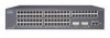
... Catalyst 2900 Series XL Hardware Installation Guide xix To access Cisco.com, go to the following website: http://www.cisco.com Technical Assistance Center The Cisco TAC website is available to all customers who need information or assistance on Cisco product capabilities, product installation, or basic product configuration. In each of an order, access technical support...
... Catalyst 2900 Series XL Hardware Installation Guide xix To access Cisco.com, go to the following website: http://www.cisco.com Technical Assistance Center The Cisco TAC website is available to all customers who need information or assistance on Cisco product capabilities, product installation, or basic product configuration. In each of an order, access technical support...

Hardware Installation Guide
Page 22
... hot swapping capability with the Cisco LRE customer premises equipment (CPE) devices • Supports up to 2048 MAC addresses on the Catalyst 2924 XL, 2924C XL, and 2912 XL switches • Supports up to 8192 MAC addresses on the Catalyst 2924M XL, Catalyst 2924M XL DC and Catalyst 2912MF XL switches Figure 1-1 shows the switch models. Catalyst 2900 Series XL Hardware...
... hot swapping capability with the Cisco LRE customer premises equipment (CPE) devices • Supports up to 2048 MAC addresses on the Catalyst 2924 XL, 2924C XL, and 2912 XL switches • Supports up to 8192 MAC addresses on the Catalyst 2924M XL, Catalyst 2924M XL DC and Catalyst 2912MF XL switches Figure 1-1 shows the switch models. Catalyst 2900 Series XL Hardware...

Hardware Installation Guide
Page 24
... Interface Options You can configure and monitor individual switches and switch clusters by using these front-panel components. Catalyst 2900 Series XL Hardware Installation Guide 1-4 78-6461-04 You can also display network topologies to gather link information and to display switch images to support desktop-switching features. The switch supports a comprehensive set of MIB extensions and four...
... Interface Options You can configure and monitor individual switches and switch clusters by using these front-panel components. Catalyst 2900 Series XL Hardware Installation Guide 1-4 78-6461-04 You can also display network topologies to gather link information and to display switch images to support desktop-switching features. The switch supports a comprehensive set of MIB extensions and four...

Hardware Installation Guide
Page 26
... Guide for speed and duplex autonegotiation, compliant with IEEE 802.3U. Pinouts for Cisco IP Phones and per-port priority override. When set for more info on the Catalyst 2900 XL switches provide protocol support for the cables are described in any compatible network device up to an AC ...power source. Cisco IP Phones-connected to the 10/100 port-must be sure that both devices support and full-duplex transmission if the ...
... Guide for speed and duplex autonegotiation, compliant with IEEE 802.3U. Pinouts for Cisco IP Phones and per-port priority override. When set for more info on the Catalyst 2900 XL switches provide protocol support for the cables are described in any compatible network device up to an AC ...power source. Cisco IP Phones-connected to the 10/100 port-must be sure that both devices support and full-duplex transmission if the ...

Hardware Installation Guide
Page 28
For more information about homologated POTS splitters, contact your Cisco sales representative. For more information about the Cisco LRE 48 POTS Splitter (PS-1M-LRE-48), refer to the Installation Notes for the Catalyst 2900 XL hot-swappable modules. Digital telephones connected to the PSTN... (ISDN), and digital private branch exchange (PBX) switch telephones that the module slots support. Note If a connection to the patch panel. Each module port is internally switched to other switch ports and is not needed, and the switch can connect directly to a telephone network is not ...
For more information about homologated POTS splitters, contact your Cisco sales representative. For more information about the Cisco LRE 48 POTS Splitter (PS-1M-LRE-48), refer to the Installation Notes for the Catalyst 2900 XL hot-swappable modules. Digital telephones connected to the PSTN... (ISDN), and digital private branch exchange (PBX) switch telephones that the module slots support. Note If a connection to the patch panel. Each module port is internally switched to other switch ports and is not needed, and the switch can connect directly to a telephone network is not ...

Hardware Installation Guide
Page 29
... Series XL Hardware Installation Guide 1-9 These modules automatically configure themselves when you insert them in a 2924M XL or Catalyst 2912MF XL switch (both supporting 8192 MAC addresses), the module fails POST. Figure 1-5, Figure 1-6, and Figure 1-7 show the location of these modules in ... Gigabit Interface Converter (GBIC) devices. Note Modules WS-X2914-XL and WS-X2922-XL support 2048 MAC addresses. You can use to the Release Notes for Catalyst 2900 series XL switches. For a complete list and the minimum software release required, refer to select a port mode. Changing ...
... Series XL Hardware Installation Guide 1-9 These modules automatically configure themselves when you insert them in a 2924M XL or Catalyst 2912MF XL switch (both supporting 8192 MAC addresses), the module fails POST. Figure 1-5, Figure 1-6, and Figure 1-7 show the location of these modules in ... Gigabit Interface Converter (GBIC) devices. Note Modules WS-X2914-XL and WS-X2922-XL support 2048 MAC addresses. You can use to the Release Notes for Catalyst 2900 series XL switches. For a complete list and the minimum software release required, refer to select a port mode. Changing ...

Hardware Installation Guide
Page 38
...support Cisco IOS Release 12.0(5.x)WC3. 3. Figure 1-9 Bandwidth Utilization 47293 SYSTEM 10BaseT/100BaseTx RPS 1x 2x 3x 4x 5x 6x 7x 8x MODE 9x 10x 11x 12x 6.25 -12.4%+ 12.5 -24%+ 25 - 49%+ 50%+ Catalyst 2900 SERIES XL 1-18 Catalyst 2900 Series XL Hardware Installation Guide 78-6461-04 The Catalyst 2900 LRE XL switches... do not support the Cisco 585 LRE CPE devices. 2. Figure 1-9 shows bandwidth utilization percentages...
...support Cisco IOS Release 12.0(5.x)WC3. 3. Figure 1-9 Bandwidth Utilization 47293 SYSTEM 10BaseT/100BaseTx RPS 1x 2x 3x 4x 5x 6x 7x 8x MODE 9x 10x 11x 12x 6.25 -12.4%+ 12.5 -24%+ 25 - 49%+ 50%+ Catalyst 2900 SERIES XL 1-18 Catalyst 2900 Series XL Hardware Installation Guide 78-6461-04 The Catalyst 2900 LRE XL switches... do not support the Cisco 585 LRE CPE devices. 2. Figure 1-9 shows bandwidth utilization percentages...
Hardware Installation Guide
Page 41
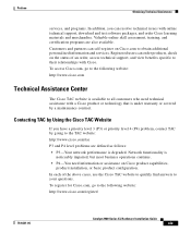
... Power Source" section on page 2-29. 78-6461-04 Catalyst 2900 Series XL Hardware Installation Guide 1-21 Note The Cisco RPS does not support the Catalyst 2924M XL DC switch. DC Power Connector The Catalyst 2924M XL DC switch has an internal DC-power converter. Internal Power Supply Connector The...cord to connect the AC power connector to the switch either through the internal power supply or through the Cisco RPS. Power Connectors You can provide power to an AC power outlet. Chapter 1 Product Overview Figure 1-13 Catalyst 2924M XL Rear Panel Power Connectors 74070 CONSOLE ...
... Power Source" section on page 2-29. 78-6461-04 Catalyst 2900 Series XL Hardware Installation Guide 1-21 Note The Cisco RPS does not support the Catalyst 2924M XL DC switch. DC Power Connector The Catalyst 2924M XL DC switch has an internal DC-power converter. Internal Power Supply Connector The...cord to connect the AC power connector to the switch either through the internal power supply or through the Cisco RPS. Power Connectors You can provide power to an AC power outlet. Chapter 1 Product Overview Figure 1-13 Catalyst 2924M XL Rear Panel Power Connectors 74070 CONSOLE ...

Hardware Installation Guide
Page 42
... Cisco RPS models support specific Catalyst 2900 XL switches: • Cisco RPS 600 (model PWR600-AC-RPS)-supports the Catalyst 2912 XL, 2924C XL, 2924 XL, 2924MF XL, and 2924M XL switches. • Cisco RPS 300 (model PWR300-AC-RPS-N1)-supports the Catalyst 2912 LRE XL and 2924 LRE XL switches Note The Cisco RPS does not support the Catalyst 2924M XL DC switch. The switches...
... Cisco RPS models support specific Catalyst 2900 XL switches: • Cisco RPS 600 (model PWR600-AC-RPS)-supports the Catalyst 2912 XL, 2924C XL, 2924 XL, 2924MF XL, and 2924M XL switches. • Cisco RPS 300 (model PWR300-AC-RPS-N1)-supports the Catalyst 2912 LRE XL and 2924 LRE XL switches Note The Cisco RPS does not support the Catalyst 2924M XL DC switch. The switches...

Hardware Installation Guide
Page 43
...see the "Connecting to a terminal. Note The RPS can only power one switch at a time. If more information on the Cisco RPS 300, refer to one switch fails at the same time, any subsequent switch is not supported by using the supplied rollover cable and DB-9 adapter. You need to provide...Series XL Hardware Installation Guide 1-23 Chapter 1 Product Overview Power Connectors RPS Connector on the Catalyst 2912 LRE and 2924 LRE XL Switches The RPS is a 300W redundant power system that adapter from Cisco. For more than one failed device at a time. It automatically senses when the power ...
...see the "Connecting to a terminal. Note The RPS can only power one switch at a time. If more information on the Cisco RPS 300, refer to one switch fails at the same time, any subsequent switch is not supported by using the supplied rollover cable and DB-9 adapter. You need to provide...Series XL Hardware Installation Guide 1-23 Chapter 1 Product Overview Power Connectors RPS Connector on the Catalyst 2912 LRE and 2924 LRE XL Switches The RPS is a 300W redundant power system that adapter from Cisco. For more than one failed device at a time. It automatically senses when the power ...

Hardware Installation Guide
Page 51
...4921 feet (1500 meters). • Cabling is away from the shipping container, and check each item for damage. Your Catalyst 2900 XL switch is within reach of the expansion modules, refer to the shipping container and save them. Rear-panel power connector is within... is installed in a closed or multirack assembly, the temperature around the switch and through the vents is sufficient for support. Front-panel indicators can be greater than normal room temperature. Note If the switch is missing or damaged, contact your Cisco representative or reseller for unrestricted cabling. -
...4921 feet (1500 meters). • Cabling is away from the shipping container, and check each item for damage. Your Catalyst 2900 XL switch is within reach of the expansion modules, refer to the shipping container and save them. Rear-panel power connector is within... is installed in a closed or multirack assembly, the temperature around the switch and through the vents is sufficient for support. Front-panel indicators can be greater than normal room temperature. Note If the switch is missing or damaged, contact your Cisco representative or reseller for unrestricted cabling. -

Hardware Installation Guide
Page 52
...of the mounting brackets Note The cable guide does not attach to the Catalyst 2912 LRE XL and 2924 LRE XL switches. • One RJ-45-to-DB-9 adapter • Cisco Information Packet, containing warranty, safety, and support information Note In addition to a rack - Four number-8 Phillips truss...-head screws for attaching the brackets to the switch (19-inch rack mount) - Four ...
...of the mounting brackets Note The cable guide does not attach to the Catalyst 2912 LRE XL and 2924 LRE XL switches. • One RJ-45-to-DB-9 adapter • Cisco Information Packet, containing warranty, safety, and support information Note In addition to a rack - Four number-8 Phillips truss...-head screws for attaching the brackets to the switch (19-inch rack mount) - Four ...
Hardware Installation Guide
Page 60
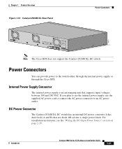
... or 24-inch rack. or 24-inch rack, the switch sags towards the rear of the switch. The mounting brackets shipped with a Catalyst 2900 LRE XL switch cannot support the switch in a 23- Installing the Switch in a Rack Chapter 2 Installation Attaching the Brackets to the switch. To attach the brackets to a Catalyst 2912 LRE XL or 2924 LRE XL...
... or 24-inch rack. or 24-inch rack, the switch sags towards the rear of the switch. The mounting brackets shipped with a Catalyst 2900 LRE XL switch cannot support the switch in a 23- Installing the Switch in a Rack Chapter 2 Installation Attaching the Brackets to the switch. To attach the brackets to a Catalyst 2912 LRE XL or 2924 LRE XL...
Hardware Installation Guide
Page 66
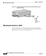
Installing the Switch on a Wall Chapter 2 Installation Figure 2-14 Attaching Brackets for Parallel and Vertical Wall-Mounting for Modular Switches DC INPUT 21.000A-/11R2.0A0AT/2IN050G0--26400HVZ~ 47304 Phillips truss-head screws Mounting the Switch to a Wall For best support of the switch and cables, make sure the switch is attached securely to a wall stud or to a firmly attached plywood mounting backboard, as shown in Figure 2-15, Figure 2-16, and Figure 2-28. 2-22 Catalyst 2900 Series XL Hardware Installation Guide 78-6461-04
Installing the Switch on a Wall Chapter 2 Installation Figure 2-14 Attaching Brackets for Parallel and Vertical Wall-Mounting for Modular Switches DC INPUT 21.000A-/11R2.0A0AT/2IN050G0--26400HVZ~ 47304 Phillips truss-head screws Mounting the Switch to a Wall For best support of the switch and cables, make sure the switch is attached securely to a wall stud or to a firmly attached plywood mounting backboard, as shown in Figure 2-15, Figure 2-16, and Figure 2-28. 2-22 Catalyst 2900 Series XL Hardware Installation Guide 78-6461-04

Hardware Installation Guide
Page 79
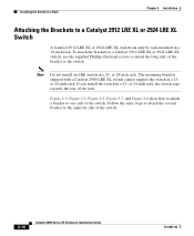
Connecting devices that do not support autonegotiation, you can reduce performance or result... steps to connect to 10BASE-T and 100BASE-TX devices: Step 1 When connecting to workstations, servers, routers, and Cisco IP Phones, connect a straight-through Category 5 cable to a 10/100 Port 74080 CONSOLE BERFEOFREERPOCTOWONEMNRAENCUTAINL G DC INPUT ... on page B-4. 78-6461-04 Catalyst 2900 Series XL Hardware Installation Guide 2-35 Terminal block plug Tie wrap Connecting to a 10/100 Port The switch 10/100 ports configure themselves to switches or repeaters, use a crossover Category...
Connecting devices that do not support autonegotiation, you can reduce performance or result... steps to connect to 10BASE-T and 100BASE-TX devices: Step 1 When connecting to workstations, servers, routers, and Cisco IP Phones, connect a straight-through Category 5 cable to a 10/100 Port 74080 CONSOLE BERFEOFREERPOCTOWONEMNRAENCUTAINL G DC INPUT ... on page B-4. 78-6461-04 Catalyst 2900 Series XL Hardware Installation Guide 2-35 Terminal block plug Tie wrap Connecting to a 10/100 Port The switch 10/100 ports configure themselves to switches or repeaters, use a crossover Category...
Hardware Installation Guide
Page 81
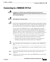
..., such as shown in Figure 2-29. 78-6461-04 Catalyst 2900 Series XL Hardware Installation Guide 2-37 The fiber-optic distances between the switch and the attached device follow these ports to other switches. Note Speed and duplex-mode autonegotiation is not supported on the switch, as servers, routers, and other 100BASE-FX devices. Chapter...
..., such as shown in Figure 2-29. 78-6461-04 Catalyst 2900 Series XL Hardware Installation Guide 2-37 The fiber-optic distances between the switch and the attached device follow these ports to other switches. Note Speed and duplex-mode autonegotiation is not supported on the switch, as servers, routers, and other 100BASE-FX devices. Chapter...

Hardware Installation Guide
Page 86
The PC or terminal must support VT100 terminal emulation. Follow these switch console port default characteristics: • 9600 baud • 8 data bits • 1 stop bit • No parity After you have accessed the switch, you want to connect the switch console port to a terminal. Configure... you can order a kit (part number ACS-DSBUASYN=) containing that adapter from Cisco. See the Catalyst 2900 Series XL and Catalyst 3500 Series XL Software Configuration Guide for instructions. 2-42 Catalyst 2900 Series XL Hardware Installation Guide 78-6461-04 You need to provide a...
The PC or terminal must support VT100 terminal emulation. Follow these switch console port default characteristics: • 9600 baud • 8 data bits • 1 stop bit • No parity After you have accessed the switch, you want to connect the switch console port to a terminal. Configure... you can order a kit (part number ACS-DSBUASYN=) containing that adapter from Cisco. See the Catalyst 2900 Series XL and Catalyst 3500 Series XL Software Configuration Guide for instructions. 2-42 Catalyst 2900 Series XL Hardware Installation Guide 78-6461-04 You need to provide a...
Hardware Installation Guide
Page 90
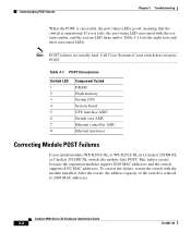
...the restart, the address capacity of the switch is operational. Call Cisco Systems if your switch does not pass POST. Table 3-1 POST Descriptions Switch LED 1 2 3 4 5 6 7 8 Component Tested DRAM Flash memory Switch CPU System board CPU interface ASIC Switch core ASIC Ethernet controller ASIC Ethernet interfaces...WS-X2922-XL in a Catalyst 2924M XL or Catalyst 2912MF XL switch, the module fails POST. This failure occurs because the expansion modules support 2048 MAC addresses and the switch supports 8192 MAC addresses. To correct the failure, restart the switch with the test turns amber,...
...the restart, the address capacity of the switch is operational. Call Cisco Systems if your switch does not pass POST. Table 3-1 POST Descriptions Switch LED 1 2 3 4 5 6 7 8 Component Tested DRAM Flash memory Switch CPU System board CPU interface ASIC Switch core ASIC Ethernet controller ASIC Ethernet interfaces...WS-X2922-XL in a Catalyst 2924M XL or Catalyst 2912MF XL switch, the module fails POST. This failure occurs because the expansion modules support 2048 MAC addresses and the switch supports 8192 MAC addresses. To correct the failure, restart the switch with the test turns amber,...
Hardware Installation Guide
Page 95
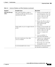
...Cisco sales representative for installation optimization. 78-6461-04 Catalyst 2900 Series XL Hardware Installation Guide 3-7 Local nonstandard noise source. Chapter 3 Troubleshooting Diagnosing Problems Table 3-2 Common Problems and Their Solutions (continued) Symptom LRE status LED stays amber. Trunk quality too poor to support... other services. • Restrict the use of stubs or bridge taps by the switch. • Change to the Catalyst 2900 Series XL and Catalyst 3500 Series XL Software Configuration Guide. • Assess possibility of spectrally incompatible services....
...Cisco sales representative for installation optimization. 78-6461-04 Catalyst 2900 Series XL Hardware Installation Guide 3-7 Local nonstandard noise source. Chapter 3 Troubleshooting Diagnosing Problems Table 3-2 Common Problems and Their Solutions (continued) Symptom LRE status LED stays amber. Trunk quality too poor to support... other services. • Restrict the use of stubs or bridge taps by the switch. • Change to the Catalyst 2900 Series XL and Catalyst 3500 Series XL Software Configuration Guide. • Assess possibility of spectrally incompatible services....


