
Hardware Installation Guide
Page 2
...specifications in part 15 of the UNIX operating system. The Cisco implementation of TCP header compression is an adaptation of a program developed by Cisco Systems, Inc. and Aironet, ASIST, BPX, Catalyst, CCDA, CCDP, CCIE, CCNA, CCNP, Cisco, the Cisco Certified Internetwork Expert logo, Cisco IOS, the Cisco IOS logo, Cisco Press, Cisco Systems, Cisco Systems Capital, the Cisco...in this equipment in accordance with radio and television reception. Operation of Cisco Systems, Inc.; If it off. These specifications are on a different circuit from the television or radio. •...
...specifications in part 15 of the UNIX operating system. The Cisco implementation of TCP header compression is an adaptation of a program developed by Cisco Systems, Inc. and Aironet, ASIST, BPX, Catalyst, CCDA, CCDP, CCIE, CCNA, CCNP, Cisco, the Cisco Certified Internetwork Expert logo, Cisco IOS, the Cisco IOS logo, Cisco Press, Cisco Systems, Cisco Systems Capital, the Cisco...in this equipment in accordance with radio and television reception. Operation of Cisco Systems, Inc.; If it off. These specifications are on a different circuit from the television or radio. •...

Hardware Installation Guide
Page 7
... 2-19 Installing the Switch on a Wall 2-20 Attaching the Brackets to the Switch 2-21 Mounting the Switch to a Wall 2-22 Powering On the Switch and Running POST 2-24 Connecting to DC Power 2-25 Preparing for Installation 2-25 Grounding the Switch 2-26 Wiring the... Go Next 2-43 Troubleshooting 3-1 Understanding POST Results 3-1 Correcting Module POST Failures 3-2 Diagnosing Problems 3-3 Technical Specifications A-1 Connectors and Cable Specifications B-1 Connector Specifications B-1 10/100 Ports B-1 100BASE-FX Ports B-2 Contents 78-6461-04 Catalyst 2900 Series XL Hardware Installation Guide vii
... 2-19 Installing the Switch on a Wall 2-20 Attaching the Brackets to the Switch 2-21 Mounting the Switch to a Wall 2-22 Powering On the Switch and Running POST 2-24 Connecting to DC Power 2-25 Preparing for Installation 2-25 Grounding the Switch 2-26 Wiring the... Go Next 2-43 Troubleshooting 3-1 Understanding POST Results 3-1 Correcting Module POST Failures 3-2 Diagnosing Problems 3-3 Technical Specifications A-1 Connectors and Cable Specifications B-1 Connector Specifications B-1 10/100 Ports B-1 100BASE-FX Ports B-2 Contents 78-6461-04 Catalyst 2900 Series XL Hardware Installation Guide vii

Hardware Installation Guide
Page 8
... Ports B-3 Console Port B-3 Cable and Adapter Specifications B-4 Crossover and Straight-Through Cable Pinouts B-4 RJ-21 Cable Pinouts B-5 Console Port B-5 Identifying a Rollover Cable B-6 Connecting to a PC B-6 Connecting to a Terminal B-7 Translated Safety Warnings C-1 Attaching the Cisco RPS (model PWR600-AC-RPS) C-1 Attaching the Cisco RPS (model PWR300-AC-RPS-N1) C-2 Qualified... C-14 Supply Circuit Warning C-15 Voltage Warning C-16 Power Supply Warning C-17 Lightning Activity Warning C-19 Product Disposal Warning C-21 Catalyst 2900 Series XL Hardware Installation Guide viii 78-6461-04
... Ports B-3 Console Port B-3 Cable and Adapter Specifications B-4 Crossover and Straight-Through Cable Pinouts B-4 RJ-21 Cable Pinouts B-5 Console Port B-5 Identifying a Rollover Cable B-6 Connecting to a PC B-6 Connecting to a Terminal B-7 Translated Safety Warnings C-1 Attaching the Cisco RPS (model PWR600-AC-RPS) C-1 Attaching the Cisco RPS (model PWR300-AC-RPS-N1) C-2 Qualified... C-14 Supply Circuit Warning C-15 Voltage Warning C-16 Power Supply Warning C-17 Lightning Activity Warning C-19 Product Disposal Warning C-21 Catalyst 2900 Series XL Hardware Installation Guide viii 78-6461-04

Hardware Installation Guide
Page 11
...Catalyst 2900 Series XL Hardware Installation Guide documents the hardware features of the switches, explains how to identify and resolve some of the problems that you are familiar with the concepts and terminology of Ethernet and local area networking. Chapter 3, "Troubleshooting," describes how to install a switch, and provides troubleshooting information and specifications.... Preface Audience This guide is organized into the following chapters: Chapter 1, "Product Overview," summarizes the switch features and...
...Catalyst 2900 Series XL Hardware Installation Guide documents the hardware features of the switches, explains how to identify and resolve some of the problems that you are familiar with the concepts and terminology of Ethernet and local area networking. Chapter 3, "Troubleshooting," describes how to install a switch, and provides troubleshooting information and specifications.... Preface Audience This guide is organized into the following chapters: Chapter 1, "Product Overview," summarizes the switch features and...

Hardware Installation Guide
Page 12
...• Commands and keywords are in boldface. • Arguments for the switches and the regulatory agency approvals. Notes contain helpful suggestions or references to the switch. Appendix B, "Connectors and Cable Specifications," describes the connectors, cables, and adapters that could result in equipment damage... enter is in boldface screen font. • Nonprinting characters, such as passwords or tabs, are in this guide. Catalyst 2900 Series XL Hardware Installation Guide xii 78-6461-04 Conventions This guide uses the following conventions to convey instructions and ...
...• Commands and keywords are in boldface. • Arguments for the switches and the regulatory agency approvals. Notes contain helpful suggestions or references to the switch. Appendix B, "Connectors and Cable Specifications," describes the connectors, cables, and adapters that could result in equipment damage... enter is in boldface screen font. • Nonprinting characters, such as passwords or tabs, are in this guide. Catalyst 2900 Series XL Hardware Installation Guide xii 78-6461-04 Conventions This guide uses the following conventions to convey instructions and ...

Hardware Installation Guide
Page 18
... find information about Cisco and our networking solutions, xviii Catalyst 2900 Series XL Hardware Installation Guide 78-6461-04 If you are using the product-specific CD and you are connected to the following address: Cisco Systems, Inc. You can mail your comments to display the survey. Obtaining Technical Assistance Cisco provides Cisco.com as a starting...
... find information about Cisco and our networking solutions, xviii Catalyst 2900 Series XL Hardware Installation Guide 78-6461-04 If you are using the product-specific CD and you are connected to the following address: Cisco Systems, Inc. You can mail your comments to display the survey. Obtaining Technical Assistance Cisco provides Cisco.com as a starting...
Hardware Installation Guide
Page 19
... available to all customers who need information or assistance on Cisco.com to the following website: http://www.cisco.com/register/ 78-6461-04 Catalyst 2900 Series XL Hardware Installation Guide xix Preface Obtaining Technical ...Cisco product or technology that is noticeably impaired, but most business operations continue. • P4-You need technical assistance with Cisco. Customers and partners can self-register on Cisco product capabilities, product installation, or basic product configuration. In each of an order, access technical support, and view benefits specific...
... available to all customers who need information or assistance on Cisco.com to the following website: http://www.cisco.com/register/ 78-6461-04 Catalyst 2900 Series XL Hardware Installation Guide xix Preface Obtaining Technical ...Cisco product or technology that is noticeably impaired, but most business operations continue. • P4-You need technical assistance with Cisco. Customers and partners can self-register on Cisco product capabilities, product installation, or basic product configuration. In each of an order, access technical support, and view benefits specific...

Hardware Installation Guide
Page 24
...graphical user interface that can fully configure and monitor a standalone switch, a specific cluster member, or an entire switch cluster. You can manage the switch from anywhere in your management station directly to support desktop-switching features. You can also display network topologies to gather link ...protocol (SNMP)-SNMP provides a means to the Catalyst 2900 Series XL and Catalyst 3500 Series XL Software Configuration Guide. For more information about CMS, the CLI, and SNMP refer to monitor and control the switch and switch cluster members. You can access the CLI either...
...graphical user interface that can fully configure and monitor a standalone switch, a specific cluster member, or an entire switch cluster. You can manage the switch from anywhere in your management station directly to support desktop-switching features. You can also display network topologies to gather link ...protocol (SNMP)-SNMP provides a means to the Catalyst 2900 Series XL and Catalyst 3500 Series XL Software Configuration Guide. For more information about CMS, the CLI, and SNMP refer to monitor and control the switch and switch cluster members. You can access the CLI either...

Hardware Installation Guide
Page 26
.... These ports also can be connected to an AC power source. The 10/100 ports on the Catalyst 3524-PWR XL switch, refer to workstations, servers, routers, and Cisco IP Phones, be explicitly set for autonegotiation, the port senses the speed and duplex settings of half duplex...port-must be set for the cables are described in any compatible network device up to operate in Appendix B, "Connectors and Cable Specifications." Cisco IP Phones-connected to switches or hubs, use Category 3 and 4 cables. Pinouts for speed and duplex autonegotiation, compliant with IEEE 802.3U. When set...
.... These ports also can be connected to an AC power source. The 10/100 ports on the Catalyst 3524-PWR XL switch, refer to workstations, servers, routers, and Cisco IP Phones, be explicitly set for autonegotiation, the port senses the speed and duplex settings of half duplex...port-must be set for the cables are described in any compatible network device up to operate in Appendix B, "Connectors and Cable Specifications." Cisco IP Phones-connected to switches or hubs, use Category 3 and 4 cables. Pinouts for speed and duplex autonegotiation, compliant with IEEE 802.3U. When set...

Hardware Installation Guide
Page 33
... Status RPS is not installed. Refer to the appropriate switch documentation for redundant power system (RPS) descriptions specific for the switch. Figure 1-8 RPS LED on the Catalyst 2912 LRE XL and 2924 LRE XL Switches Color Off Solid green Blinking green RPS Status RPS is... off or is off or not properly connected. RPS is not a recommended configuration. All other Catalyst 2900 XL and Catalyst 3500 XL switches use the Cisco...
... Status RPS is not installed. Refer to the appropriate switch documentation for redundant power system (RPS) descriptions specific for the switch. Figure 1-8 RPS LED on the Catalyst 2912 LRE XL and 2924 LRE XL Switches Color Off Solid green Blinking green RPS Status RPS is... off or is off or not properly connected. RPS is not a recommended configuration. All other Catalyst 2900 XL and Catalyst 3500 XL switches use the Cisco...

Hardware Installation Guide
Page 42
... described in this range, the switch might not operate properly or might be damaged. If the supply voltage is not. Cisco RPS Connector Specific Cisco RPS models support specific Catalyst 2900 XL switches: • Cisco RPS 600 (model PWR600-AC-RPS)-supports the Catalyst 2912 XL, 2924C XL, 2924... XL, 2924MF XL, and 2924M XL switches. • Cisco RPS 300 (model PWR300-AC-RPS-...
... described in this range, the switch might not operate properly or might be damaged. If the supply voltage is not. Cisco RPS Connector Specific Cisco RPS models support specific Catalyst 2900 XL switches: • Cisco RPS 600 (model PWR600-AC-RPS)-supports the Catalyst 2912 XL, 2924C XL, 2924... XL, 2924MF XL, and 2924M XL switches. • Cisco RPS 300 (model PWR300-AC-RPS-...

Hardware Installation Guide
Page 51
... lighting fixtures. • For specifications of an AC power receptacle. • Operating environment is within the ranges listed in the Related Publications, page xv. • Clearance to Find the Catalyst 2900 XL and Catalyst 3500 XL Documentation flyer • Cisco Documentation CD-ROM • AC...1500 meters). • Cabling is away from the shipping container, and check each item for support. Your Catalyst 2900 XL switch is unrestricted. • Temperature around the switch and through the vents is shipped with these items: • Where to front and rear panels meet these...
... lighting fixtures. • For specifications of an AC power receptacle. • Operating environment is within the ranges listed in the Related Publications, page xv. • Clearance to Find the Catalyst 2900 XL and Catalyst 3500 XL Documentation flyer • Cisco Documentation CD-ROM • AC...1500 meters). • Cabling is away from the shipping container, and check each item for support. Your Catalyst 2900 XL switch is unrestricted. • Temperature around the switch and through the vents is shipped with these items: • Where to front and rear panels meet these...

Hardware Installation Guide
Page 79
...support autonegotiation, you can explicitly set can reduce performance or result in the "Cable and Adapter Specifications" section on the front panel (Figure 2-28). Pinouts for configuring the 10/100 Ethernet ports... the connection. Terminal block plug Tie wrap Connecting to a 10/100 Port The switch 10/100 ports configure themselves to operate at the speed of these steps to connect... to workstations, servers, routers, and Cisco IP Phones, connect a straight-through Category 5 cable to an RJ-45 connector on page B-4. 78-6461-04 Catalyst 2900 Series XL Hardware Installation Guide 2-...
...support autonegotiation, you can explicitly set can reduce performance or result in the "Cable and Adapter Specifications" section on the front panel (Figure 2-28). Pinouts for configuring the 10/100 Ethernet ports... the connection. Terminal block plug Tie wrap Connecting to a 10/100 Port The switch 10/100 ports configure themselves to operate at the speed of these steps to connect... to workstations, servers, routers, and Cisco IP Phones, connect a straight-through Category 5 cable to an RJ-45 connector on page B-4. 78-6461-04 Catalyst 2900 Series XL Hardware Installation Guide 2-...

Hardware Installation Guide
Page 86
...part number ACS-DSBUASYN=) containing that adapter from Cisco. You need to provide a RJ-45-to the switch: Step 1 Step 2 Configure your PC or...and connecting to modules in the Catalyst 2924M XL and 2912MF XL module slots, refer to communicate with the switch through hardware flow control. The ...switch, you want to connect the switch console port to the switch console port. Connecting to the Console Port Use the supplied rollover cable and DB-9 adapter to connect a PC to a terminal. For console port and adapter pinout information, see the "Cable and Adapter Specifications...
...part number ACS-DSBUASYN=) containing that adapter from Cisco. You need to provide a RJ-45-to the switch: Step 1 Step 2 Configure your PC or...and connecting to modules in the Catalyst 2924M XL and 2912MF XL module slots, refer to communicate with the switch through hardware flow control. The ...switch, you want to connect the switch console port to the switch console port. Connecting to the Console Port Use the supplied rollover cable and DB-9 adapter to connect a PC to a terminal. For console port and adapter pinout information, see the "Cable and Adapter Specifications...

Hardware Installation Guide
Page 99
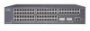
A A P P E N D I X Technical Specifications Table A-1, Table A-2, Table A-3, and Table A-5 list the technical specifications for EMI and safety. 78-6461-04 Catalyst 2900 Series XL Hardware Installation Guide A-1 Table A-6 lists the agency approvals for the Catalyst 2900 series switches. For switches that support modules (Catalyst 2912MF XL and 2924M XL), also refer to the Catalyst 2900 Series XL Modules Installation Guide and the Catalyst 2900 Series XL ATM Modules Installation Guide for additional specifications.
A A P P E N D I X Technical Specifications Table A-1, Table A-2, Table A-3, and Table A-5 list the technical specifications for EMI and safety. 78-6461-04 Catalyst 2900 Series XL Hardware Installation Guide A-1 Table A-6 lists the agency approvals for the Catalyst 2900 series switches. For switches that support modules (Catalyst 2912MF XL and 2924M XL), also refer to the Catalyst 2900 Series XL Modules Installation Guide and the Catalyst 2900 Series XL ATM Modules Installation Guide for additional specifications.
Hardware Installation Guide
Page 100
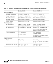
Appendix A Technical Specifications Table A-1 Technical Specifications for the Catalyst 2912 XL and Catalyst 2912MF XL Switches Environmental Ranges Operating temperature Storage temperature Operating humidity Operating altitude Storage altitude Power Requirements AC input voltage DC input voltages Catalyst 2912 XL 32 to 113°F (0 to 45°C) -4 ...(maximum) 239 Btus per hour 7 lb (3.2 kg) Dimensions (H x W x D) 1.73 x 17.5 x 9.79 in. (4.4 x 44.5 x 24.8 cm) Catalyst 2912MF XL 32 to 113°F (0 to 45°C) -4 to 149°F (-10 to 65°C) 10 to 85% (noncondensing) Up to 10,000 ft...
Appendix A Technical Specifications Table A-1 Technical Specifications for the Catalyst 2912 XL and Catalyst 2912MF XL Switches Environmental Ranges Operating temperature Storage temperature Operating humidity Operating altitude Storage altitude Power Requirements AC input voltage DC input voltages Catalyst 2912 XL 32 to 113°F (0 to 45°C) -4 ...(maximum) 239 Btus per hour 7 lb (3.2 kg) Dimensions (H x W x D) 1.73 x 17.5 x 9.79 in. (4.4 x 44.5 x 24.8 cm) Catalyst 2912MF XL 32 to 113°F (0 to 45°C) -4 to 149°F (-10 to 65°C) 10 to 85% (noncondensing) Up to 10,000 ft...

Hardware Installation Guide
Page 101
nm = nanometers 2. Transmit - 1. wavelength Optical sensibility of the - dBm = decibel milliwatt Catalyst 2924C XL 32 to 113°F (0 to 45°C) -4 to 149°F (-10 to 65°C) 10 to 85% (noncondensing)...200 to 240 VAC (autoranging) 50 to -14 dBm 78-6461-04 Catalyst 2900 Series XL Hardware Installation Guide A-3 receiver Optical power transmitter - Appendix A Technical Specifications Table A-2 Technical Specifications for the Catalyst 2924 XL and Catalyst 2924C XL Switches Catalyst 2924 XL Environmental Operating Ranges Operating temperature 32 to 113°F (0 to ...
nm = nanometers 2. Transmit - 1. wavelength Optical sensibility of the - dBm = decibel milliwatt Catalyst 2924C XL 32 to 113°F (0 to 45°C) -4 to 149°F (-10 to 65°C) 10 to 85% (noncondensing)...200 to 240 VAC (autoranging) 50 to -14 dBm 78-6461-04 Catalyst 2900 Series XL Hardware Installation Guide A-3 receiver Optical power transmitter - Appendix A Technical Specifications Table A-2 Technical Specifications for the Catalyst 2924 XL and Catalyst 2924C XL Switches Catalyst 2924 XL Environmental Operating Ranges Operating temperature 32 to 113°F (0 to ...
Hardware Installation Guide
Page 102
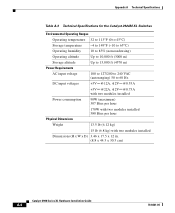
Appendix A Technical Specifications Table A-3 Technical Specifications for the Catalyst 2924M XL Switches Environmental Operating Ranges Operating temperature 32 to 113°F (0 to 45°C) Storage temperature -4 to 149°F (-10 to 65°C) Operating humidity 10 to ... Btus per hour Physical Dimensions Weight 13.5 lb (6.12 kg) 15 lb (6.8 kg) with two modules installed Dimensions (H x W x D) 3.46 x 17.5 x 12 in. (8.8 x 44.5 x 30.5 cm) Catalyst 2900 Series XL Hardware Installation Guide A-4 78-6461-04
Appendix A Technical Specifications Table A-3 Technical Specifications for the Catalyst 2924M XL Switches Environmental Operating Ranges Operating temperature 32 to 113°F (0 to 45°C) Storage temperature -4 to 149°F (-10 to 65°C) Operating humidity 10 to ... Btus per hour Physical Dimensions Weight 13.5 lb (6.12 kg) 15 lb (6.8 kg) with two modules installed Dimensions (H x W x D) 3.46 x 17.5 x 12 in. (8.8 x 44.5 x 30.5 cm) Catalyst 2900 Series XL Hardware Installation Guide A-4 78-6461-04
Hardware Installation Guide
Page 103
... (6.8 kg) with two modules installed 3.46 x 17.5 x 12 in. (8.8 x 44.5 x 30.5 cm) Table A-5 Technical Specifications for power connection Branch circuit protection Physical Dimensions Weight Dimensions (H x W x D) 1. Appendix A Technical Specifications 78-6461-04 Table A-4 Technical Specifications for Catalyst 2924M XL DC Switches Environmental Ranges Operating temperature Storage temperature Operating humidity Operating altitude Storage altitude Power Requirements Power...
... (6.8 kg) with two modules installed 3.46 x 17.5 x 12 in. (8.8 x 44.5 x 30.5 cm) Table A-5 Technical Specifications for power connection Branch circuit protection Physical Dimensions Weight Dimensions (H x W x D) 1. Appendix A Technical Specifications 78-6461-04 Table A-4 Technical Specifications for Catalyst 2924M XL DC Switches Environmental Ranges Operating temperature Storage temperature Operating humidity Operating altitude Storage altitude Power Requirements Power...
Hardware Installation Guide
Page 104
... A Technical Specifications Table A-5 Technical Specifications for the Catalyst 2912 LRE XL and 2924 LRE XL Switches (continued) AC input voltage 100 to 127/200 to 240 VAC (autoranging) 50 to 60 Hz DC input voltages +12V @12A Power consumption 70W Physical Dimensions Weight • Catalyst 2912 LRE XL 8.75 lb (4 kg) • Catalyst 2924 LRE XL..., TS001 CE EMI FCC Part 15 Class A EN 55022 Class A (CISPR 22 Class A) VCCI Class A AS/NZS 3548 Class A BCIQ CE Table A-7 Agency Approvals (Catalyst 2924M XL DC Switch) Safety NOM 019 BSMI EMC EN 50082-1 Class A BSMI NEBS GR-1089 GR-63...
... A Technical Specifications Table A-5 Technical Specifications for the Catalyst 2912 LRE XL and 2924 LRE XL Switches (continued) AC input voltage 100 to 127/200 to 240 VAC (autoranging) 50 to 60 Hz DC input voltages +12V @12A Power consumption 70W Physical Dimensions Weight • Catalyst 2912 LRE XL 8.75 lb (4 kg) • Catalyst 2924 LRE XL..., TS001 CE EMI FCC Part 15 Class A EN 55022 Class A (CISPR 22 Class A) VCCI Class A AS/NZS 3548 Class A BCIQ CE Table A-7 Agency Approvals (Catalyst 2924M XL DC Switch) Safety NOM 019 BSMI EMC EN 50082-1 Class A BSMI NEBS GR-1089 GR-63...