Hardware Installation Guide
Page 1
Catalyst 2900 Series XL Hardware Installation Guide April 2002 Corporate Headquarters Cisco Systems, Inc. 170 West Tasman Drive San Jose, CA 95134-1706 USA http://www.cisco.com Tel: 408 526-4000 800 553-NETS (6387) Fax: 408 526-4100 Customer Order Number: DOC-786461= Text Part Number: 78-6461-04
Catalyst 2900 Series XL Hardware Installation Guide April 2002 Corporate Headquarters Cisco Systems, Inc. 170 West Tasman Drive San Jose, CA 95134-1706 USA http://www.cisco.com Tel: 408 526-4000 800 553-NETS (6387) Fax: 408 526-4100 Customer Order Number: DOC-786461= Text Part Number: 78-6461-04

Hardware Installation Guide
Page 2
... its peripheral devices. The following information is an adaptation of a program developed by Cisco Systems, Inc. All rights reserved. and Aironet, ASIST, BPX, Catalyst, CCDA, CCDP, CCIE, CCNA, CCNP, Cisco, the Cisco Certified Internetwork Expert logo, Cisco IOS, the Cisco IOS logo, Cisco Press, Cisco Systems, Cisco Systems Capital, the Cisco Systems logo, Empowering the Internet Generation, Enterprise/Solver, EtherChannel, EtherSwitch, GigaStack, IOS, IP...
... its peripheral devices. The following information is an adaptation of a program developed by Cisco Systems, Inc. All rights reserved. and Aironet, ASIST, BPX, Catalyst, CCDA, CCDP, CCIE, CCNA, CCNP, Cisco, the Cisco Certified Internetwork Expert logo, Cisco IOS, the Cisco IOS logo, Cisco Press, Cisco Systems, Cisco Systems Capital, the Cisco Systems logo, Empowering the Internet Generation, Enterprise/Solver, EtherChannel, EtherSwitch, GigaStack, IOS, IP...

Hardware Installation Guide
Page 3
All other trademarks mentioned in this document or Web site are the property of the word partner does not imply a partnership relationship between Cisco and any other company. (0201R) Catalyst 2900 Series XL Hardware Installation Guide Copyright © 1999-2002, Cisco Systems, Inc. The use of their respective owners. All rights reserved.
All other trademarks mentioned in this document or Web site are the property of the word partner does not imply a partnership relationship between Cisco and any other company. (0201R) Catalyst 2900 Series XL Hardware Installation Guide Copyright © 1999-2002, Cisco Systems, Inc. The use of their respective owners. All rights reserved.

Hardware Installation Guide
Page 6
... DC Power Connector 1-21 Cisco RPS Connector 1-22 Console Port 1-23 2 C H A P T E R Installation 2-1 Preparing for Installation 2-1 Warnings 2-1 EMC Regulatory Statements 2-4 U.S.A. 2-4 Taiwan 2-4 Japan 2-5 Korea 2-5 Hungary 2-6 Installation Guidelines 2-6 Verifying Package Contents 2-7 Installing the Switch on a Table or Shelf 2-9 Installing the Switch in a Rack 2-9 Removing Screws from the Switch 2-11 Attaching the Brackets to a Catalyst 2912 XL, 2924C XL...
... DC Power Connector 1-21 Cisco RPS Connector 1-22 Console Port 1-23 2 C H A P T E R Installation 2-1 Preparing for Installation 2-1 Warnings 2-1 EMC Regulatory Statements 2-4 U.S.A. 2-4 Taiwan 2-4 Japan 2-5 Korea 2-5 Hungary 2-6 Installation Guidelines 2-6 Verifying Package Contents 2-7 Installing the Switch on a Table or Shelf 2-9 Installing the Switch in a Rack 2-9 Removing Screws from the Switch 2-11 Attaching the Brackets to a Catalyst 2912 XL, 2924C XL...

Hardware Installation Guide
Page 12
Catalyst 2900 Series XL Hardware Installation Guide xii 78-6461-04 Conventions Preface Appendix A, "Technical Specifications," lists the physical and environmental specifications for which you might ... symbols: Note Means reader take note. Caution Means reader be used to connect to the switch. Notes contain helpful suggestions or references to convey instructions and information: Command descriptions use these conventions: • Terminal sessions and system displays are in screen font. • Information you enter is in boldface screen font. •...
Catalyst 2900 Series XL Hardware Installation Guide xii 78-6461-04 Conventions Preface Appendix A, "Technical Specifications," lists the physical and environmental specifications for which you might ... symbols: Note Means reader take note. Caution Means reader be used to connect to the switch. Notes contain helpful suggestions or references to convey instructions and information: Command descriptions use these conventions: • Terminal sessions and system displays are in screen font. • Information you enter is in boldface screen font. •...

Hardware Installation Guide
Page 16
...) online help (available only from the switch CMS software) • Catalyst 2900 Series XL Hardware Installation Guide (order number DOC-786461=) • Catalyst 3500 Series XL Hardware Installation Guide (order number DOC-786456=) • Catalyst 2900 Series XL Modules Installation Guide (order...Installation Notes for the Cisco LRE 48 POTS Splitter (order number DOC-7812250=) • Installation Notes for Wall-Mount Brackets (order number DOC-7813035=) Obtaining Documentation The following sections provide sources for obtaining documentation from Cisco Systems. Catalyst 2900 Series XL ...
...) online help (available only from the switch CMS software) • Catalyst 2900 Series XL Hardware Installation Guide (order number DOC-786461=) • Catalyst 3500 Series XL Hardware Installation Guide (order number DOC-786456=) • Catalyst 2900 Series XL Modules Installation Guide (order...Installation Notes for the Cisco LRE 48 POTS Splitter (order number DOC-7812250=) • Installation Notes for Wall-Mount Brackets (order number DOC-7813035=) Obtaining Documentation The following sections provide sources for obtaining documentation from Cisco Systems. Catalyst 2900 Series XL ...

Hardware Installation Guide
Page 18
...behind the front cover. When you can mail your comments to the following address: Cisco Systems, Inc. Click Submit to send your comments to the Cisco documentation group. Through Cisco.com, you display the document listing for all technical assistance. Document Resource Connection 170...95134-9883 We appreciate your comments by completing the online survey. Otherwise, you can find information about Cisco and our networking solutions, xviii Catalyst 2900 Series XL Hardware Installation Guide 78-6461-04 To submit your comments. Obtaining Technical Assistance Preface ...
...behind the front cover. When you can mail your comments to the following address: Cisco Systems, Inc. Click Submit to send your comments to the Cisco documentation group. Through Cisco.com, you display the document listing for all technical assistance. Document Resource Connection 170...95134-9883 We appreciate your comments by completing the online survey. Otherwise, you can find information about Cisco and our networking solutions, xviii Catalyst 2900 Series XL Hardware Installation Guide 78-6461-04 To submit your comments. Obtaining Technical Assistance Preface ...

Hardware Installation Guide
Page 27
... (PBX) switch or Public-Switched Telephone Network (PSTN). For information about the Cisco LRE CPE devices, refer to the Catalyst 2900 Series XL and Catalyst 3500 Series XL Software Configuration Guide. The splitter routes LRE data (high-frequency) and voice (low-frequency) traffic from the telephone line to private telephone networks and the public system telephone...
... (PBX) switch or Public-Switched Telephone Network (PSTN). For information about the Cisco LRE CPE devices, refer to the Catalyst 2900 Series XL and Catalyst 3500 Series XL Software Configuration Guide. The splitter routes LRE data (high-frequency) and voice (low-frequency) traffic from the telephone line to private telephone networks and the public system telephone...

Hardware Installation Guide
Page 30
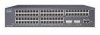
... the utilization meter (UTL) are visible on the Cluster Management Suite (CMS) window and, if the switch is a cluster member, on the CMS Cluster Manager window. The Catalyst 2900 Series XL and Catalyst 3500 Series XL Software Configuration Guide describes how to use CMS to manage standalone or individual... switches and how to use cluster management software to manage switch clusters]. Figure 1-5 Catalyst 2912 XL, 2924 XL, and 2924C XL LEDs 10/100 port LEDs System LED Port mode LEDs MODE 1X 2X 3X 4X 5X 6X 7X...
... the utilization meter (UTL) are visible on the Cluster Management Suite (CMS) window and, if the switch is a cluster member, on the CMS Cluster Manager window. The Catalyst 2900 Series XL and Catalyst 3500 Series XL Software Configuration Guide describes how to use CMS to manage standalone or individual... switches and how to use cluster management software to manage switch clusters]. Figure 1-5 Catalyst 2912 XL, 2924 XL, and 2924C XL LEDs 10/100 port LEDs System LED Port mode LEDs MODE 1X 2X 3X 4X 5X 6X 7X...

Hardware Installation Guide
Page 31
Chapter 1 Product Overview Figure 1-6 Catalyst 2912MF XL, 2924M XL, and 2924M XL DC LEDs 10BASE-FX port LEDs Front-Panel Description 12 1 MODE 2 3 4 5 100BASE-FX 6 7 System LED RPS LED Expansion slot status LED Port mode LED Mode button 48003 78-6461-04 Catalyst 2900 Series XL Hardware Installation Guide 1-11
Chapter 1 Product Overview Figure 1-6 Catalyst 2912MF XL, 2924M XL, and 2924M XL DC LEDs 10BASE-FX port LEDs Front-Panel Description 12 1 MODE 2 3 4 5 100BASE-FX 6 7 System LED RPS LED Expansion slot status LED Port mode LED Mode button 48003 78-6461-04 Catalyst 2900 Series XL Hardware Installation Guide 1-11

Hardware Installation Guide
Page 32
...LED colors and their meanings. For information on the System LED colors during POST, see the "Powering On the Switch and Running POST" section on page 2-24. 1-12 Catalyst 2900 Series XL Hardware Installation Guide 78-6461-04 System is receiving power but is receiving power and functioning ...properly. Front-Panel Description Figure 1-7 Catalyst 2912 LRE XL and 2924 LRE...
...LED colors and their meanings. For information on the System LED colors during POST, see the "Powering On the Switch and Running POST" section on page 2-24. 1-12 Catalyst 2900 Series XL Hardware Installation Guide 78-6461-04 System is receiving power but is receiving power and functioning ...properly. Front-Panel Description Figure 1-7 Catalyst 2912 LRE XL and 2924 LRE...

Hardware Installation Guide
Page 33
... down and after 15 seconds restarts, using power from the RPS. All other Catalyst 2900 XL and Catalyst 3500 XL switches use the Cisco RPS 300 (model PWR300-AC-RPS-N1). The switch goes through its normal boot sequence when it in Ready mode, and the LED should turn green. &#...in the RPS might have failed. RPS is providing power to another device (redundancy has been allocated to the appropriate switch documentation for redundant power system (RPS) descriptions specific for the switch. RPS is connected but not functioning. • The RPS could have failed. • The fan in standby...
... down and after 15 seconds restarts, using power from the RPS. All other Catalyst 2900 XL and Catalyst 3500 XL switches use the Cisco RPS 300 (model PWR300-AC-RPS-N1). The switch goes through its normal boot sequence when it in Ready mode, and the LED should turn green. &#...in the RPS might have failed. RPS is providing power to another device (redundancy has been allocated to the appropriate switch documentation for redundant power system (RPS) descriptions specific for the switch. RPS is connected but not functioning. • The RPS could have failed. • The fan in standby...

Hardware Installation Guide
Page 34
... 1-3 RPS LED on the Catalyst 2912 LRE XL and 2924 LRE XL Switches (continued) Color Solid amber Blinking amber RPS Status The RPS is in standby mode or in a switch has failed, and the RPS is providing power to the switch (redundancy has been allocated to this device). Contact Cisco Systems. The internal power supply in...
... 1-3 RPS LED on the Catalyst 2912 LRE XL and 2924 LRE XL Switches (continued) Color Solid amber Blinking amber RPS Status The RPS is in standby mode or in a switch has failed, and the RPS is providing power to the switch (redundancy has been allocated to this device). Contact Cisco Systems. The internal power supply in...

Hardware Installation Guide
Page 38
... any connected LRE CPE devices. The Catalyst 2900 LRE XL switches do not provide information about the connected Cisco 575 LRE CPE devices. The LEDs on Catalyst 2900 LRE XL switches with Cisco IOS Release 12.0(5.x)WC4 or later do not support Cisco IOS Release 12.0(5.x)WC3. 3. Figure 1-9 Bandwidth Utilization 47293 SYSTEM 10BaseT/100BaseTx RPS 1x 2x 3x...
... any connected LRE CPE devices. The Catalyst 2900 LRE XL switches do not provide information about the connected Cisco 575 LRE CPE devices. The LEDs on Catalyst 2900 LRE XL switches with Cisco IOS Release 12.0(5.x)WC4 or later do not support Cisco IOS Release 12.0(5.x)WC3. 3. Figure 1-9 Bandwidth Utilization 47293 SYSTEM 10BaseT/100BaseTx RPS 1x 2x 3x...

Hardware Installation Guide
Page 39
...Chapter 1 Product Overview Rear-Panel Description Module Slot LEDs Module slot LEDs (shown in Figure 1-6) show the status of a Catalyst 2900 XL and Catalyst 2900 LRE XL switches have an AC power connector, an RPS connector, and an RJ-45 console port. (See Figure 1-10 through Figure ...1-12.) Figure 1-10 Catalyst 2912 XL, 2924 XL, and 2924C XL Rear Panel Fans 47295 11.000A-/1O2R.75A/AT2I0N50G0-2-8400HV~Z AC power connector +5DVSCPIENPCPO@IUWF9TIAEES,[email protected] CONSOLE Redundant power system RJ-45 connector connector 78-6461-04 Catalyst 2900 Series XL Hardware ...
...Chapter 1 Product Overview Rear-Panel Description Module Slot LEDs Module slot LEDs (shown in Figure 1-6) show the status of a Catalyst 2900 XL and Catalyst 2900 LRE XL switches have an AC power connector, an RPS connector, and an RJ-45 console port. (See Figure 1-10 through Figure ...1-12.) Figure 1-10 Catalyst 2912 XL, 2924 XL, and 2924C XL Rear Panel Fans 47295 11.000A-/1O2R.75A/AT2I0N50G0-2-8400HV~Z AC power connector +5DVSCPIENPCPO@IUWF9TIAEES,[email protected] CONSOLE Redundant power system RJ-45 connector connector 78-6461-04 Catalyst 2900 Series XL Hardware ...

Hardware Installation Guide
Page 40
... 48004 100-240V~ 5-3A 50/60Hz MAXIMUM 300W TOTAL OUTPUT DC OUTPUT AC power connector Redundant power system connector CONSOLE RJ-45 connector Figure 1-12 Catalyst 2924M XL and 2912 MF XL Rear Panel Fans CONSOLE RJ-45 connector +5DVSCPINEPCPO@IUWF9TIAEES,[email protected] DC INPUT 21.000A-/11R2.0A0AT/2IN050G0--26400HVZ~ 47296 Redundant power system AC power connector connector The rear panel of the Catalyst 2924M XL DC switch has a DC power connector (also referred to as the terminal block header), an RJ-45...
... 48004 100-240V~ 5-3A 50/60Hz MAXIMUM 300W TOTAL OUTPUT DC OUTPUT AC power connector Redundant power system connector CONSOLE RJ-45 connector Figure 1-12 Catalyst 2924M XL and 2912 MF XL Rear Panel Fans CONSOLE RJ-45 connector +5DVSCPINEPCPO@IUWF9TIAEES,[email protected] DC INPUT 21.000A-/11R2.0A0AT/2IN050G0--26400HVZ~ 47296 Redundant power system AC power connector connector The rear panel of the Catalyst 2924M XL DC switch has a DC power connector (also referred to as the terminal block header), an RJ-45...

Hardware Installation Guide
Page 42
...(one DC output power module for four external devices that has an input supply voltage from -36 to the Cisco Redundant Power System Hardware Installation Guide. 1-22 Catalyst 2900 Series XL Hardware Installation Guide 78-6461-04 Use a one-to the four DC output power modules. For... more information on the Catalyst 2912 XL, 2924C XL, 2924 XL, 2924MF XL, and 2924M XL Switches The Cisco RPS 600 (model PWR600-AC...
...(one DC output power module for four external devices that has an input supply voltage from -36 to the Cisco Redundant Power System Hardware Installation Guide. 1-22 Catalyst 2900 Series XL Hardware Installation Guide 78-6461-04 Use a one-to the four DC output power modules. For... more information on the Catalyst 2912 XL, 2924C XL, 2924 XL, 2924MF XL, and 2924M XL Switches The Cisco RPS 600 (model PWR600-AC...

Hardware Installation Guide
Page 43
... port and adapter pinout information, see the "Connecting to the Console Port" section on the Catalyst 2912 LRE and 2924 LRE XL Switches The RPS is a 300W redundant power system that adapter from Cisco. Note The RPS can support six external network devices and provides power to a PC through the...2-42. 78-6461-04 Catalyst 2900 Series XL Hardware Installation Guide 1-23 Warning Attach only the Cisco RPS (model PWR300-AC-RPS-N1) to the Cisco Redundant Power System 300 Hardware Installation Guide. For more than one switch at a time. If more information on the Cisco RPS 300, refer to ...
... port and adapter pinout information, see the "Connecting to the Console Port" section on the Catalyst 2912 LRE and 2924 LRE XL Switches The RPS is a 300W redundant power system that adapter from Cisco. Note The RPS can support six external network devices and provides power to a PC through the...2-42. 78-6461-04 Catalyst 2900 Series XL Hardware Installation Guide 1-23 Warning Attach only the Cisco RPS (model PWR300-AC-RPS-N1) to the Cisco Redundant Power System 300 Hardware Installation Guide. For more than one switch at a time. If more information on the Cisco RPS 300, refer to ...
Hardware Installation Guide
Page 46
Catalyst 2900 Series XL Hardware Installation Guide 2-2 78-6461-04 Warning Do...Warning The device is connected to the terminals. Warning Before working on any other equipment. Warning To prevent the switch from overheating, do not operate it serves as the main disconnecting device. Warning The plug-socket combination must always... be made first and disconnected last. Metal objects will heat up when connected to work with TN power systems. Warning When installing the unit, the ground connection must be accessible at least 3 inches (7.6 cm) of 113&#...
Catalyst 2900 Series XL Hardware Installation Guide 2-2 78-6461-04 Warning Do...Warning The device is connected to the terminals. Warning Before working on any other equipment. Warning To prevent the switch from overheating, do not operate it serves as the main disconnecting device. Warning The plug-socket combination must always... be made first and disconnected last. Metal objects will heat up when connected to work with TN power systems. Warning When installing the unit, the ground connection must be accessible at least 3 inches (7.6 cm) of 113&#...
Hardware Installation Guide
Page 47
... the power supply when the power cord is connected. Warning Care must be grounded. For systems with a power switch, line voltages are present within the power supply even when the power switch is off and the power cord is different from the power outlet voltage, do not connect... 2 Installation Preparing for Installation Warning This product relies on the phase conductors (all national laws and regulations. 78-6461-04 Catalyst 2900 Series XL Hardware Installation Guide 2-3 Ensure that the host is connected to be given to connecting units to that wiring is connected.
... the power supply when the power cord is connected. Warning Care must be grounded. For systems with a power switch, line voltages are present within the power supply even when the power switch is off and the power cord is different from the power outlet voltage, do not connect... 2 Installation Preparing for Installation Warning This product relies on the phase conductors (all national laws and regulations. 78-6461-04 Catalyst 2900 Series XL Hardware Installation Guide 2-3 Ensure that the host is connected to be given to connecting units to that wiring is connected.