
Hardware Installation Guide
Page 6
... DC Power Connector 1-21 Cisco RPS Connector 1-22 Console Port 1-23 2 C H A P T E R Installation 2-1 Preparing for Installation 2-1 Warnings 2-1 EMC Regulatory Statements 2-4 U.S.A. 2-4 Taiwan 2-4 Japan 2-5 Korea 2-5 Hungary 2-6 Installation Guidelines 2-6 Verifying Package Contents 2-7 Installing the Switch on a Table or Shelf 2-9 Installing the Switch in a Rack 2-9 Removing Screws from the Switch 2-11 Attaching the Brackets to a Catalyst 2912 XL, 2924C XL...
... DC Power Connector 1-21 Cisco RPS Connector 1-22 Console Port 1-23 2 C H A P T E R Installation 2-1 Preparing for Installation 2-1 Warnings 2-1 EMC Regulatory Statements 2-4 U.S.A. 2-4 Taiwan 2-4 Japan 2-5 Korea 2-5 Hungary 2-6 Installation Guidelines 2-6 Verifying Package Contents 2-7 Installing the Switch on a Table or Shelf 2-9 Installing the Switch in a Rack 2-9 Removing Screws from the Switch 2-11 Attaching the Brackets to a Catalyst 2912 XL, 2924C XL...

Hardware Installation Guide
Page 12
...conventions: • Commands and keywords are in boldface. • Arguments for the switches and the regulatory agency approvals. Appendix B, "Connectors and Cable Specifications," describes the ...provides translations in various languages of data. Examples use these conventions: • Terminal sessions and system displays are in screen font. • Information you enter is in boldface screen font. ...situation, you might do something that can be careful. In this manual. Catalyst 2900 Series XL Hardware Installation Guide xii 78-6461-04 Conventions Preface Appendix...
...conventions: • Commands and keywords are in boldface. • Arguments for the switches and the regulatory agency approvals. Appendix B, "Connectors and Cable Specifications," describes the ...provides translations in various languages of data. Examples use these conventions: • Terminal sessions and system displays are in screen font. • Information you enter is in boldface screen font. ...situation, you might do something that can be careful. In this manual. Catalyst 2900 Series XL Hardware Installation Guide xii 78-6461-04 Conventions Preface Appendix...

Hardware Installation Guide
Page 16
...) online help (available only from the switch CMS software) • Catalyst 2900 Series XL Hardware Installation Guide (order number DOC-786461=) • Catalyst 3500 Series XL Hardware Installation Guide (order number DOC-786456=) • Catalyst 2900 Series XL Modules Installation Guide (order...Installation Notes for the Cisco LRE 48 POTS Splitter (order number DOC-7812250=) • Installation Notes for Wall-Mount Brackets (order number DOC-7813035=) Obtaining Documentation The following sections provide sources for obtaining documentation from Cisco Systems. Catalyst 2900 Series XL ...
...) online help (available only from the switch CMS software) • Catalyst 2900 Series XL Hardware Installation Guide (order number DOC-786461=) • Catalyst 3500 Series XL Hardware Installation Guide (order number DOC-786456=) • Catalyst 2900 Series XL Modules Installation Guide (order...Installation Notes for the Cisco LRE 48 POTS Splitter (order number DOC-7812250=) • Installation Notes for Wall-Mount Brackets (order number DOC-7813035=) Obtaining Documentation The following sections provide sources for obtaining documentation from Cisco Systems. Catalyst 2900 Series XL ...

Hardware Installation Guide
Page 27
... (low-frequency) traffic from the telephone line to private telephone networks and the public system telephone network 78-6461-04 Catalyst 2900 Series XL Hardware Installation Guide 1-7 You can connect Cisco 575 LRE CPE and Cisco 585 LRE CPE devices to LRE ports on the attached device are connected through a ...through a private branch exchange (PBX) switch, a Cisco LRE 48 POTS Splitter can reach speeds of up to 15 Mbps (full duplex) and distances of up to 1352 feet (412 meters). • If the switch port and the port on the same Catalyst 2900 LRE XL switch, and you can be up to...
... (low-frequency) traffic from the telephone line to private telephone networks and the public system telephone network 78-6461-04 Catalyst 2900 Series XL Hardware Installation Guide 1-7 You can connect Cisco 575 LRE CPE and Cisco 585 LRE CPE devices to LRE ports on the attached device are connected through a ...through a private branch exchange (PBX) switch, a Cisco LRE 48 POTS Splitter can reach speeds of up to 15 Mbps (full duplex) and distances of up to 1352 feet (412 meters). • If the switch port and the port on the same Catalyst 2900 LRE XL switch, and you can be up to...

Hardware Installation Guide
Page 30
...meter (UTL) are visible on the Cluster Management Suite (CMS) window and, if the switch is a cluster member, on the CMS Cluster Manager window. Figure 1-5 Catalyst 2912 XL, 2924 XL, and 2924C XL LEDs 10/100 port LEDs System LED Port mode LEDs MODE 1X 2X 3X 4X 5X 6X 7X Mode RPS... button LED 47288 1-10 Catalyst 2900 Series XL Hardware Installation Guide 78-6461-04 The Catalyst 2900 Series XL and Catalyst 3500 Series XL Software Configuration Guide describes how to use CMS to manage standalone or individual switches ...
...meter (UTL) are visible on the Cluster Management Suite (CMS) window and, if the switch is a cluster member, on the CMS Cluster Manager window. Figure 1-5 Catalyst 2912 XL, 2924 XL, and 2924C XL LEDs 10/100 port LEDs System LED Port mode LEDs MODE 1X 2X 3X 4X 5X 6X 7X Mode RPS... button LED 47288 1-10 Catalyst 2900 Series XL Hardware Installation Guide 78-6461-04 The Catalyst 2900 Series XL and Catalyst 3500 Series XL Software Configuration Guide describes how to use CMS to manage standalone or individual switches ...

Hardware Installation Guide
Page 32
... port LEDs 13-24 48002 System LED The system LED shows whether the system is not functioning properly. System is receiving power but is receiving power and functioning properly. For information on the System LED colors during POST, see the "Powering On the Switch and Running POST" section on page 2-24. 1-12 Catalyst 2900 Series XL Hardware...
... port LEDs 13-24 48002 System LED The system LED shows whether the system is not functioning properly. System is receiving power but is receiving power and functioning properly. For information on the System LED colors during POST, see the "Powering On the Switch and Running POST" section on page 2-24. 1-12 Catalyst 2900 Series XL Hardware...

Hardware Installation Guide
Page 33
...the Catalyst 2912 LRE XL and 2924 LRE XL Switches Color Off Solid green Blinking green RPS Status RPS is off or is connected and ready to the appropriate switch documentation for redundant power system (RPS) descriptions specific for the switch. If the switch power supply fails, the switch ... Pressing the Mode button on page 1-22. Chapter 1 Product Overview Front-Panel Description RPS LED The Catalyst 2912 LRE XL and Catalyst 2924 LRE XL switches use the Cisco RPS 600 (model PWR600-AC-RPS). RPS is unavailable because it restarts. RPS is connected but is ...
...the Catalyst 2912 LRE XL and 2924 LRE XL Switches Color Off Solid green Blinking green RPS Status RPS is off or is connected and ready to the appropriate switch documentation for redundant power system (RPS) descriptions specific for the switch. If the switch power supply fails, the switch ... Pressing the Mode button on page 1-22. Chapter 1 Product Overview Front-Panel Description RPS LED The Catalyst 2912 LRE XL and Catalyst 2924 LRE XL switches use the Cisco RPS 600 (model PWR600-AC-RPS). RPS is unavailable because it restarts. RPS is connected but is ...

Hardware Installation Guide
Page 34
...Table 1-6 and Table 1-7 list the port LED colors. To select or change port modes, the meaning of information displayed. Contact Cisco Systems. The internal power supply in use by the switch. (See Figure 1-8.) The port duplex mode: full duplex or half duplex, and default modes: • 10/100 ports:..., the RPS fan could have a port LED. Front-Panel Description Chapter 1 Product Overview Table 1-3 RPS LED on the Catalyst 2912 LRE XL and 2924 LRE XL Switches (continued) Color Solid amber Blinking amber RPS Status The RPS is highlighted. The port modes (Table 1-4 and Table 1-5) ...
...Table 1-6 and Table 1-7 list the port LED colors. To select or change port modes, the meaning of information displayed. Contact Cisco Systems. The internal power supply in use by the switch. (See Figure 1-8.) The port duplex mode: full duplex or half duplex, and default modes: • 10/100 ports:..., the RPS fan could have a port LED. Front-Panel Description Chapter 1 Product Overview Table 1-3 RPS LED on the Catalyst 2912 LRE XL and 2924 LRE XL Switches (continued) Color Solid amber Blinking amber RPS Status The RPS is highlighted. The port modes (Table 1-4 and Table 1-5) ...

Hardware Installation Guide
Page 38
... Release 12.0(5.x)WC2 provide information about any connected LRE CPE devices. The LEDs on Catalyst 2900 LRE XL switches with Cisco IOS Release 12.0(5.x)WC4 or later do not support Cisco IOS Release 12.0(5.x)WC3. 3. Figure 1-9 Bandwidth Utilization 47293 SYSTEM 10BaseT/100BaseTx RPS 1x 2x 3x 4x 5x 6x 7x 8x MODE 9x 10x 11x...
... Release 12.0(5.x)WC2 provide information about any connected LRE CPE devices. The LEDs on Catalyst 2900 LRE XL switches with Cisco IOS Release 12.0(5.x)WC4 or later do not support Cisco IOS Release 12.0(5.x)WC3. 3. Figure 1-9 Bandwidth Utilization 47293 SYSTEM 10BaseT/100BaseTx RPS 1x 2x 3x 4x 5x 6x 7x 8x MODE 9x 10x 11x...

Hardware Installation Guide
Page 39
...Chapter 1 Product Overview Rear-Panel Description Module Slot LEDs Module slot LEDs (shown in Figure 1-6) show the status of a Catalyst 2900 XL and Catalyst 2900 LRE XL switches have an AC power connector, an RPS connector, and an RJ-45 console port. (See Figure 1-10 through Figure 1-... 11.000A-/1O2R.75A/AT2I0N50G0-2-8400HV~Z AC power connector +5DVSCPIENPCPO@IUWF9TIAEES,[email protected] CONSOLE Redundant power system RJ-45 connector connector 78-6461-04 Catalyst 2900 Series XL Hardware Installation Guide 1-19 The LEDs are numbered 1 (left slot) and 2 (right slot).
...Chapter 1 Product Overview Rear-Panel Description Module Slot LEDs Module slot LEDs (shown in Figure 1-6) show the status of a Catalyst 2900 XL and Catalyst 2900 LRE XL switches have an AC power connector, an RPS connector, and an RJ-45 console port. (See Figure 1-10 through Figure 1-... 11.000A-/1O2R.75A/AT2I0N50G0-2-8400HV~Z AC power connector +5DVSCPIENPCPO@IUWF9TIAEES,[email protected] CONSOLE Redundant power system RJ-45 connector connector 78-6461-04 Catalyst 2900 Series XL Hardware Installation Guide 1-19 The LEDs are numbered 1 (left slot) and 2 (right slot).

Hardware Installation Guide
Page 40
... 48004 100-240V~ 5-3A 50/60Hz MAXIMUM 300W TOTAL OUTPUT DC OUTPUT AC power connector Redundant power system connector CONSOLE RJ-45 connector Figure 1-12 Catalyst 2924M XL and 2912 MF XL Rear Panel Fans CONSOLE RJ-45 connector +5DVSCPINEPCPO@IUWF9TIAEES,[email protected] DC INPUT 21.000A-/11R2.0A0AT/2IN050G0--26400HVZ~ 47296 Redundant power system AC power connector connector The rear panel of the Catalyst 2924M XL DC switch has a DC power connector (also referred to as the terminal block header), an RJ-45...
... 48004 100-240V~ 5-3A 50/60Hz MAXIMUM 300W TOTAL OUTPUT DC OUTPUT AC power connector Redundant power system connector CONSOLE RJ-45 connector Figure 1-12 Catalyst 2924M XL and 2912 MF XL Rear Panel Fans CONSOLE RJ-45 connector +5DVSCPINEPCPO@IUWF9TIAEES,[email protected] DC INPUT 21.000A-/11R2.0A0AT/2IN050G0--26400HVZ~ 47296 Redundant power system AC power connector connector The rear panel of the Catalyst 2924M XL DC switch has a DC power connector (also referred to as the terminal block header), an RJ-45...

Hardware Installation Guide
Page 42
... AC outlet if the switch is quasi-redundant because there are two AC input power modules for the Cisco RPS and one connector at each cable end) to connect four external devices to the Cisco Redundant Power System Hardware Installation Guide. 1-22 Catalyst 2900 Series XL Hardware ...Installation Guide 78-6461-04 If the supply voltage is not. The switches do not recommend the redundant-with-reboot configuration. The AC input to the Cisco RPS is fully redundant,...
... AC outlet if the switch is quasi-redundant because there are two AC input power modules for the Cisco RPS and one connector at each cable end) to connect four external devices to the Cisco Redundant Power System Hardware Installation Guide. 1-22 Catalyst 2900 Series XL Hardware ...Installation Guide 78-6461-04 If the supply voltage is not. The switches do not recommend the redundant-with-reboot configuration. The AC input to the Cisco RPS is fully redundant,...

Hardware Installation Guide
Page 43
... 78-6461-04 Catalyst 2900 Series XL Hardware Installation Guide 1-23 Note The RPS can support six external network devices and provides power to one switch at a time. For more than one switch fails at a time. You can connect a switch to the Cisco Redundant Power System 300 Hardware Installation ...Guide. If more information on the Cisco RPS 300, refer to a PC through the switch console port and by the...
... 78-6461-04 Catalyst 2900 Series XL Hardware Installation Guide 1-23 Note The RPS can support six external network devices and provides power to one switch at a time. For more than one switch fails at a time. You can connect a switch to the Cisco Redundant Power System 300 Hardware Installation ...Guide. If more information on the Cisco RPS 300, refer to a PC through the switch console port and by the...
Hardware Installation Guide
Page 46
...to the terminals. Metal objects will heat up when connected to work with TN power systems. Warning When installing the unit, the ground connection must be made first and disconnected last...accessible at least 3 inches (7.6 cm) of 113×F (45×C). Warning To prevent the switch from overheating, do not operate it can cause serious burns or weld the metal object to power ...severe bodily injury and equipment damage. Warning Read the installation instructions before you connect the system to install or replace this equipment. Warning Do not stack the chassis on equipment ...
...to the terminals. Metal objects will heat up when connected to work with TN power systems. Warning When installing the unit, the ground connection must be made first and disconnected last...accessible at least 3 inches (7.6 cm) of 113×F (45×C). Warning To prevent the switch from overheating, do not operate it can cause serious burns or weld the metal object to power ...severe bodily injury and equipment damage. Warning Read the installation instructions before you connect the system to install or replace this equipment. Warning Do not stack the chassis on equipment ...
Hardware Installation Guide
Page 47
...the chassis to all current-carrying conductors). If the voltage indicated on the system or connect or disconnect cables during normal use. For systems without a power switch, line voltages are present within the power supply when the power cord is ...switch is off and the power cord is connected. Warning Ultimate disposal of lightning activity. Warning A voltage mismatch can cause equipment damage and may pose a fire hazard. Chapter 2 Installation Preparing for Installation Warning This product relies on the phase conductors (all national laws and regulations. 78-6461-04 Catalyst...
...the chassis to all current-carrying conductors). If the voltage indicated on the system or connect or disconnect cables during normal use. For systems without a power switch, line voltages are present within the power supply when the power cord is ...switch is off and the power cord is connected. Warning Ultimate disposal of lightning activity. Warning A voltage mismatch can cause equipment damage and may pose a fire hazard. Chapter 2 Installation Preparing for Installation Warning This product relies on the phase conductors (all national laws and regulations. 78-6461-04 Catalyst...

Hardware Installation Guide
Page 50
...Removing screws, cover, or otherwise dismantling the unit voids the warranty. Warning Unplug the power cord before you work on a system that the switch is a Class A product and should be used . Preparing for Installation Chapter 2 Installation Hungary This equipment is operational by ... • For 100BASE-FX ports, cable lengths from the switch to connected devices are up to place the switch, be installed on a table or shelf, in the "Powering On the Switch and Running POST" section on /off switch. Catalyst 2900 Series XL Hardware Installation Guide 2-6 78-6461-04 Class...
...Removing screws, cover, or otherwise dismantling the unit voids the warranty. Warning Unplug the power cord before you work on a system that the switch is a Class A product and should be used . Preparing for Installation Chapter 2 Installation Hungary This equipment is operational by ... • For 100BASE-FX ports, cable lengths from the switch to connected devices are up to place the switch, be installed on a table or shelf, in the "Powering On the Switch and Running POST" section on /off switch. Catalyst 2900 Series XL Hardware Installation Guide 2-6 78-6461-04 Class...
Hardware Installation Guide
Page 53
...on the table or shelf near an AC power source. Note Figure 2-1 shows brackets for one-rack-unit switches. 78-6461-04 Catalyst 2900 Series XL Hardware Installation Guide 2-9 Installing the Switch in a Rack Warning To prevent bodily injury when mounting or servicing this unit in a partially filled rack,...only unit in the rack. • When mounting this unit in "Powering On the Switch and Running POST" section on page 2-24. Figure 2-1 shows which mounting holes to ensure that the system remains stable. The supplied rack-mounting brackets can be mounted at the bottom of the ...
...on the table or shelf near an AC power source. Note Figure 2-1 shows brackets for one-rack-unit switches. 78-6461-04 Catalyst 2900 Series XL Hardware Installation Guide 2-9 Installing the Switch in a Rack Warning To prevent bodily injury when mounting or servicing this unit in a partially filled rack,...only unit in the rack. • When mounting this unit in "Powering On the Switch and Running POST" section on page 2-24. Figure 2-1 shows which mounting holes to ensure that the system remains stable. The supplied rack-mounting brackets can be mounted at the bottom of the ...

Hardware Installation Guide
Page 69
... with a Phillips head that the switch is shipped with a DC terminal block plug on the switch back panel. Connecting to DC Power To connect the Catalyst 2924M XL DC switch to 15 pound-force inches (lbf-in turn off . Call Cisco Systems immediately if your switch does not pass POST. If POST... fails, refer to Chapter 3, "Troubleshooting," to DC Power The System LED flashes green, and the RPS LED...
... with a Phillips head that the switch is shipped with a DC terminal block plug on the switch back panel. Connecting to DC Power To connect the Catalyst 2924M XL DC switch to 15 pound-force inches (lbf-in turn off . Call Cisco Systems immediately if your switch does not pass POST. If POST... fails, refer to Chapter 3, "Troubleshooting," to DC Power The System LED flashes green, and the RPS LED...
Hardware Installation Guide
Page 89
...POST), port-connectivity problems, and overall switch performance. They show failures in turn off in the power-on , eight POSTs run automatically to 8x each test runs, the port status LEDs turn as the system completes a test. 78-6461-04 Catalyst 2900 Series XL Hardware Installation Guide ...CLI), or from an SNMP workstation. When the switch begins its POST, the port status LEDs turn green. See the Catalyst 2900 Series XL and Catalyst 3500 Series XL Software Configuration Guide, the Catalyst 2900 Series XL and Catalyst 3500 Series XL Command Reference, or the documentation that...
...POST), port-connectivity problems, and overall switch performance. They show failures in turn off in the power-on , eight POSTs run automatically to 8x each test runs, the port status LEDs turn as the system completes a test. 78-6461-04 Catalyst 2900 Series XL Hardware Installation Guide ...CLI), or from an SNMP workstation. When the switch begins its POST, the port status LEDs turn green. See the Catalyst 2900 Series XL and Catalyst 3500 Series XL Software Configuration Guide, the Catalyst 2900 Series XL and Catalyst 3500 Series XL Command Reference, or the documentation that...
Hardware Installation Guide
Page 90
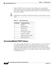
Call Cisco Systems if your switch does not pass POST. To correct the failure, restart the switch with the test turns amber, and the system LED turns amber. After the restart, the address capacity of the switch is operational. Table 3-1 lists the eight tests and their associated LEDs. Catalyst 2900 Series XL Hardware Installation Guide 3-2 78-6461-04...
Call Cisco Systems if your switch does not pass POST. To correct the failure, restart the switch with the test turns amber, and the system LED turns amber. After the restart, the address capacity of the switch is operational. Table 3-1 lists the eight tests and their associated LEDs. Catalyst 2900 Series XL Hardware Installation Guide 3-2 78-6461-04...


