
Hardware Installation Guide
Page 6
... DC Power Connector 1-21 Cisco RPS Connector 1-22 Console Port 1-23 2 C H A P T E R Installation 2-1 Preparing for Installation 2-1 Warnings 2-1 EMC Regulatory Statements 2-4 U.S.A. 2-4 Taiwan 2-4 Japan 2-5 Korea 2-5 Hungary 2-6 Installation Guidelines 2-6 Verifying Package Contents 2-7 Installing the Switch on a Table or Shelf 2-9 Installing the Switch in a Rack 2-9 Removing Screws from the Switch 2-11 Attaching the Brackets to a Catalyst 2912 XL, 2924C XL...
... DC Power Connector 1-21 Cisco RPS Connector 1-22 Console Port 1-23 2 C H A P T E R Installation 2-1 Preparing for Installation 2-1 Warnings 2-1 EMC Regulatory Statements 2-4 U.S.A. 2-4 Taiwan 2-4 Japan 2-5 Korea 2-5 Hungary 2-6 Installation Guidelines 2-6 Verifying Package Contents 2-7 Installing the Switch on a Table or Shelf 2-9 Installing the Switch in a Rack 2-9 Removing Screws from the Switch 2-11 Attaching the Brackets to a Catalyst 2912 XL, 2924C XL...

Hardware Installation Guide
Page 7
...18 Attaching the Optional Cable Guide 2-19 Installing the Switch on a Wall 2-20 Attaching the Brackets to the Switch 2-21 Mounting the Switch to a Wall 2-22 Powering On the Switch and Running POST 2-24 Connecting to DC Power 2-25 Preparing for Installation 2-25 Grounding the Switch 2-26 Wiring the DC-Input Power Source 2-29... Correcting Module POST Failures 3-2 Diagnosing Problems 3-3 Technical Specifications A-1 Connectors and Cable Specifications B-1 Connector Specifications B-1 10/100 Ports B-1 100BASE-FX Ports B-2 Contents 78-6461-04 Catalyst 2900 Series XL Hardware Installation Guide vii
...18 Attaching the Optional Cable Guide 2-19 Installing the Switch on a Wall 2-20 Attaching the Brackets to the Switch 2-21 Mounting the Switch to a Wall 2-22 Powering On the Switch and Running POST 2-24 Connecting to DC Power 2-25 Preparing for Installation 2-25 Grounding the Switch 2-26 Wiring the DC-Input Power Source 2-29... Correcting Module POST Failures 3-2 Diagnosing Problems 3-3 Technical Specifications A-1 Connectors and Cable Specifications B-1 Connector Specifications B-1 10/100 Ports B-1 100BASE-FX Ports B-2 Contents 78-6461-04 Catalyst 2900 Series XL Hardware Installation Guide vii

Hardware Installation Guide
Page 9
INDEX Class 1 Laser Product Warning C-22 Laser Beam Exposure Warning C-23 No On/Off Switch Warning C-24 Chassis Warning-Rack-Mounting and Servicing C-25 Reinforced Insulation Warning C-29 LAN Connections Only Warning C-30 No Field-Replaceable Units Warning C-31 Installation ... Equipment Warning C-36 Ground Connection Warning C-37 Qualified Personnel Warning C-38 DC Power Disconnection Warning C-39 Exposed Wire Lead Warning C-41 Contents 78-6461-04 Catalyst 2900 Series XL Hardware Installation Guide ix
INDEX Class 1 Laser Product Warning C-22 Laser Beam Exposure Warning C-23 No On/Off Switch Warning C-24 Chassis Warning-Rack-Mounting and Servicing C-25 Reinforced Insulation Warning C-29 LAN Connections Only Warning C-30 No Field-Replaceable Units Warning C-31 Installation ... Equipment Warning C-36 Ground Connection Warning C-37 Qualified Personnel Warning C-38 DC Power Disconnection Warning C-39 Exposed Wire Lead Warning C-41 Contents 78-6461-04 Catalyst 2900 Series XL Hardware Installation Guide ix

Hardware Installation Guide
Page 11
... how to identify and resolve some of the problems that you are familiar with the concepts and terminology of Catalyst 2900 series XL switches. Purpose The Catalyst 2900 Series XL Hardware Installation Guide documents the hardware features of Ethernet and local area networking. We assume that might arise when you are installing ...
... how to identify and resolve some of the problems that you are familiar with the concepts and terminology of Catalyst 2900 series XL switches. Purpose The Catalyst 2900 Series XL Hardware Installation Guide documents the hardware features of Ethernet and local area networking. We assume that might arise when you are installing ...

Hardware Installation Guide
Page 12
...; Commands and keywords are in boldface. • Arguments for the switches and the regulatory agency approvals. Conventions This guide uses the following conventions and symbols: Note Means reader take note. Catalyst 2900 Series XL Hardware Installation Guide xii 78-6461-04 In this ...connectors, cables, and adapters that could result in this manual. Notes contain helpful suggestions or references to the switch. Conventions Preface Appendix A, "Technical Specifications," lists the physical and environmental specifications for which you supply values are in italic.
...; Commands and keywords are in boldface. • Arguments for the switches and the regulatory agency approvals. Conventions This guide uses the following conventions and symbols: Note Means reader take note. Catalyst 2900 Series XL Hardware Installation Guide xii 78-6461-04 In this ...connectors, cables, and adapters that could result in this manual. Notes contain helpful suggestions or references to the switch. Conventions Preface Appendix A, "Technical Specifications," lists the physical and environmental specifications for which you supply values are in italic.

Hardware Installation Guide
Page 15
...vilket medföljer denna anordning. Before installing, configuring, or upgrading the switch, refer to the release notes on Cisco.com) Note Switch requirements and procedures for the latest information. 78-6461-04 Catalyst 2900 Series XL Hardware Installation Guide xv Este símbolo de aviso significa... in the "Obtaining Documentation" section on page xvi. • Release Notes for the Catalyst 2900 Series XL and Catalyst 3500 Series XL Switches (not orderable but is available on Cisco.com for initial configurations and software upgrades tend to change and therefore appear only in the...
...vilket medföljer denna anordning. Before installing, configuring, or upgrading the switch, refer to the release notes on Cisco.com) Note Switch requirements and procedures for the latest information. 78-6461-04 Catalyst 2900 Series XL Hardware Installation Guide xv Este símbolo de aviso significa... in the "Obtaining Documentation" section on page xvi. • Release Notes for the Catalyst 2900 Series XL and Catalyst 3500 Series XL Switches (not orderable but is available on Cisco.com for initial configurations and software upgrades tend to change and therefore appear only in the...

Hardware Installation Guide
Page 16
... online help (available only from the switch CMS software) • Catalyst 2900 Series XL Hardware Installation Guide (order number DOC-786461=) • Catalyst 3500 Series XL Hardware Installation Guide (order number DOC-786456=) • Catalyst 2900 Series XL Modules Installation Guide (order...1000BASE-T Gigabit Interface Converter Installation Note (not orderable but is available on Cisco.com) • Catalyst GigaStack Gigabit Interface Converter Hardware Installation Guide (order number DOC-786460=) • Cisco LRE CPE Hardware Installation Guide (order number DOC-7811469=) • ...
... online help (available only from the switch CMS software) • Catalyst 2900 Series XL Hardware Installation Guide (order number DOC-786461=) • Catalyst 3500 Series XL Hardware Installation Guide (order number DOC-786456=) • Catalyst 2900 Series XL Modules Installation Guide (order...1000BASE-T Gigabit Interface Converter Installation Note (not orderable but is available on Cisco.com) • Catalyst GigaStack Gigabit Interface Converter Hardware Installation Guide (order number DOC-786460=) • Cisco LRE CPE Hardware Installation Guide (order number DOC-7811469=) • ...

Hardware Installation Guide
Page 21
... Descriptions of the front and rear panels • Descriptions of the LEDs Features The switches are stackable 10/100 Ethernet switches to 4921 feet (1500 meters). The Catalyst 2900 XL switches have these topics that allows an Ethernet network to reach distances up to which you ...can be deployed as servers, routers, and other network devices. The switches can connect workstations, Cisco IP Phones, and other network devices such as backbone switches, aggregating...
... Descriptions of the front and rear panels • Descriptions of the LEDs Features The switches are stackable 10/100 Ethernet switches to 4921 feet (1500 meters). The Catalyst 2900 XL switches have these topics that allows an Ethernet network to reach distances up to which you ...can be deployed as servers, routers, and other network devices. The switches can connect workstations, Cisco IP Phones, and other network devices such as backbone switches, aggregating...

Hardware Installation Guide
Page 22
...converter • On the Catalyst 2912 LRE XL and 2924 LRE XL switches, up to 24 LRE ports through one RJ-21 connector and hot swapping capability with the Cisco LRE customer premises equipment (CPE) devices • Supports up to 2048 MAC addresses on the Catalyst 2924 XL, 2924C XL,... and 2912 XL switches • Supports up to 8192 MAC addresses on the Catalyst 2924M XL, Catalyst 2924M XL DC and Catalyst 2912MF XL switches Figure 1-1 shows ...
...converter • On the Catalyst 2912 LRE XL and 2924 LRE XL switches, up to 24 LRE ports through one RJ-21 connector and hot swapping capability with the Cisco LRE customer premises equipment (CPE) devices • Supports up to 2048 MAC addresses on the Catalyst 2924 XL, 2924C XL,... and 2912 XL switches • Supports up to 8192 MAC addresses on the Catalyst 2924M XL, Catalyst 2924M XL DC and Catalyst 2912MF XL switches Figure 1-1 shows ...

Hardware Installation Guide
Page 23
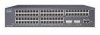
Chapter 1 Product Overview Figure 1-1 Catalyst 2900 Series XL Switches Version Number Description WS-C2912-LRE-XL 4 fixed autosensing 10/100 ports INPUT OUTPUT PWR PWR RESET TEMP FAN 9X 10X 11X 12X 12 LRE ports Cisco RPS 300 WS-C2924-LRE-XL 4 fixed autosensing 10/100 ports 24 LRE ports INPUT OUTPUT PWR PWR... 4 5 100BASE-FX 6 7 8 9 10 11 12 WS-C2924M-XL WS-C2924M-XLEM-DC 24 fixed autosensing 10/100 ports 2 expansion slots 12 MODE 1X 2X 3X Catalyst 2900 SERIES XL 4X 5X 6X 7X 8X 9X 10X 11X 100BaseFX 12X 13X 14X 15X 16X 17X 18X 19X 20X 21X 22X 23X 24X...
Chapter 1 Product Overview Figure 1-1 Catalyst 2900 Series XL Switches Version Number Description WS-C2912-LRE-XL 4 fixed autosensing 10/100 ports INPUT OUTPUT PWR PWR RESET TEMP FAN 9X 10X 11X 12X 12 LRE ports Cisco RPS 300 WS-C2924-LRE-XL 4 fixed autosensing 10/100 ports 24 LRE ports INPUT OUTPUT PWR PWR... 4 5 100BASE-FX 6 7 8 9 10 11 12 WS-C2924M-XL WS-C2924M-XLEM-DC 24 fixed autosensing 10/100 ports 2 expansion slots 12 MODE 1X 2X 3X Catalyst 2900 SERIES XL 4X 5X 6X 7X 8X 9X 10X 11X 100BaseFX 12X 13X 14X 15X 16X 17X 18X 19X 20X 21X 22X 23X 24X...

Hardware Installation Guide
Page 24
... or Microsoft Internet Explorer. For more information about CMS, the CLI, and SNMP refer to support desktop-switching features. Catalyst 2900 Series XL Hardware Installation Guide 1-4 78-6461-04 Front-Panel Description Depending on the switch. All switches have up to twenty-four 10/100 ports (See Figure 1-2), up to twelve 100BASE-FX ports...
... or Microsoft Internet Explorer. For more information about CMS, the CLI, and SNMP refer to support desktop-switching features. Catalyst 2900 Series XL Hardware Installation Guide 1-4 78-6461-04 Front-Panel Description Depending on the switch. All switches have up to twenty-four 10/100 ports (See Figure 1-2), up to twelve 100BASE-FX ports...

Hardware Installation Guide
Page 26
... connectors and Category 3, 4, or 5 cabling • 100BASE-TX-compatible devices, such as high-speed workstations, Cisco IP Phones, servers, hubs, routers, and other switches through , twisted-pair cable. Unlike the 3524-PWR XL switch, the Catalyst 2900 XL switches do not provide inline power. Pinouts for 100BASE-TX traffic. When set for speed and duplex...
... connectors and Category 3, 4, or 5 cabling • 100BASE-TX-compatible devices, such as high-speed workstations, Cisco IP Phones, servers, hubs, routers, and other switches through , twisted-pair cable. Unlike the 3524-PWR XL switch, the Catalyst 2900 XL switches do not provide inline power. Pinouts for 100BASE-TX traffic. When set for speed and duplex...

Hardware Installation Guide
Page 27
... 78-6461-04 Catalyst 2900 Series XL Hardware Installation Guide 1-7 Chapter 1 Product Overview Front-Panel Description 100BASE-FX Ports The 100BASE-FX ports use the same cabling as LRE traffic, the LRE port must be connected to the patch panel through a private branch exchange (PBX) switch, a Cisco LRE 48 POTS ...up to 1352 feet (412 meters). • If the switch port and the port on the same Catalyst 2900 LRE XL switch, and you can reach speeds of up to 15 Mbps (full duplex) and distances of up to the Cisco LRE CPE Hardware Installation Guide. or 62.5/125-micron multimode fiber...
... 78-6461-04 Catalyst 2900 Series XL Hardware Installation Guide 1-7 Chapter 1 Product Overview Front-Panel Description 100BASE-FX Ports The 100BASE-FX ports use the same cabling as LRE traffic, the LRE port must be connected to the patch panel through a private branch exchange (PBX) switch, a Cisco LRE 48 POTS ...up to 1352 feet (412 meters). • If the switch port and the port on the same Catalyst 2900 LRE XL switch, and you can reach speeds of up to 15 Mbps (full duplex) and distances of up to the Cisco LRE CPE Hardware Installation Guide. or 62.5/125-micron multimode fiber...

Hardware Installation Guide
Page 28
... not required, a splitter is managed through the switch management interfaces. Table 1-1 lists the modules that use the 0 to the patch panel. Note If a connection to the Installation Notes for the Catalyst 2900 XL hot-swappable modules. Note Cisco Long-Reach Ethernet (LRE) products are for the Cisco LRE 48 POTS Splitter. For more information...
... not required, a splitter is managed through the switch management interfaces. Table 1-1 lists the modules that use the 0 to the patch panel. Note If a connection to the Installation Notes for the Catalyst 2900 XL hot-swappable modules. Note Cisco Long-Reach Ethernet (LRE) products are for the Cisco LRE 48 POTS Splitter. For more information...

Hardware Installation Guide
Page 29
...78-6461-04 You can start the module by each port LED. A power-on expansion modules for the Catalyst 2900 Series XL and Catalyst 3500 Series XL Switches. After the restart, the switch address capacity is working properly before it starts forwarding packets. Refer to 2048 MAC addresses. Changing a port mode... (GBIC) devices. If you install one of the LEDs and the Mode button that you insert them in a 2924M XL or Catalyst 2912MF XL switch (both supporting 8192 MAC addresses), the module fails POST. Note Modules WS-X2914-XL and WS-X2922-XL support 2048 MAC addresses.
...78-6461-04 You can start the module by each port LED. A power-on expansion modules for the Catalyst 2900 Series XL and Catalyst 3500 Series XL Switches. After the restart, the switch address capacity is working properly before it starts forwarding packets. Refer to 2048 MAC addresses. Changing a port mode... (GBIC) devices. If you install one of the LEDs and the Mode button that you insert them in a 2924M XL or Catalyst 2912MF XL switch (both supporting 8192 MAC addresses), the module fails POST. Note Modules WS-X2914-XL and WS-X2922-XL support 2048 MAC addresses.

Hardware Installation Guide
Page 30
...section except the utilization meter (UTL) are visible on the Cluster Management Suite (CMS) window and, if the switch is a cluster member, on the CMS Cluster Manager window. Figure 1-5 Catalyst 2912 XL, 2924 XL, and 2924C XL LEDs 10/100 port LEDs System LED Port mode LEDs MODE 1X 2X... 6X 7X Mode RPS button LED 47288 1-10 Catalyst 2900 Series XL Hardware Installation Guide 78-6461-04 The Catalyst 2900 Series XL and Catalyst 3500 Series XL Software Configuration Guide describes how to use CMS to manage standalone or individual switches and how to use cluster management software to manage...
...section except the utilization meter (UTL) are visible on the Cluster Management Suite (CMS) window and, if the switch is a cluster member, on the CMS Cluster Manager window. Figure 1-5 Catalyst 2912 XL, 2924 XL, and 2924C XL LEDs 10/100 port LEDs System LED Port mode LEDs MODE 1X 2X... 6X 7X Mode RPS button LED 47288 1-10 Catalyst 2900 Series XL Hardware Installation Guide 78-6461-04 The Catalyst 2900 Series XL and Catalyst 3500 Series XL Software Configuration Guide describes how to use CMS to manage standalone or individual switches and how to use cluster management software to manage...

Hardware Installation Guide
Page 32
... Color Off Green Amber System Status System is operating normally. For information on the System LED colors during POST, see the "Powering On the Switch and Running POST" section on page 2-24. 1-12 Catalyst 2900 Series XL Hardware Installation Guide 78-6461-04 System is not powered up. Front-Panel Description Figure... 1-7 Catalyst 2912 LRE XL and 2924 LRE XL LEDs 10/100 port LEDs Chapter 1 Product Overview SYSTEM RPS MODE LRE STAT DUPLX SPEED Mode button 1X ...
... Color Off Green Amber System Status System is operating normally. For information on the System LED colors during POST, see the "Powering On the Switch and Running POST" section on page 2-24. 1-12 Catalyst 2900 Series XL Hardware Installation Guide 78-6461-04 System is not powered up. Front-Panel Description Figure... 1-7 Catalyst 2912 LRE XL and 2924 LRE XL LEDs 10/100 port LEDs Chapter 1 Product Overview SYSTEM RPS MODE LRE STAT DUPLX SPEED Mode button 1X ...

Hardware Installation Guide
Page 33
... The fan in standby mode. RPS is not installed. If the switch power supply fails, the switch powers down and after 15 seconds restarts, using power from the RPS. All other Catalyst 2900 XL and Catalyst 3500 XL switches use the Cisco RPS 300 (model PWR300-AC-RPS-N1). RPS is not a ...13 Table 1-3 RPS LED on page 1-22. Chapter 1 Product Overview Front-Panel Description RPS LED The Catalyst 2912 LRE XL and Catalyst 2924 LRE XL switches use the Cisco RPS 600 (model PWR600-AC-RPS). The switch goes through its normal boot sequence when it is off or not properly connected.
... The fan in standby mode. RPS is not installed. If the switch power supply fails, the switch powers down and after 15 seconds restarts, using power from the RPS. All other Catalyst 2900 XL and Catalyst 3500 XL switches use the Cisco RPS 300 (model PWR300-AC-RPS-N1). RPS is not a ...13 Table 1-3 RPS LED on page 1-22. Chapter 1 Product Overview Front-Panel Description RPS LED The Catalyst 2912 LRE XL and Catalyst 2924 LRE XL switches use the Cisco RPS 600 (model PWR600-AC-RPS). The switch goes through its normal boot sequence when it is off or not properly connected.

Hardware Installation Guide
Page 34
... Mode button until the desired mode is the default mode. This is highlighted. Contact Cisco Systems. The internal power supply in a switch has failed, and the RPS is in standby mode or in use by the switch. (See Figure 1-8.) The port duplex mode: full duplex or half duplex, and ...green. Front-Panel Description Chapter 1 Product Overview Table 1-3 RPS LED on the Catalyst 2912 LRE XL and 2924 LRE XL Switches (continued) Color Solid amber Blinking amber RPS Status The RPS is providing power to the switch (redundancy has been allocated to this device). If it does not, the ...
... Mode button until the desired mode is the default mode. This is highlighted. Contact Cisco Systems. The internal power supply in a switch has failed, and the RPS is in standby mode or in use by the switch. (See Figure 1-8.) The port duplex mode: full duplex or half duplex, and ...green. Front-Panel Description Chapter 1 Product Overview Table 1-3 RPS LED on the Catalyst 2912 LRE XL and 2924 LRE XL Switches (continued) Color Solid amber Blinking amber RPS Status The RPS is providing power to the switch (redundancy has been allocated to this device). If it does not, the ...

Hardware Installation Guide
Page 35
...speed: 10 or 100 Mbps. Note When the LRE mode is half duplex. Ethernet link status of the LRE ports on the Catalyst 2912 LRE XL and Catalyst 2924 LRE XL switches. The port duplex mode: full duplex or half duplex. Chapter 1 Product Overview Front-Panel Description Table 1-5 Port Mode LEDs ...on Catalyst 2912 LRE XL and 2924 LRE XL Switches Mode LED LRE STAT DUPLX SPEED Port Mode LRE link status Port status Port duplex mode Port speed Description Long-Reach Ethernet (...
...speed: 10 or 100 Mbps. Note When the LRE mode is half duplex. Ethernet link status of the LRE ports on the Catalyst 2912 LRE XL and Catalyst 2924 LRE XL switches. The port duplex mode: full duplex or half duplex. Chapter 1 Product Overview Front-Panel Description Table 1-5 Port Mode LEDs ...on Catalyst 2912 LRE XL and 2924 LRE XL Switches Mode LED LRE STAT DUPLX SPEED Port Mode LRE link status Port status Port duplex mode Port speed Description Long-Reach Ethernet (...


