
Hardware Installation Guide
Page 6
... DC Power Connector 1-21 Cisco RPS Connector 1-22 Console Port 1-23 2 C H A P T E R Installation 2-1 Preparing for Installation 2-1 Warnings 2-1 EMC Regulatory Statements 2-4 U.S.A. 2-4 Taiwan 2-4 Japan 2-5 Korea 2-5 Hungary 2-6 Installation Guidelines 2-6 Verifying Package Contents 2-7 Installing the Switch on a Table or Shelf 2-9 Installing the Switch in a Rack 2-9 Removing Screws from the Switch 2-11 Attaching the Brackets to a Catalyst 2912 XL, 2924C XL...
... DC Power Connector 1-21 Cisco RPS Connector 1-22 Console Port 1-23 2 C H A P T E R Installation 2-1 Preparing for Installation 2-1 Warnings 2-1 EMC Regulatory Statements 2-4 U.S.A. 2-4 Taiwan 2-4 Japan 2-5 Korea 2-5 Hungary 2-6 Installation Guidelines 2-6 Verifying Package Contents 2-7 Installing the Switch on a Table or Shelf 2-9 Installing the Switch in a Rack 2-9 Removing Screws from the Switch 2-11 Attaching the Brackets to a Catalyst 2912 XL, 2924C XL...

Hardware Installation Guide
Page 7
...18 Attaching the Optional Cable Guide 2-19 Installing the Switch on a Wall 2-20 Attaching the Brackets to the Switch 2-21 Mounting the Switch to a Wall 2-22 Powering On the Switch and Running POST 2-24 Connecting to DC Power 2-25 Preparing for Installation 2-25 Grounding the Switch 2-26 Wiring the DC-Input Power Source 2-29... Correcting Module POST Failures 3-2 Diagnosing Problems 3-3 Technical Specifications A-1 Connectors and Cable Specifications B-1 Connector Specifications B-1 10/100 Ports B-1 100BASE-FX Ports B-2 Contents 78-6461-04 Catalyst 2900 Series XL Hardware Installation Guide vii
...18 Attaching the Optional Cable Guide 2-19 Installing the Switch on a Wall 2-20 Attaching the Brackets to the Switch 2-21 Mounting the Switch to a Wall 2-22 Powering On the Switch and Running POST 2-24 Connecting to DC Power 2-25 Preparing for Installation 2-25 Grounding the Switch 2-26 Wiring the DC-Input Power Source 2-29... Correcting Module POST Failures 3-2 Diagnosing Problems 3-3 Technical Specifications A-1 Connectors and Cable Specifications B-1 Connector Specifications B-1 10/100 Ports B-1 100BASE-FX Ports B-2 Contents 78-6461-04 Catalyst 2900 Series XL Hardware Installation Guide vii

Hardware Installation Guide
Page 9
INDEX Class 1 Laser Product Warning C-22 Laser Beam Exposure Warning C-23 No On/Off Switch Warning C-24 Chassis Warning-Rack-Mounting and Servicing C-25 Reinforced Insulation Warning C-29 LAN Connections Only Warning C-30 No Field-Replaceable Units Warning C-31 Installation ... Equipment Warning C-36 Ground Connection Warning C-37 Qualified Personnel Warning C-38 DC Power Disconnection Warning C-39 Exposed Wire Lead Warning C-41 Contents 78-6461-04 Catalyst 2900 Series XL Hardware Installation Guide ix
INDEX Class 1 Laser Product Warning C-22 Laser Beam Exposure Warning C-23 No On/Off Switch Warning C-24 Chassis Warning-Rack-Mounting and Servicing C-25 Reinforced Insulation Warning C-29 LAN Connections Only Warning C-30 No Field-Replaceable Units Warning C-31 Installation ... Equipment Warning C-36 Ground Connection Warning C-37 Qualified Personnel Warning C-38 DC Power Disconnection Warning C-39 Exposed Wire Lead Warning C-41 Contents 78-6461-04 Catalyst 2900 Series XL Hardware Installation Guide ix

Hardware Installation Guide
Page 11
...or on a wall. We assume that might arise when you are installing the switch. 78-6461-04 Catalyst 2900 Series XL Hardware Installation Guide xi Purpose The Catalyst 2900 Series XL Hardware Installation Guide documents the hardware features of the problems that ... describes the physical and performance characteristics of the switches, explains how to identify and resolve some of Catalyst 2900 series XL switches. Chapter 2, "Installation," provides the procedures for installing and configuring a Catalyst 2900 series XL switch. Preface Audience This guide is organized into the...
...or on a wall. We assume that might arise when you are installing the switch. 78-6461-04 Catalyst 2900 Series XL Hardware Installation Guide xi Purpose The Catalyst 2900 Series XL Hardware Installation Guide documents the hardware features of the problems that ... describes the physical and performance characteristics of the switches, explains how to identify and resolve some of Catalyst 2900 series XL switches. Chapter 2, "Installation," provides the procedures for installing and configuring a Catalyst 2900 series XL switch. Preface Audience This guide is organized into the...

Hardware Installation Guide
Page 12
... conventions: • Commands and keywords are in boldface. • Arguments for the switches and the regulatory agency approvals. Caution Means reader be used to connect to materials not contained in angle brackets (< >). Catalyst 2900 Series XL Hardware Installation Guide xii 78-6461-04 Examples use these conventions: •...screen font. • Nonprinting characters, such as passwords or tabs, are in italic. Notes contain helpful suggestions or references to the switch. Conventions This guide uses the following conventions and symbols: Note Means reader take note.
... conventions: • Commands and keywords are in boldface. • Arguments for the switches and the regulatory agency approvals. Caution Means reader be used to connect to materials not contained in angle brackets (< >). Catalyst 2900 Series XL Hardware Installation Guide xii 78-6461-04 Examples use these conventions: •...screen font. • Nonprinting characters, such as passwords or tabs, are in italic. Notes contain helpful suggestions or references to the switch. Conventions This guide uses the following conventions and symbols: Note Means reader take note.

Hardware Installation Guide
Page 15
...the "Obtaining Documentation" section on page xvi. • Release Notes for the Catalyst 2900 Series XL and Catalyst 3500 Series XL Switches (not orderable but is available on Cisco.com for initial configurations and software upgrades tend to change and therefore appear only... Related Publications ¡Advertencia! Before installing, configuring, or upgrading the switch, refer to the release notes on Cisco.com) Note Switch requirements and procedures for the latest information. 78-6461-04 Catalyst 2900 Series XL Hardware Installation Guide xv Se förklaringar av de...
...the "Obtaining Documentation" section on page xvi. • Release Notes for the Catalyst 2900 Series XL and Catalyst 3500 Series XL Switches (not orderable but is available on Cisco.com for initial configurations and software upgrades tend to change and therefore appear only... Related Publications ¡Advertencia! Before installing, configuring, or upgrading the switch, refer to the release notes on Cisco.com) Note Switch requirements and procedures for the latest information. 78-6461-04 Catalyst 2900 Series XL Hardware Installation Guide xv Se förklaringar av de...

Hardware Installation Guide
Page 16
... online help (available only from the switch CMS software) • Catalyst 2900 Series XL Hardware Installation Guide (order number DOC-786461=) • Catalyst 3500 Series XL Hardware Installation Guide (order number DOC-786456=) • Catalyst 2900 Series XL Modules Installation Guide (order...1000BASE-T Gigabit Interface Converter Installation Note (not orderable but is available on Cisco.com) • Catalyst GigaStack Gigabit Interface Converter Hardware Installation Guide (order number DOC-786460=) • Cisco LRE CPE Hardware Installation Guide (order number DOC-7811469=) • ...
... online help (available only from the switch CMS software) • Catalyst 2900 Series XL Hardware Installation Guide (order number DOC-786461=) • Catalyst 3500 Series XL Hardware Installation Guide (order number DOC-786456=) • Catalyst 2900 Series XL Modules Installation Guide (order...1000BASE-T Gigabit Interface Converter Installation Note (not orderable but is available on Cisco.com) • Catalyst GigaStack Gigabit Interface Converter Hardware Installation Guide (order number DOC-786460=) • Cisco LRE CPE Hardware Installation Guide (order number DOC-7811469=) • ...

Hardware Installation Guide
Page 21
... the packet to the destination port 78-6461-04 Catalyst 2900 Series XL Hardware Installation Guide 1-1 The switches can connect workstations, Cisco IP Phones, and other network devices such as backbone switches, aggregating 10/100 and Gigabit Ethernet traffic from other switches. The 2900 XL LRE switches employ Long-Reach Ethernet (LRE), a very-high-data-rate...
... the packet to the destination port 78-6461-04 Catalyst 2900 Series XL Hardware Installation Guide 1-1 The switches can connect workstations, Cisco IP Phones, and other network devices such as backbone switches, aggregating 10/100 and Gigabit Ethernet traffic from other switches. The 2900 XL LRE switches employ Long-Reach Ethernet (LRE), a very-high-data-rate...

Hardware Installation Guide
Page 22
...converter • On the Catalyst 2912 LRE XL and 2924 LRE XL switches, up to 24 LRE ports through one RJ-21 connector and hot swapping capability with the Cisco LRE customer premises equipment (CPE) devices • Supports up to 2048 MAC addresses on the Catalyst 2924 XL, 2924C XL,... and 2912 XL switches • Supports up to 8192 MAC addresses on the Catalyst 2924M XL, Catalyst 2924M XL DC and Catalyst 2912MF XL switches Figure 1-1 shows ...
...converter • On the Catalyst 2912 LRE XL and 2924 LRE XL switches, up to 24 LRE ports through one RJ-21 connector and hot swapping capability with the Cisco LRE customer premises equipment (CPE) devices • Supports up to 2048 MAC addresses on the Catalyst 2924 XL, 2924C XL,... and 2912 XL switches • Supports up to 8192 MAC addresses on the Catalyst 2924M XL, Catalyst 2924M XL DC and Catalyst 2912MF XL switches Figure 1-1 shows ...

Hardware Installation Guide
Page 23
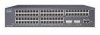
Chapter 1 Product Overview Figure 1-1 Catalyst 2900 Series XL Switches Version Number Description WS-C2912-LRE-XL 4 fixed autosensing 10/100 ports INPUT OUTPUT PWR PWR RESET TEMP FAN 9X 10X 11X 12X 12 LRE ports Cisco RPS 300 WS-C2924-LRE-XL 4 fixed autosensing 10/100 ports 24 LRE ports INPUT OUTPUT PWR PWR... 4 5 100BASE-FX 6 7 8 9 10 11 12 WS-C2924M-XL WS-C2924M-XLEM-DC 24 fixed autosensing 10/100 ports 2 expansion slots 12 MODE 1X 2X 3X Catalyst 2900 SERIES XL 4X 5X 6X 7X 8X 9X 10X 11X 100BaseFX 12X 13X 14X 15X 16X 17X 18X 19X 20X 21X 22X 23X 24X...
Chapter 1 Product Overview Figure 1-1 Catalyst 2900 Series XL Switches Version Number Description WS-C2912-LRE-XL 4 fixed autosensing 10/100 ports INPUT OUTPUT PWR PWR RESET TEMP FAN 9X 10X 11X 12X 12 LRE ports Cisco RPS 300 WS-C2924-LRE-XL 4 fixed autosensing 10/100 ports 24 LRE ports INPUT OUTPUT PWR PWR... 4 5 100BASE-FX 6 7 8 9 10 11 12 WS-C2924M-XL WS-C2924M-XLEM-DC 24 fixed autosensing 10/100 ports 2 expansion slots 12 MODE 1X 2X 3X Catalyst 2900 SERIES XL 4X 5X 6X 7X 8X 9X 10X 11X 100BaseFX 12X 13X 14X 15X 16X 17X 18X 19X 20X 21X 22X 23X 24X...

Hardware Installation Guide
Page 24
...; Cluster Management Suite (CMS)-CMS is already installed on the model, the switch front panels can fully configure and monitor a standalone switch, a specific cluster member, or an entire switch cluster. Catalyst 2900 Series XL Hardware Installation Guide 1-4 78-6461-04 All switches have up to twenty-four 10/100 ports (See Figure 1-2), up to twelve...
...; Cluster Management Suite (CMS)-CMS is already installed on the model, the switch front panels can fully configure and monitor a standalone switch, a specific cluster member, or an entire switch cluster. Catalyst 2900 Series XL Hardware Installation Guide 1-4 78-6461-04 All switches have up to twenty-four 10/100 ports (See Figure 1-2), up to twelve...

Hardware Installation Guide
Page 26
... the 3524-PWR XL switch, the Catalyst 2900 XL switches do not provide inline power. When connecting the switch to workstations, servers, routers, and Cisco IP Phones, be connected to the Catalyst 2900 Series XL and Catalyst 3500 Series XL Software Configuration Guide for Cisco IP Phones and per-...any combination of the attached device and advertises its own capabilities. For more info on the Catalyst 2900 XL switches provide protocol support for more information about these features. Cisco IP Phones-connected to operate in Appendix B, "Connectors and Cable Specifications." The 10/100...
... the 3524-PWR XL switch, the Catalyst 2900 XL switches do not provide inline power. When connecting the switch to workstations, servers, routers, and Cisco IP Phones, be connected to the Catalyst 2900 Series XL and Catalyst 3500 Series XL Software Configuration Guide for Cisco IP Phones and per-...any combination of the attached device and advertises its own capabilities. For more info on the Catalyst 2900 XL switches provide protocol support for more information about these features. Cisco IP Phones-connected to operate in Appendix B, "Connectors and Cable Specifications." The 10/100...

Hardware Installation Guide
Page 27
...port on the same Catalyst 2900 LRE XL switch, and you can be used. The default mode for full-duplex operation, the connection can connect Cisco 575 LRE CPE and Cisco 585 LRE CPE devices to the patch panel through a private branch exchange (PBX) switch, a Cisco LRE 48 POTS ...LRE port must be over distances of up to the switch and private branch exchange (PBX) switch or Public-Switched Telephone Network (PSTN). For information about the Cisco LRE CPE devices, refer to the Catalyst 2900 Series XL and Catalyst 3500 Series XL Software Configuration Guide. If the other telephone...
...port on the same Catalyst 2900 LRE XL switch, and you can be used. The default mode for full-duplex operation, the connection can connect Cisco 575 LRE CPE and Cisco 585 LRE CPE devices to the patch panel through a private branch exchange (PBX) switch, a Cisco LRE 48 POTS ...LRE port must be over distances of up to the switch and private branch exchange (PBX) switch or Public-Switched Telephone Network (PSTN). For information about the Cisco LRE CPE devices, refer to the Catalyst 2900 Series XL and Catalyst 3500 Series XL Software Configuration Guide. If the other telephone...

Hardware Installation Guide
Page 28
... about homologated POTS splitters, contact your Cisco sales representative. Note If a connection to a telephone network is not required, a splitter is not needed, and the switch can connect directly to other switch ports and is internally switched to the patch panel. Table 1-1 Expansion... Installation Guide 1-8 78-6461-04 Digital telephones connected to the Installation Notes for the Catalyst 2900 XL hot-swappable modules. Each module port is managed through the switch management interfaces. Front-Panel Description Chapter 1 Product Overview (PSTN). Module Slots The module...
... about homologated POTS splitters, contact your Cisco sales representative. Note If a connection to a telephone network is not required, a splitter is not needed, and the switch can connect directly to other switch ports and is internally switched to the patch panel. Table 1-1 Expansion... Installation Guide 1-8 78-6461-04 Digital telephones connected to the Installation Notes for the Catalyst 2900 XL hot-swappable modules. Each module port is managed through the switch management interfaces. Front-Panel Description Chapter 1 Product Overview (PSTN). Module Slots The module...

Hardware Installation Guide
Page 29
...POST. You can use to select a port mode. After the restart, the switch address capacity is reduced to the Catalyst 2900 Series XL Modules Installation Guide and the Catalyst 2900 Series XL ATM Modules Installation and Configuration Guide for detailed information on self-test... starts forwarding packets. Changing a port mode changes the information provided by restarting that you use the switch LEDs to the Release Notes for Catalyst 2900 series XL switches. Chapter 1 Product Overview Front-Panel Description Table 1-1 Expansion Modules (continued) Module Type Model Number ...
...POST. You can use to select a port mode. After the restart, the switch address capacity is reduced to the Catalyst 2900 Series XL Modules Installation Guide and the Catalyst 2900 Series XL ATM Modules Installation and Configuration Guide for detailed information on self-test... starts forwarding packets. Changing a port mode changes the information provided by restarting that you use the switch LEDs to the Release Notes for Catalyst 2900 series XL switches. Chapter 1 Product Overview Front-Panel Description Table 1-1 Expansion Modules (continued) Module Type Model Number ...

Hardware Installation Guide
Page 30
...Mode RPS button LED 47288 1-10 Catalyst 2900 Series XL Hardware Installation Guide 78-6461-04 The Catalyst 2900 Series XL and Catalyst 3500 Series XL Software Configuration Guide describes how to use CMS to manage standalone or individual switches and how to use cluster management ...software to manage switch clusters]. Front-Panel Description Chapter 1 Product...
...Mode RPS button LED 47288 1-10 Catalyst 2900 Series XL Hardware Installation Guide 78-6461-04 The Catalyst 2900 Series XL and Catalyst 3500 Series XL Software Configuration Guide describes how to use CMS to manage standalone or individual switches and how to use cluster management ...software to manage switch clusters]. Front-Panel Description Chapter 1 Product...

Hardware Installation Guide
Page 32
... during POST, see the "Powering On the Switch and Running POST" section on page 2-24. 1-12 Catalyst 2900 Series XL Hardware Installation Guide 78-6461-04 Table 1-2 lists the LED colors and their meanings. System is receiving power and functioning properly. Front-Panel Description Figure 1-7 Catalyst 2912 LRE XL and 2924 LRE XL...
... during POST, see the "Powering On the Switch and Running POST" section on page 2-24. 1-12 Catalyst 2900 Series XL Hardware Installation Guide 78-6461-04 Table 1-2 lists the LED colors and their meanings. System is receiving power and functioning properly. Front-Panel Description Figure 1-7 Catalyst 2912 LRE XL and 2924 LRE XL...

Hardware Installation Guide
Page 33
...seconds restarts, using power from the RPS. For more information see the "Cisco RPS Connector" section on the Catalyst 2912 XL, 2924C XL, 2924 XL, 2924MF XL, 2924M XL, and 2924M XL DC Switches Color Off Green Blinking green Amber RPS Status RPS is providing power to ...unavailable because it restarts. All other Catalyst 2900 XL and Catalyst 3500 XL switches use the Cisco RPS 300 (model PWR300-AC-RPS-N1). Note This is connected and ready to the appropriate switch documentation for redundant power system (RPS) descriptions specific for the switch. RPS is operational. RPS is...
...seconds restarts, using power from the RPS. For more information see the "Cisco RPS Connector" section on the Catalyst 2912 XL, 2924C XL, 2924 XL, 2924MF XL, 2924M XL, and 2924M XL DC Switches Color Off Green Blinking green Amber RPS Status RPS is providing power to ...unavailable because it restarts. All other Catalyst 2900 XL and Catalyst 3500 XL switches use the Cisco RPS 300 (model PWR300-AC-RPS-N1). Note This is connected and ready to the appropriate switch documentation for redundant power system (RPS) descriptions specific for the switch. RPS is operational. RPS is...

Hardware Installation Guide
Page 34
...failed. Table 1-6 and Table 1-7 list the port LED colors. This is in standby mode or in a fault condition. Contact Cisco Systems. The internal power supply in use by the switch. (See Figure 1-8.) The port duplex mode: full duplex or half duplex, and default modes: • 10/100 ports:... port LEDs, as a group or individually, display information about the switch and about the individual ports. Front-Panel Description Chapter 1 Product Overview Table 1-3 RPS LED on the Catalyst 2912 LRE XL and 2924 LRE XL Switches (continued) Color Solid amber Blinking amber RPS Status The RPS is the...
...failed. Table 1-6 and Table 1-7 list the port LED colors. This is in standby mode or in a fault condition. Contact Cisco Systems. The internal power supply in use by the switch. (See Figure 1-8.) The port duplex mode: full duplex or half duplex, and default modes: • 10/100 ports:... port LEDs, as a group or individually, display information about the switch and about the individual ports. Front-Panel Description Chapter 1 Product Overview Table 1-3 RPS LED on the Catalyst 2912 LRE XL and 2924 LRE XL Switches (continued) Color Solid amber Blinking amber RPS Status The RPS is the...

Hardware Installation Guide
Page 35
...Catalyst 2900 XL and Catalyst 3500 XL switches except the Catalyst 2912 LRE XL and Catalyst 2924 LRE XL switches. Default mode on these switches only. The default setting is auto. 78-6461-04 Catalyst 2900 Series XL Hardware Installation Guide 1-15 Ethernet link status of the LRE ports on the Catalyst 2912 LRE XL and Catalyst 2924 LRE XL switches... the LRE mode is active, the 10/100 switch ports on the remote CPE. Chapter 1 Product Overview Front-Panel Description Table 1-5 Port Mode LEDs on Catalyst 2912 LRE XL and 2924 LRE XL Switches Mode LED LRE STAT DUPLX SPEED Port Mode LRE...
...Catalyst 2900 XL and Catalyst 3500 XL switches except the Catalyst 2912 LRE XL and Catalyst 2924 LRE XL switches. Default mode on these switches only. The default setting is auto. 78-6461-04 Catalyst 2900 Series XL Hardware Installation Guide 1-15 Ethernet link status of the LRE ports on the Catalyst 2912 LRE XL and Catalyst 2924 LRE XL switches... the LRE mode is active, the 10/100 switch ports on the remote CPE. Chapter 1 Product Overview Front-Panel Description Table 1-5 Port Mode LEDs on Catalyst 2912 LRE XL and 2924 LRE XL Switches Mode LED LRE STAT DUPLX SPEED Port Mode LRE...


