
Hardware Installation Guide
Page 28
...splitters, contact your Cisco sales representative. Digital telephones connected to 700 kHz frequency range. Table 1-1 Expansion Modules Module Type 10/100 Ethernet 100 BASE-FX Model Number WS-X2914-XL WS-X2914-XL-V WS-X2922-XL WS-X2922-XL-V WS-X2924-XL-V Catalyst 2900 Series XL ...nature of digital PBX switches, some digital PBX switch services use the 0 to digital PBX switches that the module slots support. Each module port is internally switched to the Installation Notes for the Catalyst 2900 XL hot-swappable modules. For more information about the Cisco LRE 48 POTS Splitter ...
...splitters, contact your Cisco sales representative. Digital telephones connected to 700 kHz frequency range. Table 1-1 Expansion Modules Module Type 10/100 Ethernet 100 BASE-FX Model Number WS-X2914-XL WS-X2914-XL-V WS-X2922-XL WS-X2922-XL-V WS-X2924-XL-V Catalyst 2900 Series XL ...nature of digital PBX switches, some digital PBX switch services use the 0 to digital PBX switches that the module slots support. Each module port is internally switched to the Installation Notes for the Catalyst 2900 XL hot-swappable modules. For more information about the Cisco LRE 48 POTS Splitter ...
Hardware Installation Guide
Page 65
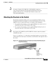
... screws to attach each bracket, according to these brackets, contact your Cisco sales representative. Chapter 2 Installation Installing the Switch on a Wall Note To mount a Catalyst 2912 LRE XL or 2924 LRE XL switch on a wall, you need to obtain two special wall-mount brackets (Cisco part number wallmount-1ru=.) To order these guidelines: • For parallel...
... screws to attach each bracket, according to these brackets, contact your Cisco sales representative. Chapter 2 Installation Installing the Switch on a Wall Note To mount a Catalyst 2912 LRE XL or 2924 LRE XL switch on a wall, you need to obtain two special wall-mount brackets (Cisco part number wallmount-1ru=.) To order these guidelines: • For parallel...
Hardware Installation Guide
Page 83
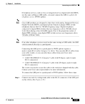
... telephone services travel on the switch. (See Figure 2-30.) 78-6461-04 Catalyst 2900 Series XL Hardware Installation Guide 2-39 Connecting the LRE port to a patch panel or POTS splitter requires a male-to a patch panel or POTS splitter, follow these cables from your Cisco sales representative for more information. Note Cisco LRE products are shipped...
... telephone services travel on the switch. (See Figure 2-30.) 78-6461-04 Catalyst 2900 Series XL Hardware Installation Guide 2-39 Connecting the LRE port to a patch panel or POTS splitter requires a male-to a patch panel or POTS splitter, follow these cables from your Cisco sales representative for more information. Note Cisco LRE products are shipped...
Hardware Installation Guide
Page 85
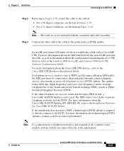
... management of CPE devices, refer to the Catalyst 2900 Series XL and Catalyst 3500 Series XL Software Configuration Guide. For more information about the LRE link between the switch LRE port and the CPE, as well as information about the Cisco LRE 48 POTS Splitter (PS-1M-LRE-...LRE data (high-frequency) and voice (low-frequency) traffic from the telephone line to the Cisco LRE CPE Hardware Installation Guide. For more information about homologated POTS splitters, contact your Cisco sales representative. Each LRE port status LED turns on when it establishes a link with the connector and...
... management of CPE devices, refer to the Catalyst 2900 Series XL and Catalyst 3500 Series XL Software Configuration Guide. For more information about the LRE link between the switch LRE port and the CPE, as well as information about the Cisco LRE 48 POTS Splitter (PS-1M-LRE-...LRE data (high-frequency) and voice (low-frequency) traffic from the telephone line to the Cisco LRE CPE Hardware Installation Guide. For more information about homologated POTS splitters, contact your Cisco sales representative. Each LRE port status LED turns on when it establishes a link with the connector and...
Hardware Installation Guide
Page 95
... the effect of stubs or bridge taps by the switch. • Change to establish an LRE link with the profile selected by terminating them with other services. • Restrict the use of spectrally incompatible services. Consult Cisco sales representative for installation optimization. 78-6461-04 Catalyst 2900 Series XL Hardware Installation Guide 3-7 Chapter 3 Troubleshooting...
... the effect of stubs or bridge taps by the switch. • Change to establish an LRE link with the profile selected by terminating them with other services. • Restrict the use of spectrally incompatible services. Consult Cisco sales representative for installation optimization. 78-6461-04 Catalyst 2900 Series XL Hardware Installation Guide 3-7 Chapter 3 Troubleshooting...

Hardware Installation Guide
Page 96
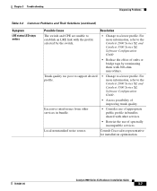
Resolution • Connect telephone cable into PHONE socket on LRE line. Unfiltered telephone tap on LRE CPE device. • Terminate additional telephone lines with microfilters. Catalyst 2900 Series XL Hardware Installation Guide 3-8 78-6461-04 For more information about microfilters, contact your Cisco sales representative. Diagnosing Problems Chapter 3 Troubleshooting Table 3-2 Common Problems and Their Solutions (continued) Symptom Possible Cause LRE link goes down when telephone is taken off-hook, placed on-hook, rings, or dials.
Resolution • Connect telephone cable into PHONE socket on LRE line. Unfiltered telephone tap on LRE CPE device. • Terminate additional telephone lines with microfilters. Catalyst 2900 Series XL Hardware Installation Guide 3-8 78-6461-04 For more information about microfilters, contact your Cisco sales representative. Diagnosing Problems Chapter 3 Troubleshooting Table 3-2 Common Problems and Their Solutions (continued) Symptom Possible Cause LRE link goes down when telephone is taken off-hook, placed on-hook, rings, or dials.