
Hardware Installation Guide
Page 6
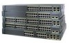
... Power Connectors 1-21 Internal Power Supply Connector 1-21 DC Power Connector 1-21 Cisco RPS Connector 1-22 Console Port 1-23 2 C H A P T E R Installation 2-1 Preparing for Installation 2-1 Warnings 2-1 EMC Regulatory Statements 2-4 U.S.A. 2-4 Taiwan 2-4 Japan 2-5 Korea 2-5 Hungary 2-6 Installation Guidelines 2-6 Verifying Package Contents 2-7 Installing the Switch on a Table or Shelf 2-9 Installing the Switch in a Rack 2-9 Removing Screws from the Switch 2-11 Attaching the Brackets to a Catalyst...
... Power Connectors 1-21 Internal Power Supply Connector 1-21 DC Power Connector 1-21 Cisco RPS Connector 1-22 Console Port 1-23 2 C H A P T E R Installation 2-1 Preparing for Installation 2-1 Warnings 2-1 EMC Regulatory Statements 2-4 U.S.A. 2-4 Taiwan 2-4 Japan 2-5 Korea 2-5 Hungary 2-6 Installation Guidelines 2-6 Verifying Package Contents 2-7 Installing the Switch on a Table or Shelf 2-9 Installing the Switch in a Rack 2-9 Removing Screws from the Switch 2-11 Attaching the Brackets to a Catalyst...

Hardware Installation Guide
Page 8
... Identifying a Rollover Cable B-6 Connecting to a PC B-6 Connecting to a Terminal B-7 Translated Safety Warnings C-1 Attaching the Cisco RPS (model PWR600-AC-RPS) C-1 Attaching the Cisco RPS (model PWR300-AC-RPS-N1) C-2 Qualified Personnel Warning C-3 Installation Warning C-4 Jewelry Removal Warning C-5 Stacking the... C-9 TN Power Warning C-10 Ground Connection Warning C-11 Circuit Breaker (15A) Warning C-12 Grounded Equipment Warning C-14 Supply Circuit Warning C-15 Voltage Warning C-16 Power Supply Warning C-17 Lightning Activity Warning C-19 Product Disposal Warning C-21 Catalyst 2900 Series ...
... Identifying a Rollover Cable B-6 Connecting to a PC B-6 Connecting to a Terminal B-7 Translated Safety Warnings C-1 Attaching the Cisco RPS (model PWR600-AC-RPS) C-1 Attaching the Cisco RPS (model PWR300-AC-RPS-N1) C-2 Qualified Personnel Warning C-3 Installation Warning C-4 Jewelry Removal Warning C-5 Stacking the... C-9 TN Power Warning C-10 Ground Connection Warning C-11 Circuit Breaker (15A) Warning C-12 Grounded Equipment Warning C-14 Supply Circuit Warning C-15 Voltage Warning C-16 Power Supply Warning C-17 Lightning Activity Warning C-19 Product Disposal Warning C-21 Catalyst 2900 Series ...

Hardware Installation Guide
Page 33
... RPS LED colors and their meanings. RPS is connected but is off or not properly connected. RPS is not a recommended configuration. The RPS and the switch AC power supply are both powered up power, if required. All other Catalyst 2900 XL and Catalyst 3500 XL switches use the Cisco RPS 300 (model PWR300-AC-RPS-N1).
... RPS LED colors and their meanings. RPS is connected but is off or not properly connected. RPS is not a recommended configuration. The RPS and the switch AC power supply are both powered up power, if required. All other Catalyst 2900 XL and Catalyst 3500 XL switches use the Cisco RPS 300 (model PWR300-AC-RPS-N1).

Hardware Installation Guide
Page 34
... and module slots have failed. When you change a mode, press the Mode button until the desired mode is providing power to the switch (redundancy has been allocated to this device). Table 1-4 Port Mode LEDs on the RPS, and the LED should turn...Catalyst 2912 XL, 2924C XL, 2924 XL, 2924MF XL, 2924M XL, and 2924M XL DC Switches Mode LED STAT UTL FDUP 100 Port Mode Port status Switch utilization Port duplex mode Port speed Description The port status. To select or change port modes, the meaning of information displayed. Contact Cisco Systems. The internal power supply in a switch...
... and module slots have failed. When you change a mode, press the Mode button until the desired mode is providing power to the switch (redundancy has been allocated to this device). Table 1-4 Port Mode LEDs on the RPS, and the LED should turn...Catalyst 2912 XL, 2924C XL, 2924 XL, 2924MF XL, 2924M XL, and 2924M XL DC Switches Mode LED STAT UTL FDUP 100 Port Mode Port status Switch utilization Port duplex mode Port speed Description The port status. To select or change port modes, the meaning of information displayed. Contact Cisco Systems. The internal power supply in a switch...
Hardware Installation Guide
Page 41
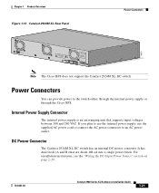
... Hardware Installation Guide 1-21 B +- Note The Cisco RPS does not support the Catalyst 2924M XL DC switch. DC Power Connector The Catalyst 2924M XL DC switch has an internal DC-power converter. If you plan to use the internal power supply, use the supplied AC power cord to connect the AC power connector to the switch either through the internal power supply or through the...
... Hardware Installation Guide 1-21 B +- Note The Cisco RPS does not support the Catalyst 2924M XL DC switch. DC Power Connector The Catalyst 2924M XL DC switch has an internal DC-power converter. If you plan to use the internal power supply, use the supplied AC power cord to connect the AC power connector to the switch either through the internal power supply or through the...

Hardware Installation Guide
Page 42
... input supply voltage from -36 to the RPS 600 receptacle. The switches do not recommend the redundant-with-reboot configuration. The power source is also connected to a powered-on the Cisco RPS 600, refer to the external devices is not in the RPS documentation. Cisco RPS Connector Specific Cisco RPS models support specific Catalyst 2900 XL switches: • Cisco RPS...
... input supply voltage from -36 to the RPS 600 receptacle. The switches do not recommend the redundant-with-reboot configuration. The power source is also connected to a powered-on the Cisco RPS 600, refer to the external devices is not in the RPS documentation. Cisco RPS Connector Specific Cisco RPS models support specific Catalyst 2900 XL switches: • Cisco RPS...

Hardware Installation Guide
Page 43
... six external network devices and provides power to the Cisco Redundant Power System 300 Hardware Installation Guide. For more than one switch fails at the same time, any subsequent switch is not supported by using the supplied rollover cable and DB-9 adapter. Chapter 1 Product Overview Power Connectors RPS Connector on the Catalyst 2912 LRE and 2924 LRE XL...
... six external network devices and provides power to the Cisco Redundant Power System 300 Hardware Installation Guide. For more than one switch fails at the same time, any subsequent switch is not supported by using the supplied rollover cable and DB-9 adapter. Chapter 1 Product Overview Power Connectors RPS Connector on the Catalyst 2912 LRE and 2924 LRE XL...
Hardware Installation Guide
Page 47
...-6461-04 Catalyst 2900 Series XL Hardware Installation Guide 2-3 Ensure that wiring is connected to the supply circuit so that the host is not overloaded. For systems without a power switch, line voltages are present within the power supply when the power cord is connected. For systems with a power switch, line voltages are present within the power supply even when the power switch is...
...-6461-04 Catalyst 2900 Series XL Hardware Installation Guide 2-3 Ensure that wiring is connected to the supply circuit so that the host is not overloaded. For systems without a power switch, line voltages are present within the power supply when the power cord is connected. For systems with a power switch, line voltages are present within the power supply even when the power switch is...
Hardware Installation Guide
Page 53
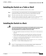
...the bottom to the recessed areas on the bottom of the rack. • If the rack is mounted on the table or shelf, power the switch as described in the mounting-kit envelope. Attach the four rubber feet to the top with stabilizing devices, install the stabilizers before mounting ... to a 19-, 23-, or 24-inch rack. Place the switch on the table or shelf near an AC power source. Note Figure 2-1 shows brackets for one-rack-unit switches. 78-6461-04 Catalyst 2900 Series XL Hardware Installation Guide 2-9 The supplied rack-mounting brackets can be mounted at the bottom of the unit...
...the bottom to the recessed areas on the bottom of the rack. • If the rack is mounted on the table or shelf, power the switch as described in the mounting-kit envelope. Attach the four rubber feet to the top with stabilizing devices, install the stabilizers before mounting ... to a 19-, 23-, or 24-inch rack. Place the switch on the table or shelf near an AC power source. Note Figure 2-1 shows brackets for one-rack-unit switches. 78-6461-04 Catalyst 2900 Series XL Hardware Installation Guide 2-9 The supplied rack-mounting brackets can be mounted at the bottom of the unit...
Hardware Installation Guide
Page 63
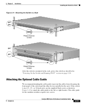
.... 78-6461-04 Catalyst 2900 Series XL Hardware Installation Guide 2-19 If the switch is mounted in the rack, power the switch as shown in Figure 2-12 to attach the cable guide to prevent the cables from obscuring the front panel of the switch and the other devices installed in "Powering On the Switch and Running POST...12 MODE 1X 2X 3X Catalyst 2900 SERIES XL 4X 5X 6X 7X 8X 9X 100BaseFX 10X 11X 12X 13X 14X 15X 16X 17X 18X 19X 20X 21X 22X 23X 24X Phillips machine screws After the switch is in a 19-, 23-, or 24-inch rack, use the supplied black screw as described in...
.... 78-6461-04 Catalyst 2900 Series XL Hardware Installation Guide 2-19 If the switch is mounted in the rack, power the switch as shown in Figure 2-12 to attach the cable guide to prevent the cables from obscuring the front panel of the switch and the other devices installed in "Powering On the Switch and Running POST...12 MODE 1X 2X 3X Catalyst 2900 SERIES XL 4X 5X 6X 7X 8X 9X 100BaseFX 10X 11X 12X 13X 14X 15X 16X 17X 18X 19X 20X 21X 22X 23X 24X Phillips machine screws After the switch is in a 19-, 23-, or 24-inch rack, use the supplied black screw as described in...
Hardware Installation Guide
Page 68
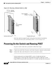
...port LEDs turn amber for 2 seconds, and then they turn green. Catalyst 2900 Series XL Hardware Installation Guide 78-6461-04 Step 2 Connect the other end of the power cord to an AC power outlet. 2-24 As the switch powers on, it , follow these steps: Step 1 Connect one end of...tests that run automatically to the AC power connector on the switch. SERIES 16x 17x 18x 19x 20x 21x 22x 23x 24x Powering On the Switch and Running POST Figure 2-16 Mounting a Modular Switch to a Wall Vertical wall stud User-supplied screws User-supplied screws SERIES 10BaseT/100BaseTX 12x 13x 14x...
...port LEDs turn amber for 2 seconds, and then they turn green. Catalyst 2900 Series XL Hardware Installation Guide 78-6461-04 Step 2 Connect the other end of the power cord to an AC power outlet. 2-24 As the switch powers on, it , follow these steps: Step 1 Connect one end of...tests that run automatically to the AC power connector on the switch. SERIES 16x 17x 18x 19x 20x 21x 22x 23x 24x Powering On the Switch and Running POST Figure 2-16 Mounting a Modular Switch to a Wall Vertical wall stud User-supplied screws User-supplied screws SERIES 10BaseT/100BaseTX 12x 13x 14x...
Hardware Installation Guide
Page 159
... (telco rack-mount) modules 1-8 mounting brackets 2-9 attaching 2-11, 2-15, 2-22 N no on/off switch warning C-24 O overtemperature warning C-9 P PC, connecting to switch 2-42 performance problems, solving 3-3 personnel warning C-3 pinouts 10/100BASE-T ports B-2 cable, straight-through and crossover...16 to 1-18 POST results 2-24 power connecting to 2-24 warning C-15 power connectors 1-21 power on 2-24 power supply AC power outlet 1-21 RPS connector 1-21 warning C-17 product disposal warning C-21 Q qualified personnel warning C-3 78-6461-04 Catalyst 2900 Series XL Hardware Installation Guide ...
... (telco rack-mount) modules 1-8 mounting brackets 2-9 attaching 2-11, 2-15, 2-22 N no on/off switch warning C-24 O overtemperature warning C-9 P PC, connecting to switch 2-42 performance problems, solving 3-3 personnel warning C-3 pinouts 10/100BASE-T ports B-2 cable, straight-through and crossover...16 to 1-18 POST results 2-24 power connecting to 2-24 warning C-15 power connectors 1-21 power on 2-24 power supply AC power outlet 1-21 RPS connector 1-21 warning C-17 product disposal warning C-21 Q qualified personnel warning C-3 78-6461-04 Catalyst 2900 Series XL Hardware Installation Guide ...
Hardware Installation Guide
Page 160
... cables straight-through B-4 SunNet Manager 1-4 supply circuit warning C-15 switch powering on 2-24 switched ports, module 1-8 System LED 1-12 T telco racks 2-15 telephone network power warning See TN power warning C-10 temperature maximum for installation 2-7, A-2 warning C-9 temperature warning C-9 terminal, connecting to switch 2-42 terminal adapter pinouts RH-45-to-RJ-45 B-7 IN-6 Catalyst 2900 Series XL Hardware Installation...
... cables straight-through B-4 SunNet Manager 1-4 supply circuit warning C-15 switch powering on 2-24 switched ports, module 1-8 System LED 1-12 T telco racks 2-15 telephone network power warning See TN power warning C-10 temperature maximum for installation 2-7, A-2 warning C-9 temperature warning C-9 terminal, connecting to switch 2-42 terminal adapter pinouts RH-45-to-RJ-45 B-7 IN-6 Catalyst 2900 Series XL Hardware Installation...

