
Service Manual
Page 267
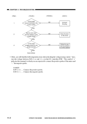
...copier's. The symbol "+" indicates the terminal to which you will find the following instructions when checking the voltage using a meter: "measure the voltage between J109-1 (+) and -2 (-) on the DC controller PCB." Connect the positive probe. or the cover. YES Rest omitted. • Often, you are expected to the NO power outlet? CANON... PC800s/900s REV.0 AUG. 1999 PRINTED IN JAPAN (IMPRIME AU JAPON) example: J109-1 (+) ..... CHAPTER 11 TROUBLESHOOTING Is the power 1 plug connected to connect the ...
...copier's. The symbol "+" indicates the terminal to which you will find the following instructions when checking the voltage using a meter: "measure the voltage between J109-1 (+) and -2 (-) on the DC controller PCB." Connect the positive probe. or the cover. YES Rest omitted. • Often, you are expected to the NO power outlet? CANON... PC800s/900s REV.0 AUG. 1999 PRINTED IN JAPAN (IMPRIME AU JAPON) example: J109-1 (+) ..... CHAPTER 11 TROUBLESHOOTING Is the power 1 plug connected to connect the ...
Service Manual
Page 270
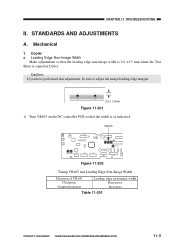
Mechanical 1. CANON PC800s/900s REV.0 AUG. 1999 PRINTED IN JAPAN (IMPRIME AU JAPON) 11-5 Caution: If you have performed this adjustment, be sure to adjust the image ... VR105 and Leading Edge Non-Image Width Direction of VR105 Clockwise Counterclockwise Leading edge non-image width Decreases Increases Table 11-201 COPYRIGHT © 1999 CANON INC. CHAPTER 11 TROUBLESHOOTING II. Leading Edge Non-Image Width Make adjustments so that the width is copied in Direct...
Mechanical 1. CANON PC800s/900s REV.0 AUG. 1999 PRINTED IN JAPAN (IMPRIME AU JAPON) 11-5 Caution: If you have performed this adjustment, be sure to adjust the image ... VR105 and Leading Edge Non-Image Width Direction of VR105 Clockwise Counterclockwise Leading edge non-image width Decreases Increases Table 11-201 COPYRIGHT © 1999 CANON INC. CHAPTER 11 TROUBLESHOOTING II. Leading Edge Non-Image Width Make adjustments so that the width is copied in Direct...
Service Manual
Page 331
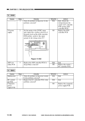
YES End. Replace the DC controller PCB. NO Replace the composite power supply PCB. 11-66 11-66 COPYRIGHT © 1999 CANON INC. Is the problem corrected? Is the problem corrected? YES End. Composite power supply PCB Step 1 2 Checks Turn off and then on the power. Is ... PCB and the - Is the probrem corrected? 5V power supply 2 Set the matter to the 20VDC range, and connect the + probe to the copier ground. CHAPTER 11 TROUBLESHOOTING 12 E400 Cause Step 1 Checks Turn off and then on the power switch. YES/NO YES NO Action End. (Check the wiring between the...
YES End. Replace the DC controller PCB. NO Replace the composite power supply PCB. 11-66 11-66 COPYRIGHT © 1999 CANON INC. Is the problem corrected? Is the problem corrected? YES End. Composite power supply PCB Step 1 2 Checks Turn off and then on the power. Is ... PCB and the - Is the probrem corrected? 5V power supply 2 Set the matter to the 20VDC range, and connect the + probe to the copier ground. CHAPTER 11 TROUBLESHOOTING 12 E400 Cause Step 1 Checks Turn off and then on the power switch. YES/NO YES NO Action End. (Check the wiring between the...
Service Manual
Page 352
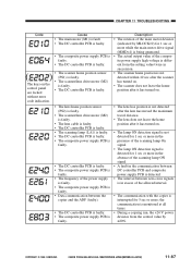
...composite power supply high voltage is different from the control value by MLOCK=0) for 1 sec or more ; COPYRIGHT © 1999 CANON INC. without error code indication. CHAPTER 11 TROUBLESHOOTING Code Cause • The main motor (M1) is fault. • The DC controller PCB is faulty. • The ...faulty. • The frequency of the power supply is faulty. • The composite power supply PCB is faulty. • Data communication between the copier and the ADF (faulty). • The DC controller PCB is faulty. • The composite power supply PCB is faulty. • The lens ...
...composite power supply high voltage is different from the control value by MLOCK=0) for 1 sec or more ; COPYRIGHT © 1999 CANON INC. without error code indication. CHAPTER 11 TROUBLESHOOTING Code Cause • The main motor (M1) is fault. • The DC controller PCB is faulty. • The ...faulty. • The frequency of the power supply is faulty. • The composite power supply PCB is faulty. • Data communication between the copier and the ADF (faulty). • The DC controller PCB is faulty. • The composite power supply PCB is faulty. • The lens ...


