
Service Manual
Page 38
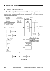
...Transfer charging roller • Static eliminator AE sensor PCB Thermistor • Scanner thermistor • Fixing thermistor Control panel Main motor Main driver PCB motor Solenoid • Pickup clutch solenoid • Registration clutch solenoid • Lens solenoid • Multifeeder pickup solenoid •...switch Scanner/ lens drive motor Scanner cooling fan Sensor/ switch ADF ADF load Figure 2-102 2-2 COPYRIGHT © 1999 CANON INC. Outline of Electrical Circuitry The machine's major electric mechanisms are controlled by the microprocessor mounted on the DC controller ...
...Transfer charging roller • Static eliminator AE sensor PCB Thermistor • Scanner thermistor • Fixing thermistor Control panel Main motor Main driver PCB motor Solenoid • Pickup clutch solenoid • Registration clutch solenoid • Lens solenoid • Multifeeder pickup solenoid •...switch Scanner/ lens drive motor Scanner cooling fan Sensor/ switch ADF ADF load Figure 2-102 2-2 COPYRIGHT © 1999 CANON INC. Outline of Electrical Circuitry The machine's major electric mechanisms are controlled by the microprocessor mounted on the DC controller ...
Service Manual
Page 42
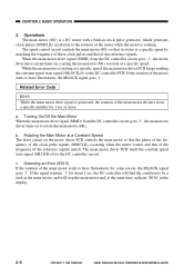
...of the clock pulse signals (MMCLK) occurring when the motor rotates and that of the frequency of the reference signals match. The main motor driver PCB sends the constant speed state signal (MLOCK=0) to the DC controller PCB. The speed control circuit controls the main motor (M1) ... a DC motor with a built-in clock pulse generator, which generates clock pulses (MMCLK) in relation to have fluctuations, the MLOCK signal goes '1'. a. CANON PC800s/900s REV.0 AUG. 1999 PRINTED IN JAPAN (IMPRIME AU JAPON) Rotating the Main Motor at a Constant Speed The drive circuit on to have fluctuations...
...of the clock pulse signals (MMCLK) occurring when the motor rotates and that of the frequency of the reference signals match. The main motor driver PCB sends the constant speed state signal (MLOCK=0) to the DC controller PCB. The speed control circuit controls the main motor (M1) ... a DC motor with a built-in clock pulse generator, which generates clock pulses (MMCLK) in relation to have fluctuations, the MLOCK signal goes '1'. a. CANON PC800s/900s REV.0 AUG. 1999 PRINTED IN JAPAN (IMPRIME AU JAPON) Rotating the Main Motor at a Constant Speed The drive circuit on to have fluctuations...
Service Manual
Page 45
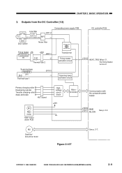
... 3. Primary charging roller Developing cylinder Transfer charging roller Static eliminator HVT board M1 Main motor Main motor driver PCB Highvoltage circuit block +24V Microprocessor Communication with the composite power supply J103-6 MMD J104-1 MLOCK See p. 2-5. CANON PC800s/900s REV.0 AUG. 1999 PRINTED IN JAPAN (IMPRIME AU JAPON) 2-9 Outputs from the DC Controller... activation circuit Scanning lamp activation circuit J104-2 HEAT_TRG When '0', the fixing heater turns on. M2 Scanner/ lens drive motor Figure 2-107 See p. 3-7. COPYRIGHT © 1999 CANON INC.
... 3. Primary charging roller Developing cylinder Transfer charging roller Static eliminator HVT board M1 Main motor Main motor driver PCB Highvoltage circuit block +24V Microprocessor Communication with the composite power supply J103-6 MMD J104-1 MLOCK See p. 2-5. CANON PC800s/900s REV.0 AUG. 1999 PRINTED IN JAPAN (IMPRIME AU JAPON) 2-9 Outputs from the DC Controller... activation circuit Scanning lamp activation circuit J104-2 HEAT_TRG When '0', the fixing heater turns on. M2 Scanner/ lens drive motor Figure 2-107 See p. 3-7. COPYRIGHT © 1999 CANON INC.

Service Manual
Page 54
... forward or in Direct). Outline The scanner is moved varies according to the length of rotation changes to the selected reproduction ratio on a continuous basis; CANON PC800s/900s REV.0 AUG. 1999 PRINTED IN JAPAN (IMPRIME AU JAPON) M2 SC_COM SC_B* SC_B SC_COM SC_A* SC_A PS1 Light-blocking plate Scanner home position...
... forward or in Direct). Outline The scanner is moved varies according to the length of rotation changes to the selected reproduction ratio on a continuous basis; CANON PC800s/900s REV.0 AUG. 1999 PRINTED IN JAPAN (IMPRIME AU JAPON) M2 SC_COM SC_B* SC_B SC_COM SC_A* SC_A PS1 Light-blocking plate Scanner home position...
Service Manual
Page 57
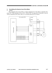
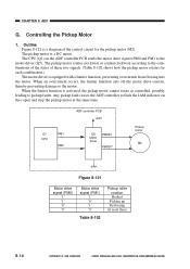
CHAPTER 3 EXPOSURE SYSTEM 5. CANON PC800s/900s REV.0 AUG. 1999 PRINTED IN JAPAN (IMPRIME AU JAPON) 3-7 The timing at which the drive power (SC-COM) and pulses (SC-A, SCA*, SC-B, ... its rotation. (Q101) DC controller PCB +24VU R399 J110 SC-COM SC-COM Microprocessor A A* B B* Current switching signal 1 Current switching signal 2 Current switching signal 3 (Q109) Motor driver circuit SC-A SC-A* SC-B SC-B* M2 COPYRIGHT © 1999...
CHAPTER 3 EXPOSURE SYSTEM 5. CANON PC800s/900s REV.0 AUG. 1999 PRINTED IN JAPAN (IMPRIME AU JAPON) 3-7 The timing at which the drive power (SC-COM) and pulses (SC-A, SCA*, SC-B, ... its rotation. (Q101) DC controller PCB +24VU R399 J110 SC-COM SC-COM Microprocessor A A* B B* Current switching signal 1 Current switching signal 2 Current switching signal 3 (Q109) Motor driver circuit SC-A SC-A* SC-B SC-B* M2 COPYRIGHT © 1999...
Service Manual
Page 58
... motor for some reason, the fuse (R339) on the DC controller PCB receives instructions from 1 to 3 generated by the microprocessor (Q101). CANON PC800s/900s REV.0 AUG. 1999 PRINTED IN JAPAN (IMPRIME AU JAPON) CHAPTER 3 EXPOSURE SYSTEM b. Operations The microprocessor (Q101) mounted on the...applies drive pulses to the sequence and frequency of its rotation according to the scanner/lens drive motor (M2) through the motor driver circuit. The current switching signals from the control panel PCB copying mode settings (e.g., reproduction ratio). The motor drive voltage is switched...
... motor for some reason, the fuse (R339) on the DC controller PCB receives instructions from 1 to 3 generated by the microprocessor (Q101). CANON PC800s/900s REV.0 AUG. 1999 PRINTED IN JAPAN (IMPRIME AU JAPON) CHAPTER 3 EXPOSURE SYSTEM b. Operations The microprocessor (Q101) mounted on the...applies drive pulses to the sequence and frequency of its rotation according to the scanner/lens drive motor (M2) through the motor driver circuit. The current switching signals from the control panel PCB copying mode settings (e.g., reproduction ratio). The motor drive voltage is switched...
Service Manual
Page 183
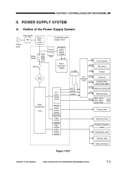
CANON PC800s/900s REV.0 AUG. 1999 PRINTED IN JAPAN (IMPRIME AU JAPON) 7-3 Outline of the Power Supply System Door switch DS1 Power plug Noise filter circuit ... +24VR DC +24VU controller PCB +24VU Solenoid Scanner/lens drive motor (M2) +24VU Scanner cooling fan +24VU Blanking lamp +24VU Main motor/ main motor M1 driver PCB Fixing heater Scanning lamp Primary charging roller Developing roller Transfer roller Static eliminator Figure 7-201 COPYRIGHT © 1999...
CANON PC800s/900s REV.0 AUG. 1999 PRINTED IN JAPAN (IMPRIME AU JAPON) 7-3 Outline of the Power Supply System Door switch DS1 Power plug Noise filter circuit ... +24VR DC +24VU controller PCB +24VU Solenoid Scanner/lens drive motor (M2) +24VU Scanner cooling fan +24VU Blanking lamp +24VU Main motor/ main motor M1 driver PCB Fixing heater Scanning lamp Primary charging roller Developing roller Transfer roller Static eliminator Figure 7-201 COPYRIGHT © 1999...
Service Manual
Page 220
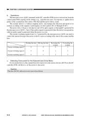
...thereby preventing damage to flash the JAM indicator on the ADF controller PCB sends the motor drive signals PM0 and PM1 to the motor driver (Q5). CANON PC800s/900s REV.0 AUG. 1999 PRINTED IN JAPAN (IMPRIME AU JAPON) Controlling the Pickup Motor 1. The pickup motor is a diagram...) '1' '1' '0' '0' Motor drive signal (PM1) '1' '0' '1' '0' Table 8-102 Pickup roller rotation Braked Picking up Delivering At reset (free) 8-14 COPYRIGHT © 1999 CANON INC. CHAPTER 8 ADF G. Outline Figure 8-121 is a DC motor. The CPU (Q1) on the copier and stop the pickup motor at the same time.
...thereby preventing damage to flash the JAM indicator on the ADF controller PCB sends the motor drive signals PM0 and PM1 to the motor driver (Q5). CANON PC800s/900s REV.0 AUG. 1999 PRINTED IN JAPAN (IMPRIME AU JAPON) Controlling the Pickup Motor 1. The pickup motor is a diagram...) '1' '1' '0' '0' Motor drive signal (PM1) '1' '0' '1' '0' Table 8-102 Pickup roller rotation Braked Picking up Delivering At reset (free) 8-14 COPYRIGHT © 1999 CANON INC. CHAPTER 8 ADF G. Outline Figure 8-121 is a DC motor. The CPU (Q1) on the copier and stop the pickup motor at the same time.
Service Manual
Page 221
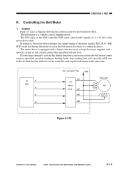
... motor cannot rotate as specified, possibly leading to the motor driver (Q4). Q1 A CPU A* B B* ADF controller PCB +24V MA Q4 Motor driver MA* MB MB* Belt motor M1 Figure 8-122 COPYRIGHT © 1999 CANON INC. In response, the motor driver changes the output timing of the pulse signals (MA, MA...*, MB, MB*) used for the belt motor (M2). The motor driver is equipped with a specific current so that current greater than ...
... motor cannot rotate as specified, possibly leading to the motor driver (Q4). Q1 A CPU A* B B* ADF controller PCB +24V MA Q4 Motor driver MA* MB MB* Belt motor M1 Figure 8-122 COPYRIGHT © 1999 CANON INC. In response, the motor driver changes the output timing of the pulse signals (MA, MA...*, MB, MB*) used for the belt motor (M2). The motor driver is equipped with a specific current so that current greater than ...
Service Manual
Page 328
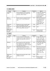
... NO YES Action Correct the connection of J102 on the fixing heater side? Replace the main motor (M1). Check the wiring from the main motor driver PCB to the fixing heater; End. Is the problem corrected? 4 Replace the composite power supply PCB. NO Replace the DC controller PCB. 5 E010 Cause ...PCB about 24 V? if normal, see "DC power fails to turn on the composite power supply PCB and the wiring to the thermistor (TH1) normal? CANON PC800s/900s REV.0 AUG. 1999 PRINTED IN JAPAN (IMPRIME AU JAPON) 11-63 Is the wiring from the composite power supply PCB to the composite...
... NO YES Action Correct the connection of J102 on the fixing heater side? Replace the main motor (M1). Check the wiring from the main motor driver PCB to the fixing heater; End. Is the problem corrected? 4 Replace the composite power supply PCB. NO Replace the DC controller PCB. 5 E010 Cause ...PCB about 24 V? if normal, see "DC power fails to turn on the composite power supply PCB and the wiring to the thermistor (TH1) normal? CANON PC800s/900s REV.0 AUG. 1999 PRINTED IN JAPAN (IMPRIME AU JAPON) 11-63 Is the wiring from the composite power supply PCB to the composite...
Service Manual
Page 333
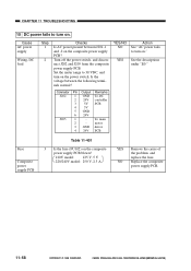
...5 GND 6 24V J205 1 - Fuse Composite power supply PCB Table 11-401 3 Is the fuse (FU102) on ." Set the meter range to turn on. To main 2 - CANON PC800s/900s REV.0 AUG. 1999 PRINTED IN JAPAN (IMPRIME AU JAPON) NO Replace the composite power supply PCB. 11-68 11-68 COPYRIGHT © 1999... VDC, and turn on the power switch. Turn off the power switch, and disconnect J202 and J205 from the composite power supply PCB. motor 3 GND driver 4 24V PCB Action See "AC power fails to turn on the composite power supply PCB blown? 120V model: 125 V, 5 V 220/240V model: 250 V, 2.5 A YES ...
...5 GND 6 24V J205 1 - Fuse Composite power supply PCB Table 11-401 3 Is the fuse (FU102) on ." Set the meter range to turn on. To main 2 - CANON PC800s/900s REV.0 AUG. 1999 PRINTED IN JAPAN (IMPRIME AU JAPON) NO Replace the composite power supply PCB. 11-68 11-68 COPYRIGHT © 1999... VDC, and turn on the power switch. Turn off the power switch, and disconnect J202 and J205 from the composite power supply PCB. motor 3 GND driver 4 24V PCB Action See "AC power fails to turn on the composite power supply PCB blown? 120V model: 125 V, 5 V 220/240V model: 250 V, 2.5 A YES ...
Service Manual
Page 360
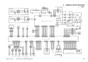
...position sensor paper sensor (Single-feeder type only) SL5 Cassette pickup solenoid PS4 Vertical path roller paper sensor COPYRIGHT © 1999 CANON INC. [220/240V] H N Line filter J502 J501 FT2 FT4 LF1 2 2 FT1 FT3 1 1 J1 DS1 Door ... FU1 Scanning lamp LA1 J17 FT6 FT5 Fixing heater H1 J16 1 2 J15 J2 FU2 Thermal fuse 2 J434 11 22 C. CANON PC800s/900s REV.0 AUG. 1999 PRINTED IN JAPAN (IMPRIME AU JAPON) J751 3 2 1 Q751 Pre-registration roller paper sensor... J4 Fixing film Varistor 1 1 2 J303 Power switch A-5 GENERAL CIRCUIT DIAGRAM MAIN MOTOR DRIVER PCB 1.
...position sensor paper sensor (Single-feeder type only) SL5 Cassette pickup solenoid PS4 Vertical path roller paper sensor COPYRIGHT © 1999 CANON INC. [220/240V] H N Line filter J502 J501 FT2 FT4 LF1 2 2 FT1 FT3 1 1 J1 DS1 Door ... FU1 Scanning lamp LA1 J17 FT6 FT5 Fixing heater H1 J16 1 2 J15 J2 FU2 Thermal fuse 2 J434 11 22 C. CANON PC800s/900s REV.0 AUG. 1999 PRINTED IN JAPAN (IMPRIME AU JAPON) J751 3 2 1 Q751 Pre-registration roller paper sensor... J4 Fixing film Varistor 1 1 2 J303 Power switch A-5 GENERAL CIRCUIT DIAGRAM MAIN MOTOR DRIVER PCB 1.