
Service Manual
Page 3
...Maintenance and Servicing provides tables of maintenance/inspection, standards/ adjustments, and problem identification (image fault/malfunction). Chapter 11 Troubleshooting provides tables of periodically replaced parts and consumables/durables and scheduled servicing charts. Chapter 5 Pick-Up/Feeding System discusses...the machine's image formation system. Appendix contains a general timing chart and general circuit diagrams. COPYRIGHT © 1999 CANON INC. It also explains the timing at which exposurerelated mechanisms are operated, and shows how they may be disassembled/...
...Maintenance and Servicing provides tables of maintenance/inspection, standards/ adjustments, and problem identification (image fault/malfunction). Chapter 11 Troubleshooting provides tables of periodically replaced parts and consumables/durables and scheduled servicing charts. Chapter 5 Pick-Up/Feeding System discusses...the machine's image formation system. Appendix contains a general timing chart and general circuit diagrams. COPYRIGHT © 1999 CANON INC. It also explains the timing at which exposurerelated mechanisms are operated, and shows how they may be disassembled/...
Service Manual
Page 10
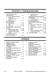
...Electrical 11-41 III. Making Initial Checks ....... 11-48 B. Switches 11-80 C. COMPOSITE POWER SUPPLY CIRCUIT DIAGRAM A-19 G. CHAPTER 11 TROUBLESHOOTING I . Faulty Feeding 11-78 VI. ADF 11-83 F. ADF CONTROLLER CIRCUIT DIAGRAM A-15 F. CONTROL PANEL CIRCUIT DIAGRAM A-27 H. NOISE...79 B. Lamp, Heater, Motor, Etc. 11-81 D. GENERAL TIMING CHART ........ GENERAL CIRCUIT DIAGRAM A-5 D. SENSOR CIRCUIT DIAGRAM A-30 J. CANON PC800s/900s REV.0 AUG. 1999 PRINTED IN JAPAN (IMPRIME AU JAPON) MAINTENANCE AND INSPECTION 11-3 A. Mechanical 11-5 B. Copy Paper Jam 11...
...Electrical 11-41 III. Making Initial Checks ....... 11-48 B. Switches 11-80 C. COMPOSITE POWER SUPPLY CIRCUIT DIAGRAM A-19 G. CHAPTER 11 TROUBLESHOOTING I . Faulty Feeding 11-78 VI. ADF 11-83 F. ADF CONTROLLER CIRCUIT DIAGRAM A-15 F. CONTROL PANEL CIRCUIT DIAGRAM A-27 H. NOISE...79 B. Lamp, Heater, Motor, Etc. 11-81 D. GENERAL TIMING CHART ........ GENERAL CIRCUIT DIAGRAM A-5 D. SENSOR CIRCUIT DIAGRAM A-30 J. CANON PC800s/900s REV.0 AUG. 1999 PRINTED IN JAPAN (IMPRIME AU JAPON) MAINTENANCE AND INSPECTION 11-3 A. Mechanical 11-5 B. Copy Paper Jam 11...
Service Manual
Page 264
... AND INSPECTION 11-3 A. Mechanical 11-5 B. Troubleshooting Image Faults 11-53 IV. Copy Paper Jam 11-75 B. ADF 11-83 F. TROUBLESHOOTING IMAGE FAULTS 11-48 A. ARRANGEMENT AND FUNCTIONS OF ELECTRICAL PARTS 11-79 A. CANON PC800s/900s REV.0 AUG. 1999 PRINTED IN JAPAN... (IMPRIME AU JAPON) TROUBLESHOOTING MALFUNCTIONS 11-61 A. CHAPTER 11 TROUBLESHOOTING I. Sensors and Solenoids .... 11-79 ...
... AND INSPECTION 11-3 A. Mechanical 11-5 B. Troubleshooting Image Faults 11-53 IV. Copy Paper Jam 11-75 B. ADF 11-83 F. TROUBLESHOOTING IMAGE FAULTS 11-48 A. ARRANGEMENT AND FUNCTIONS OF ELECTRICAL PARTS 11-79 A. CANON PC800s/900s REV.0 AUG. 1999 PRINTED IN JAPAN... (IMPRIME AU JAPON) TROUBLESHOOTING MALFUNCTIONS 11-61 A. CHAPTER 11 TROUBLESHOOTING I. Sensors and Solenoids .... 11-79 ...
Service Manual
Page 266
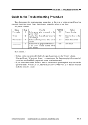
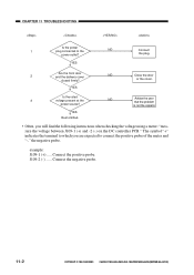
... plug. if yes, take , go to step 6. (Rest omitted.) • To find out the checks to make the indicated checks. CHAPTER 11 TROUBLESHOOTING Guide to use them: AC power is absent. Cause Power plug Covers Power source Step 1 2 3 4 Checks Is the power plug connected to take...action to the power outlet? Otherwise, go through the steps: answer the questions under "Checks"; CANON PC800s/900s REV.0 AUG. 1999 PRINTED IN JAPAN (IMPRIME AU JAPON) 11-1 COPYRIGHT © 1999 CANON INC. Inform the user that the power plug is disconnected, covers are not closed fully? ...
... plug. if yes, take , go to step 6. (Rest omitted.) • To find out the checks to make the indicated checks. CHAPTER 11 TROUBLESHOOTING Guide to use them: AC power is absent. Cause Power plug Covers Power source Step 1 2 3 4 Checks Is the power plug connected to take...action to the power outlet? Otherwise, go through the steps: answer the questions under "Checks"; CANON PC800s/900s REV.0 AUG. 1999 PRINTED IN JAPAN (IMPRIME AU JAPON) 11-1 COPYRIGHT © 1999 CANON INC. Inform the user that the power plug is disconnected, covers are not closed fully? ...
Service Manual
Page 267
... JAPAN (IMPRIME AU JAPON) J109-2 (-) ...... is not the copier's. CHAPTER 11 TROUBLESHOOTING Is the power 1 plug connected to connect the positive probe of the meter and "-," the negative probe. or the cover. Connect the negative probe. 11-2 COPYRIGHT © 1999 CANON INC. YES 3 Is the rated voltage present at the NO Advise...
... JAPAN (IMPRIME AU JAPON) J109-2 (-) ...... is not the copier's. CHAPTER 11 TROUBLESHOOTING Is the power 1 plug connected to connect the positive probe of the meter and "-," the negative probe. or the cover. Connect the negative probe. 11-2 COPYRIGHT © 1999 CANON INC. YES 3 Is the rated voltage present at the NO Advise...
Service Manual
Page 268
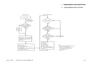
... visible? Cartridge 2. DC controller PCB 5. The machine is equipped with a function to the middle index; COPYRIGHT © 1999 CANON INC. Making Pre-Checks Clean the parts. Presence/absence of difference between front and rear (Note 2) 3. Scanning lamp 3. Applies...a copy density correction switch (SW101). 2. See p. 11-42. Composite power supply PCB (See the appropriate troubleshooting procedure.) END Note: 1. See the appropriate troubleshooting procedure. 3. NO YES Can the deviation be corrected using the copy density correction switch (SW101)? (Note ...
... visible? Cartridge 2. DC controller PCB 5. The machine is equipped with a function to the middle index; COPYRIGHT © 1999 CANON INC. Making Pre-Checks Clean the parts. Presence/absence of difference between front and rear (Note 2) 3. Scanning lamp 3. Applies...a copy density correction switch (SW101). 2. See p. 11-42. Composite power supply PCB (See the appropriate troubleshooting procedure.) END Note: 1. See the appropriate troubleshooting procedure. 3. NO YES Can the deviation be corrected using the copy density correction switch (SW101)? (Note ...
Service Manual
Page 270
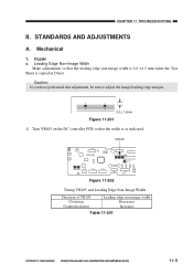
... VR105 and Leading Edge Non-Image Width Direction of VR105 Clockwise Counterclockwise Leading edge non-image width Decreases Increases Table 11-201 COPYRIGHT © 1999 CANON INC. Leading Edge Non-Image Width Make adjustments so that the width is copied in Direct. Caution: If you have performed this adjustment, be sure... the DC controller PCB so that the leading edge non-image width is 2.0 ±1.5 mm when the Test Sheet is as indicated. STANDARDS AND ADJUSTMENTS A. CANON PC800s/900s REV.0 AUG. 1999 PRINTED IN JAPAN (IMPRIME AU JAPON) 11-5 CHAPTER 11 TROUBLESHOOTING II.
... VR105 and Leading Edge Non-Image Width Direction of VR105 Clockwise Counterclockwise Leading edge non-image width Decreases Increases Table 11-201 COPYRIGHT © 1999 CANON INC. Leading Edge Non-Image Width Make adjustments so that the width is copied in Direct. Caution: If you have performed this adjustment, be sure... the DC controller PCB so that the leading edge non-image width is 2.0 ±1.5 mm when the Test Sheet is as indicated. STANDARDS AND ADJUSTMENTS A. CANON PC800s/900s REV.0 AUG. 1999 PRINTED IN JAPAN (IMPRIME AU JAPON) 11-5 CHAPTER 11 TROUBLESHOOTING II.

Service Manual
Page 271
... VR104 and Image Leading Edge Margin Direction of VR104 Clockwise Counterclockwise Image leading edge margin Increases Decreases Table 11-202 11-6 COPYRIGHT © 1999 CANON INC. CHAPTER 11 TROUBLESHOOTING b. CANON PC800s/900s REV.0 AUG. 1999 PRINTED IN JAPAN (IMPRIME AU JAPON) Caution: Be sure to check that the leading edge non-image width...
... VR104 and Image Leading Edge Margin Direction of VR104 Clockwise Counterclockwise Image leading edge margin Increases Decreases Table 11-202 11-6 COPYRIGHT © 1999 CANON INC. CHAPTER 11 TROUBLESHOOTING b. CANON PC800s/900s REV.0 AUG. 1999 PRINTED IN JAPAN (IMPRIME AU JAPON) Caution: Be sure to check that the leading edge non-image width...

Service Manual
Page 272
... copies are made, the cable tends to secure the cable retainer at the rear and the front of the No. 1 mirror mount. CHAPTER 11 TROUBLESHOOTING c. Reference: 1. If the optical length between No. 1 mirror and No. 2 mirror) If you have replaced the scanner drive cable, you ...adjust the mirror position, by changing the position of the cable retainer of the No. 1 mirror mount [1]. [1] Figure 11-206 COPYRIGHT © 1999 CANON INC. "Removing the Copyboard Glass".) 3) Loosen the screws used to become slack, requiring adjustment. 2. Figure 11-205 2) Remove the copyboard glass. (See...
... copies are made, the cable tends to secure the cable retainer at the rear and the front of the No. 1 mirror mount. CHAPTER 11 TROUBLESHOOTING c. Reference: 1. If the optical length between No. 1 mirror and No. 2 mirror) If you have replaced the scanner drive cable, you ...adjust the mirror position, by changing the position of the cable retainer of the No. 1 mirror mount [1]. [1] Figure 11-206 COPYRIGHT © 1999 CANON INC. "Removing the Copyboard Glass".) 3) Loosen the screws used to become slack, requiring adjustment. 2. Figure 11-205 2) Remove the copyboard glass. (See...

Service Manual
Page 273
CHAPTER 11 TROUBLESHOOTING 4) Turn the cable drive pulley [3] so that the three shafts [2] of the mirror positioning tool for the front and the rear may be arranged as shown. [2] [3] [2] Figure 11-207 (rear) [2] [2] Figure 11-208 (front) 11-8 COPYRIGHT © 1999 CANON INC. CANON PC800s/900s REV.0 AUG. 1999 PRINTED IN JAPAN (IMPRIME AU JAPON)
CHAPTER 11 TROUBLESHOOTING 4) Turn the cable drive pulley [3] so that the three shafts [2] of the mirror positioning tool for the front and the rear may be arranged as shown. [2] [3] [2] Figure 11-207 (rear) [2] [2] Figure 11-208 (front) 11-8 COPYRIGHT © 1999 CANON INC. CANON PC800s/900s REV.0 AUG. 1999 PRINTED IN JAPAN (IMPRIME AU JAPON)

Service Manual
Page 274
CANON PC800s/900s REV.0 AUG. 1999 PRINTED IN JAPAN (IMPRIME AU JAPON) 11-9 CHAPTER 11 TROUBLESHOOTING 5) While keeping the condition of 4), tighten the positioning screw at the rear and the front of the No. 1 mirror mount [1]. [1] Figure 11-209 (rear) [1] Figure 11-210 (front) COPYRIGHT © 1999 CANON INC.
CANON PC800s/900s REV.0 AUG. 1999 PRINTED IN JAPAN (IMPRIME AU JAPON) 11-9 CHAPTER 11 TROUBLESHOOTING 5) While keeping the condition of 4), tighten the positioning screw at the rear and the front of the No. 1 mirror mount [1]. [1] Figure 11-209 (rear) [1] Figure 11-210 (front) COPYRIGHT © 1999 CANON INC.

Service Manual
Page 275
... that the reading of the spring gauge is not correct, pickup faults or the like can occur. CANON PC800s/900s REV.0 AUG. 1999 PRINTED IN JAPAN (IMPRIME AU JAPON) CHAPTER 11 TROUBLESHOOTING d. Spring gauge (CK-0054) Holding plate 18mm Cassette spring Cassette Figure 11-211 11-10 COPYRIGHT ...© 1999 CANON INC. If a fault is suspected, check the force of the spring using a spring gauge (CK-...
... that the reading of the spring gauge is not correct, pickup faults or the like can occur. CANON PC800s/900s REV.0 AUG. 1999 PRINTED IN JAPAN (IMPRIME AU JAPON) CHAPTER 11 TROUBLESHOOTING d. Spring gauge (CK-0054) Holding plate 18mm Cassette spring Cassette Figure 11-211 11-10 COPYRIGHT ...© 1999 CANON INC. If a fault is suspected, check the force of the spring using a spring gauge (CK-...

Service Manual
Page 276
Routing the Scanner Drive Cable CHAPTER 11 TROUBLESHOOTING Wind 1.5 times. (black cable) Wind 7.5 times. (silvercolored cable) Figure 11-212 COPYRIGHT © 1999 CANON INC. CANON PC800s/900s REV.0 AUG. 1999 PRINTED IN JAPAN (IMPRIME AU JAPON) 11-11 e-1.
Routing the Scanner Drive Cable CHAPTER 11 TROUBLESHOOTING Wind 1.5 times. (black cable) Wind 7.5 times. (silvercolored cable) Figure 11-212 COPYRIGHT © 1999 CANON INC. CANON PC800s/900s REV.0 AUG. 1999 PRINTED IN JAPAN (IMPRIME AU JAPON) 11-11 e-1.

Service Manual
Page 277
....C.1."Removing the Copyboard Glass.") 4) Disconnect the connectors (J101, J131) [1] from the DC controller PCB. 11-12 [1] Figure 11-214 COPYRIGHT © 1999 CANON INC. Routing the Scanner Drive Cable 1. CANON PC800s/900s REV.0 AUG. 1999 PRINTED IN JAPAN (IMPRIME AU JAPON) Before Starting the Work Prepare the following: • Mirror positioning tool...
....C.1."Removing the Copyboard Glass.") 4) Disconnect the connectors (J101, J131) [1] from the DC controller PCB. 11-12 [1] Figure 11-214 COPYRIGHT © 1999 CANON INC. Routing the Scanner Drive Cable 1. CANON PC800s/900s REV.0 AUG. 1999 PRINTED IN JAPAN (IMPRIME AU JAPON) Before Starting the Work Prepare the following: • Mirror positioning tool...

Service Manual
Page 278
CHAPTER 11 TROUBLESHOOTING 5) If the machine is equipped with an ADF, free the hook [2], and disconnect the two relay connectors [3] from the left upper stay [4]. [3] [2] [2] [4] [2] [2] [3] Figure 11-215 6) Remove the three screws [5], and detach the left upper stay [4]. [5] [5] [4] Figure 11-216 COPYRIGHT © 1999 CANON INC. CANON PC800s/900s REV.0 AUG. 1999 PRINTED IN JAPAN (IMPRIME AU JAPON) 11-13
CHAPTER 11 TROUBLESHOOTING 5) If the machine is equipped with an ADF, free the hook [2], and disconnect the two relay connectors [3] from the left upper stay [4]. [3] [2] [2] [4] [2] [2] [3] Figure 11-215 6) Remove the three screws [5], and detach the left upper stay [4]. [5] [5] [4] Figure 11-216 COPYRIGHT © 1999 CANON INC. CANON PC800s/900s REV.0 AUG. 1999 PRINTED IN JAPAN (IMPRIME AU JAPON) 11-13

Service Manual
Page 279
CANON PC800s/900s REV.0 AUG. 1999 PRINTED IN JAPAN (IMPRIME AU JAPON) CHAPTER 11 TROUBLESHOOTING 7) Remove the four screws [7], and detach the lens cover [8]. [7] [7] [8] Figure 11-217 11-14 COPYRIGHT © 1999 CANON INC.
CANON PC800s/900s REV.0 AUG. 1999 PRINTED IN JAPAN (IMPRIME AU JAPON) CHAPTER 11 TROUBLESHOOTING 7) Remove the four screws [7], and detach the lens cover [8]. [7] [7] [8] Figure 11-217 11-14 COPYRIGHT © 1999 CANON INC.

Service Manual
Page 280
Routing the Reversing Cable 1) Wind the reversing cables (silver-colored) [2] on top; CANON PC800s/900s REV.0 AUG. 1999 PRINTED IN JAPAN (IMPRIME AU JAPON) 11-15 then, secure it in position with a cable clip [3]. [1] Longer end Shorter end [2] Face with the longer of the two on the cable drive pulley [1] 7.5 times with a marking Figure 11-218 [1] [3] [3] Top view Figure 11-219 COPYRIGHT © 1999 CANON INC. CHAPTER 11 TROUBLESHOOTING 2.
Routing the Reversing Cable 1) Wind the reversing cables (silver-colored) [2] on top; CANON PC800s/900s REV.0 AUG. 1999 PRINTED IN JAPAN (IMPRIME AU JAPON) 11-15 then, secure it in position with a cable clip [3]. [1] Longer end Shorter end [2] Face with the longer of the two on the cable drive pulley [1] 7.5 times with a marking Figure 11-218 [1] [3] [3] Top view Figure 11-219 COPYRIGHT © 1999 CANON INC. CHAPTER 11 TROUBLESHOOTING 2.

Service Manual
Page 281
CANON PC800s/900s REV.0 AUG. 1999 PRINTED IN JAPAN (IMPRIME AU JAPON) When putting the cable drive pulley into the shaft [4], and secure it in position with an E-ring [5]. CHAPTER 11 TROUBLESHOOTING 2) Put the cable drive pulley [1] into the shaft, be sure that the hook is at the front. [5] Hook [1] (front) [4] Figure 11-220 3) Hook the shorter end [6] on the pulley [7]. [7] [6] Figure 11-221 11-16 COPYRIGHT © 1999 CANON INC.
CANON PC800s/900s REV.0 AUG. 1999 PRINTED IN JAPAN (IMPRIME AU JAPON) When putting the cable drive pulley into the shaft [4], and secure it in position with an E-ring [5]. CHAPTER 11 TROUBLESHOOTING 2) Put the cable drive pulley [1] into the shaft, be sure that the hook is at the front. [5] Hook [1] (front) [4] Figure 11-220 3) Hook the shorter end [6] on the pulley [7]. [7] [6] Figure 11-221 11-16 COPYRIGHT © 1999 CANON INC.

Service Manual
Page 282
... the hole in the left rear pulley [10] and the pulley [11] of the cable matches. [13] [12] [6] Figure 11-223 COPYRIGHT © 1999 CANON INC. CANON PC800s/900s REV.0 AUG. 1999 PRINTED IN JAPAN (IMPRIME AU JAPON) 11-17 then, hook it on the left side plate and the tip of... mount. [11] [9] [8] [10] [6] Figure 11-222 5) After fitting the shorter end [6] on the cable hook [12], secure its end with adhesive tape [13]. CHAPTER 11 TROUBLESHOOTING 4) Lead the shorter end [6] under the No. 1 mirror mount [8] and the No. 2/3 mirror mount [9];
... the hole in the left rear pulley [10] and the pulley [11] of the cable matches. [13] [12] [6] Figure 11-223 COPYRIGHT © 1999 CANON INC. CANON PC800s/900s REV.0 AUG. 1999 PRINTED IN JAPAN (IMPRIME AU JAPON) 11-17 then, hook it on the left side plate and the tip of... mount. [11] [9] [8] [10] [6] Figure 11-222 5) After fitting the shorter end [6] on the cable hook [12], secure its end with adhesive tape [13]. CHAPTER 11 TROUBLESHOOTING 4) Lead the shorter end [6] under the No. 1 mirror mount [8] and the No. 2/3 mirror mount [9];

Service Manual
Page 283
then, hook it on the pulley [15] on the left front side and the pulley [17] of the No. 2/3 mirror mount. [17] [8] [16] [14] [9] Figure 11-225 11-18 COPYRIGHT © 1999 CANON INC. CHAPTER 11 TROUBLESHOOTING 6) Lead the longer end [14] along the cable drive pulley, and hook it on the pulley [16] on the right front side. [14] [15] [1] Figure 11-224 7) Lead the longer end [14] under the No. 1 mirror mount [8] and the No. 2/3 mirror mount [9]; CANON PC800s/900s REV.0 AUG. 1999 PRINTED IN JAPAN (IMPRIME AU JAPON)
then, hook it on the pulley [15] on the left front side and the pulley [17] of the No. 2/3 mirror mount. [17] [8] [16] [14] [9] Figure 11-225 11-18 COPYRIGHT © 1999 CANON INC. CHAPTER 11 TROUBLESHOOTING 6) Lead the longer end [14] along the cable drive pulley, and hook it on the pulley [16] on the right front side. [14] [15] [1] Figure 11-224 7) Lead the longer end [14] under the No. 1 mirror mount [8] and the No. 2/3 mirror mount [9]; CANON PC800s/900s REV.0 AUG. 1999 PRINTED IN JAPAN (IMPRIME AU JAPON)
