
Service Manual
Page 3
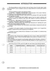
... for quick response to the user's needs. The PC720, PC740, PC750, and PC770 differ from time to time to reflect improvements rendered to the copier; This Service Manual consists of this manual, Service Handbook, and Service Information Bulletins,...10 10 12 COPYRIGHT © 1994 CANON INC. CHAPTER 3 "OPERATIONS AND TIMING" explains how the copier's electrical and mechanical systems are given. CHAPTER 5 "INSTALLATION" gives step-by-step instructions for installing the copier together with the generation of replacement parts and consumables. a Service Information Bulletin will...
... for quick response to the user's needs. The PC720, PC740, PC750, and PC770 differ from time to time to reflect improvements rendered to the copier; This Service Manual consists of this manual, Service Handbook, and Service Information Bulletins,...10 10 12 COPYRIGHT © 1994 CANON INC. CHAPTER 3 "OPERATIONS AND TIMING" explains how the copier's electrical and mechanical systems are given. CHAPTER 5 "INSTALLATION" gives step-by-step instructions for installing the copier together with the generation of replacement parts and consumables. a Service Information Bulletin will...
Service Manual
Page 5
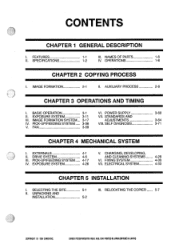
...VIII. SELF DIAGNOSIS 3-71 V. FAN 3-59 CHAPTER 4 MECHANICAL SYSTEM I . CHARGING, DEVELOPING, II. SELECTING THE SITE II. CANON PC7201740,11501170 REV.O AUG. 1994 PRINTED IN JAPAN (IMPRIME AU JAPON) AUXILIARY PROCESS 2-8 CHAPTER 3 OPERATIONS AND TIMING I ....SPECIFICATIONS 1-1 III. EXTERNALS 4-1 V. PICK-UP/FEEDING SYSTEM 4-17 VI. NAMES OF PARTS 1-6 1-2 IV. OPERATIONS 1-8 CHAPTER 2 COPYING PROCESS I . IMAGE FORMATION 2-1 II. RELOCATING THE COPIER 5-7 5-2 COPYRIGHT © 1994 CANON INC. POWER SUPPLY 3-60 II. ELECTRICAL SYSTEM 4-33 CHAPTER 5 INSTALLATION I . ...
...VIII. SELF DIAGNOSIS 3-71 V. FAN 3-59 CHAPTER 4 MECHANICAL SYSTEM I . CHARGING, DEVELOPING, II. SELECTING THE SITE II. CANON PC7201740,11501170 REV.O AUG. 1994 PRINTED IN JAPAN (IMPRIME AU JAPON) AUXILIARY PROCESS 2-8 CHAPTER 3 OPERATIONS AND TIMING I ....SPECIFICATIONS 1-1 III. EXTERNALS 4-1 V. PICK-UP/FEEDING SYSTEM 4-17 VI. NAMES OF PARTS 1-6 1-2 IV. OPERATIONS 1-8 CHAPTER 2 COPYING PROCESS I . IMAGE FORMATION 2-1 II. RELOCATING THE COPIER 5-7 5-2 COPYRIGHT © 1994 CANON INC. POWER SUPPLY 3-60 II. ELECTRICAL SYSTEM 4-33 CHAPTER 5 INSTALLATION I . ...
Service Manual
Page 92
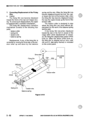
... Swing arm Tension wire Balance spring Figure 3-415 3 - 52 COPYRIGHT © 1994 CANON INC. CANON PC720114050/770 REV.O AUG.1994 PRINTEDIN JAPAN omplut AU JAPON) To correct such displacement, the copier is corrected, the fixing film displacement sensor (PS4) turns on , the fixing film ...tension roller; Outline The fixing film can move without displacement by moving . The fixing film displacement correction mechanism consists of the following four parts: • tension roller • swing arm • tension wire • balance spring Displacement, if any, of the range within...
... Swing arm Tension wire Balance spring Figure 3-415 3 - 52 COPYRIGHT © 1994 CANON INC. CANON PC720114050/770 REV.O AUG.1994 PRINTEDIN JAPAN omplut AU JAPON) To correct such displacement, the copier is corrected, the fixing film displacement sensor (PS4) turns on , the fixing film ...tension roller; Outline The fixing film can move without displacement by moving . The fixing film displacement correction mechanism consists of the following four parts: • tension roller • swing arm • tension wire • balance spring Displacement, if any, of the range within...
Service Manual
Page 105
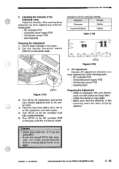
.... OPERATIONS AND TIMINGINN 2. avoid one with even density; CANON PC7201740R50M0 REV.O AUG.1994 PRINTED IN JAPAN ompagit AU JAPON) 3 - 65 Direction of the following parts: • DC controller PCB • composite power supply PCB • AE/intensity sensor PCB • scanning lamp Preparing for ...• Composite power supply PCB • AE/intensity sensor PCB • scanning lamp Preparing for Adjustment 1) Set the black cartridge in the copier. 2) Set the density correction switch (SW101) to the center notch. 0 SW101 Figure 3-701 3) Turn off the AE mechanism, and set ...
.... OPERATIONS AND TIMINGINN 2. avoid one with even density; CANON PC7201740R50M0 REV.O AUG.1994 PRINTED IN JAPAN ompagit AU JAPON) 3 - 65 Direction of the following parts: • DC controller PCB • composite power supply PCB • AE/intensity sensor PCB • scanning lamp Preparing for ...• Composite power supply PCB • AE/intensity sensor PCB • scanning lamp Preparing for Adjustment 1) Set the black cartridge in the copier. 2) Set the density correction switch (SW101) to the center notch. 0 SW101 Figure 3-701 3) Turn off the AE mechanism, and set ...

Service Manual
Page 163
SCHEDULED SERVICING The copier has no part that must be replaced on a periodical basis. MAINTENANCE AND SERVICINGMI PERIODICALLY REPLACED PARTS The copier does not have a part classified as a durable or consumable part. III. CANON PC720/140R50M0 REU AUG.1994 PRINTEDIN JAPAN oMPRIME AU JAPON) 6 - 1 COPYRIGHT © 1994 CANON INC. II. DURABLES AND CONSUMABLES The copier does not have a part to be serviced on a periodical basis.
SCHEDULED SERVICING The copier has no part that must be replaced on a periodical basis. MAINTENANCE AND SERVICINGMI PERIODICALLY REPLACED PARTS The copier does not have a part classified as a durable or consumable part. III. CANON PC720/140R50M0 REU AUG.1994 PRINTEDIN JAPAN oMPRIME AU JAPON) 6 - 1 COPYRIGHT © 1994 CANON INC. II. DURABLES AND CONSUMABLES The copier does not have a part to be serviced on a periodical basis.


