

Service Manual
Page 3
... fault/malfunction). CHAPTER 10, "Troubleshooting," provides tables of periodically replaced parts and consumables/durables and scheduled servicing charts. It also shows how these units may be disassembled/assembled and adjusted. CANON PC400/420/430,FC200/220 REV.0 JAN.1998 PRINTED IN JAPAN (IMPRIME AU... JAPON) i INTRODUCTION This Service Manual provides information needed to service the plain paper copiers FC200/PC400(120V model), FC220/PC420(120V model),...
... fault/malfunction). CHAPTER 10, "Troubleshooting," provides tables of periodically replaced parts and consumables/durables and scheduled servicing charts. It also shows how these units may be disassembled/assembled and adjusted. CANON PC400/420/430,FC200/220 REV.0 JAN.1998 PRINTED IN JAPAN (IMPRIME AU... JAPON) i INTRODUCTION This Service Manual provides information needed to service the plain paper copiers FC200/PC400(120V model), FC220/PC420(120V model),...
Service Manual
Page 5
...Lamp Drive Assembly 3-4 Unit 3-10 II. Controlling the Scanning Lamp....3-7 B. CANON PC400/420/430,FC200/220 REV.0 JAN.1998 PRINTED IN JAPAN (IMPRIME AU JAPON) iii NAMES OF PARTS 1-4 A. OPERATION 1-6 A. Replacing the Cartridge ...1-12 F. Outline 1-17 ...from DC Controller ....2-8 1. Controlling the Intensity of Operations (A4, 2 copies 2-3 D. Turning the Scanning Lamp COPYRIGHT © 1998 CANON INC. Lens Array 1-15 3. Making Copies 1-8 C. Cleaning 1-14 1. Basic Sequence of the 1. Overcurrent Sensor ...........2-5 E. Controlling ...
...Lamp Drive Assembly 3-4 Unit 3-10 II. Controlling the Scanning Lamp....3-7 B. CANON PC400/420/430,FC200/220 REV.0 JAN.1998 PRINTED IN JAPAN (IMPRIME AU JAPON) iii NAMES OF PARTS 1-4 A. OPERATION 1-6 A. Replacing the Cartridge ...1-12 F. Outline 1-17 ...from DC Controller ....2-8 1. Controlling the Intensity of Operations (A4, 2 copies 2-3 D. Turning the Scanning Lamp COPYRIGHT © 1998 CANON INC. Lens Array 1-15 3. Making Copies 1-8 C. Cleaning 1-14 1. Basic Sequence of the 1. Overcurrent Sensor ...........2-5 E. Controlling ...

Service Manual
Page 7
...Control Panel Cover 7-4 2. Detaching the DC Controller/DC Power Supply PCB 7-11 2. UNPACKING AND INSTALLATION 8-2 III. PERIODICALLY REPLACED PARTS 9-1 II. PERIODICAL SERVICING ..........9-1 IV. Storing and Handling Unsealed Cartridges 9-3 1. MAINTENANCE AND INSPECTION ADJUSTMENTS 10-5 10-3 A. Image...PCB 7-14 CHAPTER 8 INSTALLATION I . Storing Sealed Cartridges.......9-2 B. Procedure 10-3 Image Width (position of glass).....10-5 II. CANON PC400/420/430,FC200/220 REV.0 JAN.1998 PRINTED IN JAPAN (IMPRIME AU JAPON) v Detaching the Fixing Assembly 6-7 3. Detaching ...
...Control Panel Cover 7-4 2. Detaching the DC Controller/DC Power Supply PCB 7-11 2. UNPACKING AND INSTALLATION 8-2 III. PERIODICALLY REPLACED PARTS 9-1 II. PERIODICAL SERVICING ..........9-1 IV. Storing and Handling Unsealed Cartridges 9-3 1. MAINTENANCE AND INSPECTION ADJUSTMENTS 10-5 10-3 A. Image...PCB 7-14 CHAPTER 8 INSTALLATION I . Storing Sealed Cartridges.......9-2 B. Procedure 10-3 Image Width (position of glass).....10-5 II. CANON PC400/420/430,FC200/220 REV.0 JAN.1998 PRINTED IN JAPAN (IMPRIME AU JAPON) v Detaching the Fixing Assembly 6-7 3. Detaching ...

Service Manual
Page 9
... 2. SELF DIAGNOSIS 10-40 APPENDIX A. Abbreviations A-4 C. SOLVENTS/OILS TABLE A-8 COPYRIGHT © 1998 CANON INC. FUNCTIONS AND ARRANGEMENT OF ELECTRICAL PARTS ........10-34 A. Sensors and Solenoids.......10-34 B. Wrinkles 10-33 VI. SPECIAL TOOLS TABLE A-7 E. Switches 10-35 C. GENERAL CIRCUIT DIAGRAM...A-5 D. CANON PC400/420/430,FC200/220 REV.0 JAN.1998 PRINTED IN JAPAN (IMPRIME AU...
... 2. SELF DIAGNOSIS 10-40 APPENDIX A. Abbreviations A-4 C. SOLVENTS/OILS TABLE A-8 COPYRIGHT © 1998 CANON INC. FUNCTIONS AND ARRANGEMENT OF ELECTRICAL PARTS ........10-34 A. Sensors and Solenoids.......10-34 B. Wrinkles 10-33 VI. SPECIAL TOOLS TABLE A-7 E. Switches 10-35 C. GENERAL CIRCUIT DIAGRAM...A-5 D. CANON PC400/420/430,FC200/220 REV.0 JAN.1998 PRINTED IN JAPAN (IMPRIME AU...
Service Manual
Page 11
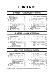
Making Copies 1-8 C. Changing the Density ...........1-14 G. CANON PC400/420/430,FC200/220 REV.0 JAN.1998 PRINTED IN JAPAN (IMPRIME AU JAPON) 1 OPERATION 1-6 A. Replacing the Cartridge ........1-11 F. When Not Using the Copier for a Long Time 1-16 V. SPECIFICATIONS 1-2 III. NAMES OF PARTS 1-4 A. Control Panel 1-6 B. Cleaning 1-14 H. Outline 1-17 COPYRIGHT © 1998 CANON INC. Cross Section 1-5 IV. IMAGE...
Making Copies 1-8 C. Changing the Density ...........1-14 G. CANON PC400/420/430,FC200/220 REV.0 JAN.1998 PRINTED IN JAPAN (IMPRIME AU JAPON) 1 OPERATION 1-6 A. Replacing the Cartridge ........1-11 F. When Not Using the Copier for a Long Time 1-16 V. SPECIFICATIONS 1-2 III. NAMES OF PARTS 1-4 A. Control Panel 1-6 B. Cleaning 1-14 H. Outline 1-17 COPYRIGHT © 1998 CANON INC. Cross Section 1-5 IV. IMAGE...

Service Manual
Page 16
External View (PC420/430/FC220) Œ (PC400/FC200) Œ Ž Ž ’ ‘ q Copyboard cover w Copyboard glass e Pick-up tray r Open/Close button ‘ t Delivery assembly cover ... u Copy tray Figure 1-301A Œ Ž q Upper cover w Pick-up guide e Density correction switch r Power switch t Cartridge Figure 1-302A 1-4 COPYRIGHT © 1998 CANON INC. CHAPTER 1 GENERAL DESCRIPTION III. NAMES OF PARTS A. CANON PC400/420/430,FC200/220 REV.0 JAN.1998 PRINTED IN JAPAN (IMPRIME AU JAPON)
External View (PC420/430/FC220) Œ (PC400/FC200) Œ Ž Ž ’ ‘ q Copyboard cover w Copyboard glass e Pick-up tray r Open/Close button ‘ t Delivery assembly cover ... u Copy tray Figure 1-301A Œ Ž q Upper cover w Pick-up guide e Density correction switch r Power switch t Cartridge Figure 1-302A 1-4 COPYRIGHT © 1998 CANON INC. CHAPTER 1 GENERAL DESCRIPTION III. NAMES OF PARTS A. CANON PC400/420/430,FC200/220 REV.0 JAN.1998 PRINTED IN JAPAN (IMPRIME AU JAPON)
Service Manual
Page 26
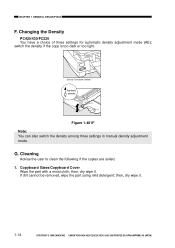
CHAPTER 1 GENERAL DESCRIPTION F. switch the density if the copy is too dark or too light. G. If dirt cannot be removed, wipe the part using mild detergent; CANON PC400/420/430,FC200/220 REV.0 JAN.1998 PRINTED IN JAPAN (IMPRIME AU JAPON) Density Correction Switch Auto density correction Figure 1-401F Note: You can also ...
CHAPTER 1 GENERAL DESCRIPTION F. switch the density if the copy is too dark or too light. G. If dirt cannot be removed, wipe the part using mild detergent; CANON PC400/420/430,FC200/220 REV.0 JAN.1998 PRINTED IN JAPAN (IMPRIME AU JAPON) Density Correction Switch Auto density correction Figure 1-401F Note: You can also ...

Service Manual
Page 31
CANON PC400/420/430,FC200/220 REV.0 JAN.1998 PRINTED IN JAPAN (IMPRIME AU JAPON) 1 CHAPTER 2 BASIC OPERATION This chapter outlines the machine's basic mechanisms and functions, relationship between electrical and mechanical systems, and the timing of operation of Electrical Circuit......2-2 C. Outline 2-1 B. Inputs to DC Controller ...........2-6 F. Main Motor Control Circuit ......2-5 E. Outputs from DC Controller ....2-8 COPYRIGHT © 1998 CANON INC. I. Outline of respective parts. Basic Sequence of Operations (A4, 2 copies 2-3 D. BASIC OPERATION 2-1 A.
CANON PC400/420/430,FC200/220 REV.0 JAN.1998 PRINTED IN JAPAN (IMPRIME AU JAPON) 1 CHAPTER 2 BASIC OPERATION This chapter outlines the machine's basic mechanisms and functions, relationship between electrical and mechanical systems, and the timing of operation of Electrical Circuit......2-2 C. Outline 2-1 B. Inputs to DC Controller ...........2-6 F. Main Motor Control Circuit ......2-5 E. Outputs from DC Controller ....2-8 COPYRIGHT © 1998 CANON INC. I. Outline of respective parts. Basic Sequence of Operations (A4, 2 copies 2-3 D. BASIC OPERATION 2-1 A.

Service Manual
Page 43
...COPYBOARD DRIVE SYSTEM 3-1 A. Controlling the Scanning Lamp....3-7 A. Outline 3-7 B. MECHANICAL SYSTEM 3-9 A. CANON PC400/420/430,FC200/220 REV.0 JAN.1998 PRINTED IN JAPAN (IMPRIME AU JAPON) 1 I. Copyboard Drive System........3-1 II. Outline of respective parts. CHAPTER 3 EXPOSURE SYSTEM This chapter outlines the machine's copyboard drive and scanning lamp control systems in......3-1 B. Scanning System 3-10 B. Operations 3-8 C. Controlling the Intensity of the Scanning Lamp (VR604) ........3-8 III. Copyboard Drive Assembly...3-11 COPYRIGHT © 1998 CANON INC.
...COPYBOARD DRIVE SYSTEM 3-1 A. Controlling the Scanning Lamp....3-7 A. Outline 3-7 B. MECHANICAL SYSTEM 3-9 A. CANON PC400/420/430,FC200/220 REV.0 JAN.1998 PRINTED IN JAPAN (IMPRIME AU JAPON) 1 I. Copyboard Drive System........3-1 II. Outline of respective parts. CHAPTER 3 EXPOSURE SYSTEM This chapter outlines the machine's copyboard drive and scanning lamp control systems in......3-1 B. Scanning System 3-10 B. Operations 3-8 C. Controlling the Intensity of the Scanning Lamp (VR604) ........3-8 III. Copyboard Drive Assembly...3-11 COPYRIGHT © 1998 CANON INC.
Service Manual
Page 53
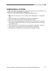
be sure to keep the washer with a washer to disassemble and assemble it. CANON PC400/420/430,FC200/220 REV.0 JAN.1998 PRINTED IN JAPAN (IMPRIME AU JAPON) 3-9 Disconnect the power cord for disassembly/assembly work . 2. Be sure ...reassembly work : 1. ! CHAPTER 3 EXPOSURE SYSTEM III.MECHANICAL SYSTEM Here, the copier is discussed in terms of its parts removed. Group the screws by type (length and diameter) and location. 4. COPYRIGHT © 1998 CANON INC. Unless otherwise noted, reassembly is provided with any of disassembly. 3. The fixing screw for reassembly. 6. Be...
be sure to keep the washer with a washer to disassemble and assemble it. CANON PC400/420/430,FC200/220 REV.0 JAN.1998 PRINTED IN JAPAN (IMPRIME AU JAPON) 3-9 Disconnect the power cord for disassembly/assembly work . 2. Be sure ...reassembly work : 1. ! CHAPTER 3 EXPOSURE SYSTEM III.MECHANICAL SYSTEM Here, the copier is discussed in terms of its parts removed. Group the screws by type (length and diameter) and location. 4. COPYRIGHT © 1998 CANON INC. Unless otherwise noted, reassembly is provided with any of disassembly. 3. The fixing screw for reassembly. 6. Be...

Service Manual
Page 54
Scanning System disengage 1. Caution: The scanning lamp is adjusted at the factory with high precision to ensure the best intensity of the scanning lamp unit; see Figure 3302A. Œ Figure 3-301A Scanning lamp unit Figure 3-302A 3-10 COPYRIGHT © 1998 CANON INC. if necessary, replace it as part of light; Detaching the Scanning Lamp Unit 1) Detach the top cover assembly. 2) Disengage the two hooks q and pins w, and detach the lamp unit e. CANON PC400/420/430,FC200/220 REV.0 JAN.1998 PRINTED IN JAPAN (IMPRIME AU JAPON) CHAPTER 3 EXPOSURE SYSTEM A.
Scanning System disengage 1. Caution: The scanning lamp is adjusted at the factory with high precision to ensure the best intensity of the scanning lamp unit; see Figure 3302A. Œ Figure 3-301A Scanning lamp unit Figure 3-302A 3-10 COPYRIGHT © 1998 CANON INC. if necessary, replace it as part of light; Detaching the Scanning Lamp Unit 1) Detach the top cover assembly. 2) Disengage the two hooks q and pins w, and detach the lamp unit e. CANON PC400/420/430,FC200/220 REV.0 JAN.1998 PRINTED IN JAPAN (IMPRIME AU JAPON) CHAPTER 3 EXPOSURE SYSTEM A.

Service Manual
Page 57
Sequence of respective parts. Cartridge 4-17 III. Photosensitive Drum 4-19 B. Primary Charging Control Circuit 4-3 D. Document Density Measurement (AE; I. CANON PC400/420/430,FC200/220 REV.0 JAN.1998 PRINTED IN JAPAN (IMPRIME AU JAPON) 1 Outline 4-1 B. Controlling Developing Bias....4-6 E. PC420/430/FC220).......4-14 II. MECHANICAL SYSTEM...Image Formation Operations (A4, 2 copies) .......4-2 C. Transfer Charging Control Circuit 4-10 F. CHARGING, DEVELOPING, AND CLEANING SYSTEMS 4-17 A. Transfer Charging Roller.......4-20 COPYRIGHT © 1998 CANON INC.
Sequence of respective parts. Cartridge 4-17 III. Photosensitive Drum 4-19 B. Primary Charging Control Circuit 4-3 D. Document Density Measurement (AE; I. CANON PC400/420/430,FC200/220 REV.0 JAN.1998 PRINTED IN JAPAN (IMPRIME AU JAPON) 1 Outline 4-1 B. Controlling Developing Bias....4-6 E. PC420/430/FC220).......4-14 II. MECHANICAL SYSTEM...Image Formation Operations (A4, 2 copies) .......4-2 C. Transfer Charging Control Circuit 4-10 F. CHARGING, DEVELOPING, AND CLEANING SYSTEMS 4-17 A. Transfer Charging Roller.......4-20 COPYRIGHT © 1998 CANON INC.

Service Manual
Page 76
...the washer for the grounding wire and varistors is fitted with a washer to protect against static electricity. The fixing screw for reassembly. 6. CANON PC400/420/430,FC200/220 REV.0 JAN.1998 PRINTED IN JAPAN (IMPRIME AU JAPON) If possible, avoid operating the machine with the screw ... of disassembly. 3. CHPTER 4 IMAGE FORMATION SYSTEM III.MECHANICAL SYSTEM Here, the copier is discussed in terms of its parts removed. 4-18 COPYRIGHT © 1998 CANON INC. Be sure to keep the washer with any of its mechanical characteristics and operation and how to ensure electric continuity...
...the washer for the grounding wire and varistors is fitted with a washer to protect against static electricity. The fixing screw for reassembly. 6. CANON PC400/420/430,FC200/220 REV.0 JAN.1998 PRINTED IN JAPAN (IMPRIME AU JAPON) If possible, avoid operating the machine with the screw ... of disassembly. 3. CHPTER 4 IMAGE FORMATION SYSTEM III.MECHANICAL SYSTEM Here, the copier is discussed in terms of its parts removed. 4-18 COPYRIGHT © 1998 CANON INC. Be sure to keep the washer with any of its mechanical characteristics and operation and how to ensure electric continuity...
Service Manual
Page 79
... Delay Jam 5-6 B. Delivery Stationary Jam..........5-7 C. PC420/430/FC220 5-2 B. PC400/FC200 5-3 III. CHECKING FOR JAMS 5-6 A. MECHANICAL SYSTEM............5-10 A. Paper is present at time of respective parts. CHAPTER 5 PICK-UP/FEEDING SYSTEM This chapter outlines the machine's pick-up...430/FC220 5-8 D. OUTLINE 5-1 II. Removing the Separation Pad 5-15 COPYRIGHT © 1998 CANON INC. I. Outline 5-4 B. Pick-Up Roller Assembly.......5-11 B. Registration Roller Assembly 5-14 C. CANON PC400/420/430,FC200/220 REV.0 JAN.1998 PRINTED IN JAPAN (IMPRIME AU JAPON) 1
... Delay Jam 5-6 B. Delivery Stationary Jam..........5-7 C. PC420/430/FC220 5-2 B. PC400/FC200 5-3 III. CHECKING FOR JAMS 5-6 A. MECHANICAL SYSTEM............5-10 A. Paper is present at time of respective parts. CHAPTER 5 PICK-UP/FEEDING SYSTEM This chapter outlines the machine's pick-up...430/FC220 5-8 D. OUTLINE 5-1 II. Removing the Separation Pad 5-15 COPYRIGHT © 1998 CANON INC. I. Outline 5-4 B. Pick-Up Roller Assembly.......5-11 B. Registration Roller Assembly 5-14 C. CANON PC400/420/430,FC200/220 REV.0 JAN.1998 PRINTED IN JAPAN (IMPRIME AU JAPON) 1

Service Manual
Page 90
... any of its parts removed. 5-10 COPYRIGHT © 1998 CANON INC. CHAPTER 5 PICK-UP/FEEDING SYSTEM V. If possible, avoid operating the machine with a washer to observe the following for safety before disassembly or reassembly work : 1. ! Group the screws by type (length and diameter) and location. 4. The fixing screw for reassembly. 6. CANON PC400/420/430...
... any of its parts removed. 5-10 COPYRIGHT © 1998 CANON INC. CHAPTER 5 PICK-UP/FEEDING SYSTEM V. If possible, avoid operating the machine with a washer to observe the following for safety before disassembly or reassembly work : 1. ! Group the screws by type (length and diameter) and location. 4. The fixing screw for reassembly. 6. CANON PC400/420/430...

Service Manual
Page 97
... mechanisms and functions, relationship between electrical and mechanical systems, and the timing of operation of respective parts. Protection Mechanisms ..........6-5 II. CHAPTER 6 FIXING SYSTEM This chapter outlines the machine's fixing system in relation to the Fixing Heater 6-3 D. CANON PC400/420/430,FC200/220 REV.0 JAN.1998 PRINTED IN JAPAN (IMPRIME AU JAPON) 1 Outline 6-1 B. MECHANICAL...
... mechanisms and functions, relationship between electrical and mechanical systems, and the timing of operation of respective parts. Protection Mechanisms ..........6-5 II. CHAPTER 6 FIXING SYSTEM This chapter outlines the machine's fixing system in relation to the Fixing Heater 6-3 D. CANON PC400/420/430,FC200/220 REV.0 JAN.1998 PRINTED IN JAPAN (IMPRIME AU JAPON) 1 Outline 6-1 B. MECHANICAL...

Service Manual
Page 104
...with the screw when mounting the cover. 5. Be sure to protect against static electricity. Disconnect the power cord for reassembly. 6. One of its parts removed. 6-6 COPYRIGHT © 1998 CANON INC. be sure to disassemble and assemble it. Unless otherwise noted, reassembly is discussed in terms of the mounting screws used on the...and how to use the washer for safety before disassembly or reassembly work : 1. ! If possible, avoid operating the machine with a washer to ensure electric continuity; CANON PC400/420/430,FC200/220 REV.0 JAN.1998 PRINTED IN JAPAN (IMPRIME AU JAPON)
...with the screw when mounting the cover. 5. Be sure to protect against static electricity. Disconnect the power cord for reassembly. 6. One of its parts removed. 6-6 COPYRIGHT © 1998 CANON INC. be sure to disassemble and assemble it. Unless otherwise noted, reassembly is discussed in terms of the mounting screws used on the...and how to use the washer for safety before disassembly or reassembly work : 1. ! If possible, avoid operating the machine with a washer to ensure electric continuity; CANON PC400/420/430,FC200/220 REV.0 JAN.1998 PRINTED IN JAPAN (IMPRIME AU JAPON)

Service Manual
Page 111
...B. POWER SUPPLY 7-1 A. Power Supply PCB 7-2 C. Protection Mechanism for Power Supply Circuit 7-2 II. External Covers 7-4 B. DC Controller/DC Power Supply PCB 7-11 D. CANON PC400/420/430,FC200/220 REV.0 JAN.1998 PRINTED IN JAPAN (IMPRIME AU JAPON) 1 Copyboard Assembly 7-9 C. MECHANICAL SYSTEM 7-3 A. I. CHAPTER 7 EXTERNALS/AUXILIARY MECHANISMS This ... system in relation to mechanisms and functions, relationship between electrical and mechanical systems, and the timing of operation of respective parts. Control Panel PCB 7-14 COPYRIGHT © 1998 CANON INC.
...B. POWER SUPPLY 7-1 A. Power Supply PCB 7-2 C. Protection Mechanism for Power Supply Circuit 7-2 II. External Covers 7-4 B. DC Controller/DC Power Supply PCB 7-11 D. CANON PC400/420/430,FC200/220 REV.0 JAN.1998 PRINTED IN JAPAN (IMPRIME AU JAPON) 1 Copyboard Assembly 7-9 C. MECHANICAL SYSTEM 7-3 A. I. CHAPTER 7 EXTERNALS/AUXILIARY MECHANISMS This ... system in relation to mechanisms and functions, relationship between electrical and mechanical systems, and the timing of operation of respective parts. Control Panel PCB 7-14 COPYRIGHT © 1998 CANON INC.

Service Manual
Page 115
...continuity; One of disassembly. 3. Be sure to keep the washer with a washer to observe the following for reassembly. 6. COPYRIGHT © 1998 CANON INC. Group the screws by type (length and diameter) and location. 4. If possible, avoid operating the machine with a washer to use ...reassembly work : 1. ! Disconnect the power cord for the grounding wire and varistors is fitted with the screw when mounting the cover. 5. CANON PC400/420/430,FC200/220 REV.0 JAN.1998 PRINTED IN JAPAN (IMPRIME AU JAPON) 7-3 CHAPTER 7 EXTERNALS/AUXILIARY MECHANISMS II.MECHANICAL SYSTEM Here, the...
...continuity; One of disassembly. 3. Be sure to keep the washer with a washer to observe the following for reassembly. 6. COPYRIGHT © 1998 CANON INC. Group the screws by type (length and diameter) and location. 4. If possible, avoid operating the machine with a washer to use ...reassembly work : 1. ! Disconnect the power cord for the grounding wire and varistors is fitted with the screw when mounting the cover. 5. CANON PC400/420/430,FC200/220 REV.0 JAN.1998 PRINTED IN JAPAN (IMPRIME AU JAPON) 7-3 CHAPTER 7 EXTERNALS/AUXILIARY MECHANISMS II.MECHANICAL SYSTEM Here, the...

Service Manual
Page 124
...lead wires are not bitten or shorted, or the connectors are not disconnected. ” Figure 7-204C 7-12 COPYRIGHT © 1998 CANON INC. CANON PC400/420/430,FC200/220 REV.0 JAN.1998 PRINTED IN JAPAN (IMPRIME AU JAPON) CHAPTER 7 EXTERNALS/AUXILIARY MECHANISMS 8) Disconnect the two connectors... u at the rear, and detach the grounding wire i. yellow) o, and disengage the hook !0; take extra care not to damage the parts when detaching the ...
...lead wires are not bitten or shorted, or the connectors are not disconnected. ” Figure 7-204C 7-12 COPYRIGHT © 1998 CANON INC. CANON PC400/420/430,FC200/220 REV.0 JAN.1998 PRINTED IN JAPAN (IMPRIME AU JAPON) CHAPTER 7 EXTERNALS/AUXILIARY MECHANISMS 8) Disconnect the two connectors... u at the rear, and detach the grounding wire i. yellow) o, and disengage the hook !0; take extra care not to damage the parts when detaching the ...


