
Service Manual
Page 7
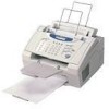
EQUIPMENT OUTLINE 1.1 External Appearance and Weight The figure below shows the equipment appearance and approximate dimensions. drum unit & toner cartridge) In package 1.2 Components The equipment consists of the following major components: Approx. 7.2 kg Approx. 8.5 kg Approx. 12 kg I - 1 *1 Not provided on the FAX8060P/MFC9060. *2 Provided on the FAX8060P/MFC9060. Weight: Machine proper Machine (incl. 1.
EQUIPMENT OUTLINE 1.1 External Appearance and Weight The figure below shows the equipment appearance and approximate dimensions. drum unit & toner cartridge) In package 1.2 Components The equipment consists of the following major components: Approx. 7.2 kg Approx. 8.5 kg Approx. 12 kg I - 1 *1 Not provided on the FAX8060P/MFC9060. *2 Provided on the FAX8060P/MFC9060. Weight: Machine proper Machine (incl. 1.

Service Manual
Page 10
.../Type PPM DPI (output resolution) Paper Capacity Emulation (Standard) Standards Memory (Typical) Memory (MIN.) Fonts Resident Fonts Disk Based Paper Handling Multi-Purpose Tray Toner Life (Starter) Toner Life (Supply) Drum Life Utility Software Period to go in Sleep Mode Output size Interface/Interface cable SCANNER Color/Mono dpi Gray Scale Twain...
.../Type PPM DPI (output resolution) Paper Capacity Emulation (Standard) Standards Memory (Typical) Memory (MIN.) Fonts Resident Fonts Disk Based Paper Handling Multi-Purpose Tray Toner Life (Starter) Toner Life (Supply) Drum Life Utility Software Period to go in Sleep Mode Output size Interface/Interface cable SCANNER Color/Mono dpi Gray Scale Twain...

Service Manual
Page 11
... (600x600) Memory (Typical) - 1 MB Memory (MIN.) - 600 KB Fonts Resident - - Windows95/98 and NT4.0/2000 Driver with Auto Installer Program Toner Life (Standard) 1,000 pages with 5% black 1,000 pages with 5% black Toner Life (Supply) 2,200 pages with 5% black 2,200 pages with 5% black Drum Life 20,000 pages (20 pages/job) 20,000...
... (600x600) Memory (Typical) - 1 MB Memory (MIN.) - 600 KB Fonts Resident - - Windows95/98 and NT4.0/2000 Driver with Auto Installer Program Toner Life (Standard) 1,000 pages with 5% black 1,000 pages with 5% black Toner Life (Supply) 2,200 pages with 5% black 2,200 pages with 5% black Drum Life 20,000 pages (20 pages/job) 20,000...

Service Manual
Page 25
The graph below shows the transition of electrical charge on the surface of the laser-sensitive drum through the five processes: charging, exposing, developing, transferring, and erasing processes. III - 6 2.2.2 Print process mechanism The print process unit works with laser beam, electrical charges, and toner.
The graph below shows the transition of electrical charge on the surface of the laser-sensitive drum through the five processes: charging, exposing, developing, transferring, and erasing processes. III - 6 2.2.2 Print process mechanism The print process unit works with laser beam, electrical charges, and toner.

Service Manual
Page 26
2.2.3 Heat-fixing mechanism As the paper passes between the heater roller and the pressure roller in the heat-fixing unit, the heater roller fuses the toner on the paper. III - 7
2.2.3 Heat-fixing mechanism As the paper passes between the heater roller and the pressure roller in the heat-fixing unit, the heater roller fuses the toner on the paper. III - 7

Service Manual
Page 27
...PCB ASSY (Document sensor PCB) Control panel PCB ASSY (Document sensor PCB) Main PCB Main PCB High-voltage power supply PCB Toner sensor PCB Toner sensor PCB Heat-fixing unit Hook switch PCB* *Not provided on the FAX8060P/MFC9060. • Document front sensor which detects ... which detects whether the recording paper goes out of the equipment. • Toner sensor which detects whether there is toner or a toner cartridge is loaded. • Toner thermister which detects the ambient temperature of the toner cartridge. • Heater thermister which detects the temperature of the heater roller ...
...PCB ASSY (Document sensor PCB) Control panel PCB ASSY (Document sensor PCB) Main PCB Main PCB High-voltage power supply PCB Toner sensor PCB Toner sensor PCB Heat-fixing unit Hook switch PCB* *Not provided on the FAX8060P/MFC9060. • Document front sensor which detects ... which detects whether the recording paper goes out of the equipment. • Toner sensor which detects whether there is toner or a toner cartridge is loaded. • Toner thermister which detects the ambient temperature of the toner cartridge. • Heater thermister which detects the temperature of the heater roller ...

Service Manual
Page 31
... except FAX8060P/MFC9060) Side Cover (for FAX8060P/MFC9060 IV-23 1.10 Heat-fixing Unit, FU Lamp, and Paper Ejection Sensor Actuator IV-25 1.11 Laser Unit and Toner Sensor PCB IV-27 1.12 Bottom Plate ...IV-28 1.13 Low-voltage Power Supply PCB IV-30 1.14 Main PCB ...IV-31 1.15 High...
... except FAX8060P/MFC9060) Side Cover (for FAX8060P/MFC9060 IV-23 1.10 Heat-fixing Unit, FU Lamp, and Paper Ejection Sensor Actuator IV-25 1.11 Laser Unit and Toner Sensor PCB IV-27 1.12 Bottom Plate ...IV-28 1.13 Low-voltage Power Supply PCB IV-30 1.14 Main PCB ...IV-31 1.15 High...

Service Manual
Page 34
... 2 Hinges on top cover Taptite, bind B M4x12 4 Hinges on main cover Taptite, cup B M4x12 4 Handset mount Taptite, cup B M3x10 2 Heat-fixing unit Taptite, bind B M4x12 1 Laser unit Toner sensor PCB Taptite, bind B M4x12 3 Taptite, cup B M3x8 1 Bottom plate AC grounding wire Interface connector Taptite, bind B M4x12 7 Taptite, cup S M3x6 3 Screw, pan (washer...
... 2 Hinges on top cover Taptite, bind B M4x12 4 Hinges on main cover Taptite, cup B M4x12 4 Handset mount Taptite, cup B M3x10 2 Heat-fixing unit Taptite, bind B M4x12 1 Laser unit Toner sensor PCB Taptite, bind B M4x12 3 Taptite, cup B M3x8 1 Bottom plate AC grounding wire Interface connector Taptite, bind B M4x12 7 Taptite, cup S M3x6 3 Screw, pan (washer...

Service Manual
Page 35
IV - 3 the document tray, - the modular jack of an external telephone set if connected. (Not shown below.) (2) Remove - the drum unit (with the toner cartridge loaded) (*Not provided on the flow and learn its number ( in the reverse order of the curled cord (and remove the handset), - Preparation Prior ...
IV - 3 the document tray, - the modular jack of an external telephone set if connected. (Not shown below.) (2) Remove - the drum unit (with the toner cartridge loaded) (*Not provided on the flow and learn its number ( in the reverse order of the curled cord (and remove the handset), - Preparation Prior ...

Service Manual
Page 59
...(3) Remove the three screws from the laser unit. (4) Slightly lift up the laser unit and disconnect the following from the main PCB: - Toner sensor harness (4-pin) if the toner sensor PCB is placed below the laser unit. Polygon motor flat cable NOTE: When handling the laser unit, take care not to touch ...the inside of the laser unit is a 2-pin connector which is for any toner particles, paper dust or dirt, and clean them out. • When installing the laser unit, make sure that the laser diode harness, toner sensor harness and polygon motor flat cable are routed ...
...(3) Remove the three screws from the laser unit. (4) Slightly lift up the laser unit and disconnect the following from the main PCB: - Toner sensor harness (4-pin) if the toner sensor PCB is placed below the laser unit. Polygon motor flat cable NOTE: When handling the laser unit, take care not to touch ...the inside of the laser unit is a 2-pin connector which is for any toner particles, paper dust or dirt, and clean them out. • When installing the laser unit, make sure that the laser diode harness, toner sensor harness and polygon motor flat cable are routed ...

Service Manual
Page 63
... disconnect it from the low-voltage power supply PCB. (3) Disconnect the following harnesses from the main PCB: • Speaker harness (2-pin, P7) • Laser diode harness (5-pin, P6) • Toner sensor harness (4-pin, P5) • Polygon motor flat cable (5-pin, P4) • NCU harness 2*1 (6-pin, P13) • NCU harness (12-pin, P14...
... disconnect it from the low-voltage power supply PCB. (3) Disconnect the following harnesses from the main PCB: • Speaker harness (2-pin, P7) • Laser diode harness (5-pin, P6) • Toner sensor harness (4-pin, P5) • Polygon motor flat cable (5-pin, P4) • NCU harness 2*1 (6-pin, P13) • NCU harness (12-pin, P14...

Service Manual
Page 66
IV - 34 Reassembling Notes • Before reinstalling the high-voltage power supply PCB, check the high-voltage contacts for any toner particles, paper dust or dirt, and clean them out. • Be sure to route the drum grounding harness through boss "x" and latches "y" and "z." • When ...
IV - 34 Reassembling Notes • Before reinstalling the high-voltage power supply PCB, check the high-voltage contacts for any toner particles, paper dust or dirt, and clean them out. • Be sure to route the drum grounding harness through boss "x" and latches "y" and "z." • When ...

Service Manual
Page 75
Grounding contacts High-voltage contacts IV - 43 1.23 Cleaning of High-voltage Contacts and Grounding Contacts If any toner particles, paper dust or dirt are on the contacts, clean them out. This will ensure that power flows correctly to enable printing.
Grounding contacts High-voltage contacts IV - 43 1.23 Cleaning of High-voltage Contacts and Grounding Contacts If any toner particles, paper dust or dirt are on the contacts, clean them out. This will ensure that power flows correctly to enable printing.

Service Manual
Page 120
... Not used . Selector 4: Detection of distinctive ringing pattern If this selector is set to compare the detected ringing pattern with the registered distinctive one. Ringer OFF setting Automatic playback of OGM at the start time of OGM ON mode Detection of rings; Selector 3: Automatic playback of OGM ... number of OGM ON mode This selector determines whether or not the equipment automatically plays back an OGM the moment it switches to OFF. Toner save mode 0: Yes 1: No Selector 2: Ringer OFF setting This selector determines whether or not the ringer can be set to the OGM...
... Not used . Selector 4: Detection of distinctive ringing pattern If this selector is set to compare the detected ringing pattern with the registered distinctive one. Ringer OFF setting Automatic playback of OGM at the start time of OGM ON mode Detection of rings; Selector 3: Automatic playback of OGM ... number of OGM ON mode This selector determines whether or not the equipment automatically plays back an OGM the moment it switches to OFF. Toner save mode 0: Yes 1: No Selector 2: Ringer OFF setting This selector determines whether or not the ringer can be set to the OGM...

Service Manual
Page 130
... binary notation. Selector No. 1 | 8 WSW50 (Function setting 28) Function Setting and Specifications Idle time of the main motor when the and keys are pressed at one time Set half of the value of the desired idle time to these selectors in binary notation. No. 1 2 3 4 000 0 000 0 | 000 0 | 111 1 5 6 78 0 0...: 2 sec. | : 12 sec. | : 510 sec. WSW49 (Function setting 27) Selector No. 1 | 8 Function Idle time of the main motor after replacement of the toner cartridge Setting and Specifications Set half of the value of the desired idle time to these selectors in binary notation.
... binary notation. Selector No. 1 | 8 WSW50 (Function setting 28) Function Setting and Specifications Idle time of the main motor when the and keys are pressed at one time Set half of the value of the desired idle time to these selectors in binary notation. No. 1 2 3 4 000 0 000 0 | 000 0 | 111 1 5 6 78 0 0...: 2 sec. | : 12 sec. | : 510 sec. WSW49 (Function setting 27) Selector No. 1 | 8 Function Idle time of the main motor after replacement of the toner cartridge Setting and Specifications Set half of the value of the desired idle time to these selectors in binary notation.
Service Manual
Page 134
... shows the "FRRECVRGHATN" when - In the FAX8060P/MFC9060, the LCD should show "FRRECVRGHATN" if the detecting conditions of the maintenance mode. the toner sensor detects toner (TN). the paper ejection sensor detects no paper (FR), - V - 54 the document rear sensor detects no paper (HA), and - ... allows you to the initial maintenance mode, press the Stop key. the paper ejection sensor detects no paper (RE), - the toner sensor detects toner (TN), and - The equipment sounds 1100 Hz and 400 Hz tones cyclically through the document sensors or the registration sensor, or...
... shows the "FRRECVRGHATN" when - In the FAX8060P/MFC9060, the LCD should show "FRRECVRGHATN" if the detecting conditions of the maintenance mode. the toner sensor detects toner (TN). the paper ejection sensor detects no paper (FR), - V - 54 the document rear sensor detects no paper (HA), and - ... allows you to the initial maintenance mode, press the Stop key. the paper ejection sensor detects no paper (RE), - the toner sensor detects toner (TN), and - The equipment sounds 1100 Hz and 400 Hz tones cyclically through the document sensors or the registration sensor, or...
Service Manual
Page 141
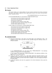
...appears for one minute. (You can turn this message appears, recording is not enough toner. SET CARTRIDGE The toner sensor has detected that the toner temperature exceeded the specified level. "XX" indicates an error code. If the temperature exceeds the preset level, recording is no toner. The service... printed by the maintenance-mode function code 10, WSW31, selector 8. Refer to [ 2 ] on pages VI-4 and VI-5. TONER EMPTY The toner sensor has detected that there is no longer possible. Messages on the LCD DOCUMENT JAM Probable Cause Document loading error (1) The document...
...appears for one minute. (You can turn this message appears, recording is not enough toner. SET CARTRIDGE The toner sensor has detected that the toner temperature exceeded the specified level. "XX" indicates an error code. If the temperature exceeds the preset level, recording is no toner. The service... printed by the maintenance-mode function code 10, WSW31, selector 8. Refer to [ 2 ] on pages VI-4 and VI-5. TONER EMPTY The toner sensor has detected that there is no longer possible. Messages on the LCD DOCUMENT JAM Probable Cause Document loading error (1) The document...

Service Manual
Page 143
...to scan. ) Document not detected by the document rear sensor. ) 50% or more faulty of white level data. ) One-line feeding time-out error. ) One-line scanning time-out error. ) Abnormal scanning reference voltage. ) Less than 50% faulty of white level data. ) Error... 83 ( 84 ( 88 ( A1 ( A2 ( A3 ( A4 ( A7 ( A8 ( A9 ( AC Error factor Laser scanner motor does not lock. ) Cannot detect Beam Detect signal. ) No toner cartridge loaded. ) Toner empty. ) In-house temperature error. ) Fixing heater harness disconnected or broken. ) Heater thermister short circuit.) Heater thermister harness ...
...to scan. ) Document not detected by the document rear sensor. ) 50% or more faulty of white level data. ) One-line feeding time-out error. ) One-line scanning time-out error. ) Abnormal scanning reference voltage. ) Less than 50% faulty of white level data. ) Error... 83 ( 84 ( 88 ( A1 ( A2 ( A3 ( A4 ( A7 ( A8 ( A9 ( AC Error factor Laser scanner motor does not lock. ) Cannot detect Beam Detect signal. ) No toner cartridge loaded. ) Toner empty. ) In-house temperature error. ) Fixing heater harness disconnected or broken. ) Heater thermister short circuit.) Heater thermister harness ...

Service Manual
Page 156
Main PCB At the printer side Replace the toner cartridge with a new one and print 4 to the next step. At the scanner Check the following components: - VI - 17 Remove the toner cartridge and start printing. Clean the high-voltage contacts for the transfer roller on the drum unit, main cover, and high...) Check the connection of the main-high-voltage flat cable. Replace the main PCB. CIS unit - If printing takes place, clean the toner sensor or replace the toner sensor PCB. Main PCB At the printer side Slide the wire cleaner tab to clean the corona wire inside the drum unit.
Main PCB At the printer side Replace the toner cartridge with a new one and print 4 to the next step. At the scanner Check the following components: - VI - 17 Remove the toner cartridge and start printing. Clean the high-voltage contacts for the transfer roller on the drum unit, main cover, and high...) Check the connection of the main-high-voltage flat cable. Replace the main PCB. CIS unit - If printing takes place, clean the toner sensor or replace the toner sensor PCB. Main PCB At the printer side Slide the wire cleaner tab to clean the corona wire inside the drum unit.

Service Manual
Page 157
Replace the high-voltage power supply PCB. Trouble (5) Black and blurred vertical stripes (6) Black and blurred horizontal stripes Action to be contaminated with toner. If they appear at 94-mm or 17-mm intervals, replace the drum unit. VI - 18 CIS unit At the printer side Replace the drum ...
Replace the high-voltage power supply PCB. Trouble (5) Black and blurred vertical stripes (6) Black and blurred horizontal stripes Action to be contaminated with toner. If they appear at 94-mm or 17-mm intervals, replace the drum unit. VI - 18 CIS unit At the printer side Replace the drum ...

