
Service Manual
Page 7
EQUIPMENT OUTLINE 1.1 External Appearance and Weight The figure below shows the equipment appearance and approximate dimensions. drum unit & toner cartridge) In package 1.2 Components The equipment consists of the following major components: Approx. 7.2 kg Approx. 8.5 kg Approx. 12 kg I - 1 *1 Not provided on the FAX8060P/MFC9060. *2 Provided on the FAX8060P/MFC9060. Weight: Machine proper Machine (incl. 1.
EQUIPMENT OUTLINE 1.1 External Appearance and Weight The figure below shows the equipment appearance and approximate dimensions. drum unit & toner cartridge) In package 1.2 Components The equipment consists of the following major components: Approx. 7.2 kg Approx. 8.5 kg Approx. 12 kg I - 1 *1 Not provided on the FAX8060P/MFC9060. *2 Provided on the FAX8060P/MFC9060. Weight: Machine proper Machine (incl. 1.

Service Manual
Page 10
...) Paper Capacity Emulation (Standard) Standards Memory (Typical) Memory (MIN.) Fonts Resident Fonts Disk Based Paper Handling Multi-Purpose Tray Toner Life (Starter) Toner Life (Supply) Drum Life Utility Software Period to go in Sleep Mode Output size Interface/Interface cable SCANNER Color/Mono dpi Gray Scale Twain Formats (Import) Formats (Export...
...) Paper Capacity Emulation (Standard) Standards Memory (Typical) Memory (MIN.) Fonts Resident Fonts Disk Based Paper Handling Multi-Purpose Tray Toner Life (Starter) Toner Life (Supply) Drum Life Utility Software Period to go in Sleep Mode Output size Interface/Interface cable SCANNER Color/Mono dpi Gray Scale Twain Formats (Import) Formats (Export...

Service Manual
Page 11
... Auto Installer Program Toner Life (Standard) 1,000 pages with 5% black 1,000 pages with 5% black Toner Life (Supply) 2,200 pages with 5% black 2,200 pages with 5% black Drum Life 20,000 pages (20 pages/job) 20,000 pages (20 pages/job) 8,000 pages (1 page/job) 8,000 pages (1 page/job) Utility Software for GER...
... Auto Installer Program Toner Life (Standard) 1,000 pages with 5% black 1,000 pages with 5% black Toner Life (Supply) 2,200 pages with 5% black 2,200 pages with 5% black Drum Life 20,000 pages (20 pages/job) 20,000 pages (20 pages/job) 8,000 pages (1 page/job) 8,000 pages (1 page/job) Utility Software for GER...

Service Manual
Page 24
.... (For the details about the sensor, refer to Section 2.3.) If the main motor rotates clockwise, the rotation is transmitted via the gear train to the drum drive gear, heater roller drive gear, and paper ejection roller drive gear. Paper feeding and ejecting mechanism If the main motor rotates clockwise, the rotation...
.... (For the details about the sensor, refer to Section 2.3.) If the main motor rotates clockwise, the rotation is transmitted via the gear train to the drum drive gear, heater roller drive gear, and paper ejection roller drive gear. Paper feeding and ejecting mechanism If the main motor rotates clockwise, the rotation...

Service Manual
Page 25
III - 6 The graph below shows the transition of electrical charge on the surface of the laser-sensitive drum through the five processes: charging, exposing, developing, transferring, and erasing processes. 2.2.2 Print process mechanism The print process unit works with laser beam, electrical charges, and toner.
III - 6 The graph below shows the transition of electrical charge on the surface of the laser-sensitive drum through the five processes: charging, exposing, developing, transferring, and erasing processes. 2.2.2 Print process mechanism The print process unit works with laser beam, electrical charges, and toner.

Service Manual
Page 35
... paper wire extension, - To remove the gear drive unit, for example, first find it on the FAX8060P/MFC9060) How to the disassembly procedure, (1) Unplug - the drum unit (with the toner cartridge loaded) (*Not provided on the flow and learn its number ( in the reverse order of an external telephone set if...
... paper wire extension, - To remove the gear drive unit, for example, first find it on the FAX8060P/MFC9060) How to the disassembly procedure, (1) Unplug - the drum unit (with the toner cartridge loaded) (*Not provided on the flow and learn its number ( in the reverse order of an external telephone set if...

Service Manual
Page 66
... up the high-voltage power supply PCB and disconnect the main-high-voltage flat cable. (4) Disconnect the EL (eraser lamp) board harness and drum grounding harness from the highvoltage power supply PCB. Reassembling Notes • Before reinstalling the high-voltage power supply PCB, check the high-voltage contacts... for any toner particles, paper dust or dirt, and clean them out. • Be sure to route the drum grounding harness through boss "x" and latches "y" and "z." • When putting the high-voltage power supply PCB back into place, first fit the...
... up the high-voltage power supply PCB and disconnect the main-high-voltage flat cable. (4) Disconnect the EL (eraser lamp) board harness and drum grounding harness from the highvoltage power supply PCB. Reassembling Notes • Before reinstalling the high-voltage power supply PCB, check the high-voltage contacts... for any toner particles, paper dust or dirt, and clean them out. • Be sure to route the drum grounding harness through boss "x" and latches "y" and "z." • When putting the high-voltage power supply PCB back into place, first fit the...

Service Manual
Page 123
... This selector sets the default reduction rate to be applied if the automatic reduction function fails to record one -page data at the size* specified according to "0," the equipment records one -page data sent from the control panel. V - 43 If it at full size (100%) without... failure of automatic reduction during recording Not used . Selector 8: "CHANGE DRUM SOON" message This selector determines whether or not the "CHANGE DRUM SOON" message should appear on the LCD when the service life of the laser-sensitive drum in a single page of short and long rings, e.g., short-short-...
... This selector sets the default reduction rate to be applied if the automatic reduction function fails to record one -page data at the size* specified according to "0," the equipment records one -page data sent from the control panel. V - 43 If it at full size (100%) without... failure of automatic reduction during recording Not used . Selector 8: "CHANGE DRUM SOON" message This selector determines whether or not the "CHANGE DRUM SOON" message should appear on the LCD when the service life of the laser-sensitive drum in a single page of short and long rings, e.g., short-short-...

Service Manual
Page 130
Selector No. 1 | 8 WSW50 (Function setting 28) Function Setting and Specifications Idle time of the main motor when the and keys are pressed at one time Set half of the value of the desired idle time to these selectors in binary notation. V - 50 No. 1 2 3 4 000 0 000 0 | 000 0 | 111 1 5 6 78 0 0 00 0 ... time to these selectors in binary notation. WSW48 (Function setting 26) Selector No. 1 | 8 Function Idle time of the main motor after replacement of the drum unit Setting and Specifications Set half of the value of the desired idle time to these selectors in binary notation.
Selector No. 1 | 8 WSW50 (Function setting 28) Function Setting and Specifications Idle time of the main motor when the and keys are pressed at one time Set half of the value of the desired idle time to these selectors in binary notation. V - 50 No. 1 2 3 4 000 0 000 0 | 000 0 | 111 1 5 6 78 0 0 00 0 ... time to these selectors in binary notation. WSW48 (Function setting 26) Selector No. 1 | 8 Function Idle time of the main motor after replacement of the drum unit Setting and Specifications Set half of the value of the desired idle time to these selectors in binary notation.
Service Manual
Page 141
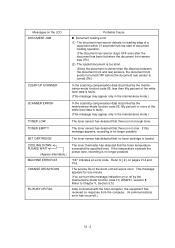
...document within 10 seconds from the computer. (A communications error has occurred.) VI - 2 COOLING DOWN PLEASE WAIT (Appear alternately.) MACHINE ERROR XX CHANGE DRUM SOON PC BUSY OR FAIL The toner thermister has detected that there is loaded. Refer to [ 2 ] on or off by the maintenance-mode ...has detected that the toner temperature exceeded the specified level. If this message indication on pages VI-4 and VI-5. This message appears for one minute. (You can turn this message appears, recording is faulty. (This message may appear only in the maintenance mode.) TONER LOW ...
...document within 10 seconds from the computer. (A communications error has occurred.) VI - 2 COOLING DOWN PLEASE WAIT (Appear alternately.) MACHINE ERROR XX CHANGE DRUM SOON PC BUSY OR FAIL The toner thermister has detected that there is loaded. Refer to [ 2 ] on or off by the maintenance-mode ...has detected that the toner temperature exceeded the specified level. If this message indication on pages VI-4 and VI-5. This message appears for one minute. (You can turn this message appears, recording is faulty. (This message may appear only in the maintenance mode.) TONER LOW ...

Service Manual
Page 154
... ADF and its related sections Scanner motor and its harness Document feed rollers and their related gears Main PCB ADF parts Multi-purpose sheet feeder Drum unit Heat-fixing unit Gear drive unit Main PCB VI - 15 Main PCB NCU PCB Check: [ 4 ] Paper/document feeding related Trouble (1) Neither "COPY: PRESS COPY...
... ADF and its related sections Scanner motor and its harness Document feed rollers and their related gears Main PCB ADF parts Multi-purpose sheet feeder Drum unit Heat-fixing unit Gear drive unit Main PCB VI - 15 Main PCB NCU PCB Check: [ 4 ] Paper/document feeding related Trouble (1) Neither "COPY: PRESS COPY...

Service Manual
Page 155
...CIS unit At the printer side Clean the high-voltage contacts for the grid and corona wire on the drum unit, main cover, and high-voltage power supply PCB. (Contacts and in the illustration given on the ... At the printer side Clean the high-voltage contacts for the developer roller on the drum unit, main cover, and high-voltage power supply PCB. (Contacts in the illustration given on page VI21)... Check the connection of the laser diode harness on page VI-21) Check the connection of the main-high-voltage flat cable. if...
...CIS unit At the printer side Clean the high-voltage contacts for the grid and corona wire on the drum unit, main cover, and high-voltage power supply PCB. (Contacts and in the illustration given on the ... At the printer side Clean the high-voltage contacts for the developer roller on the drum unit, main cover, and high-voltage power supply PCB. (Contacts in the illustration given on page VI21)... Check the connection of the laser diode harness on page VI-21) Check the connection of the main-high-voltage flat cable. if...

Service Manual
Page 156
... place, clean the toner sensor or replace the toner sensor PCB. CIS unit - Main PCB At the printer side Replace the toner cartridge with a new one and print 4 to the next step. Main PCB At the printer side Slide the wire cleaner tab to clean the corona wire inside the..., main cover, and high-voltage power supply PCB. (Contacts in the illustration given on page VI-21) Clean the grounding contacts on the drum unit, gear drive unit, and main cover. (Contacts and in the illustration given on page VI-21) Check the connection of the main-high-voltage ...
... place, clean the toner sensor or replace the toner sensor PCB. CIS unit - Main PCB At the printer side Replace the toner cartridge with a new one and print 4 to the next step. Main PCB At the printer side Slide the wire cleaner tab to clean the corona wire inside the..., main cover, and high-voltage power supply PCB. (Contacts in the illustration given on page VI-21) Clean the grounding contacts on the drum unit, gear drive unit, and main cover. (Contacts and in the illustration given on page VI-21) Check the connection of the main-high-voltage ...

Service Manual
Page 157
... power supply PCB. Make sure that the wire cleaner tab is returned to clean the corona wire inside the drum unit. If they appear at 94-mm or 17-mm intervals, replace the drum unit. At the printer side Check the connection of the main-high-voltage flat cable. VI - 18 Replace.... Slide the wire cleaner tab to its home position. CIS unit At the printer side Replace the drum unit. Replace the drum unit. Trouble (5) Black and blurred vertical stripes (6) Black and blurred horizontal stripes Action to be contaminated with toner. CIS unit At the printer side Clean ...
... power supply PCB. Make sure that the wire cleaner tab is returned to clean the corona wire inside the drum unit. If they appear at 94-mm or 17-mm intervals, replace the drum unit. At the printer side Check the connection of the main-high-voltage flat cable. VI - 18 Replace.... Slide the wire cleaner tab to its home position. CIS unit At the printer side Replace the drum unit. Replace the drum unit. Trouble (5) Black and blurred vertical stripes (6) Black and blurred horizontal stripes Action to be contaminated with toner. CIS unit At the printer side Clean ...

Service Manual
Page 159
At the printer side Replace the drum unit. At the printer side Instruct the user to use paper of paper (13) Poor fixing Action to back. Check that the equipment is placed on a flat surface. VI - 20 Shake the drum unit from left to right and front to be taken At the printer side Shake the toner cartridge. Replace the heat-fixing unit. Replace the heat-fixing unit. If the problem persists, replace it. Trouble (11) Blurred at either side (12) Dirt back of the recommended weight (less than 36 lb./m2).
At the printer side Replace the drum unit. At the printer side Instruct the user to use paper of paper (13) Poor fixing Action to back. Check that the equipment is placed on a flat surface. VI - 20 Shake the drum unit from left to right and front to be taken At the printer side Shake the toner cartridge. Replace the heat-fixing unit. Replace the heat-fixing unit. If the problem persists, replace it. Trouble (11) Blurred at either side (12) Dirt back of the recommended weight (less than 36 lb./m2).

Service Manual
Page 160
Location of High-voltage Contacts and Grounding Contacts Grounding Contacts High-voltage Contacts For transfer roller Gear drive unit Drum grounding board Drum unit For cleaner roller For grid For developer roller For corona wire High-voltage power supply PCB VI - 21
Location of High-voltage Contacts and Grounding Contacts Grounding Contacts High-voltage Contacts For transfer roller Gear drive unit Drum grounding board Drum unit For cleaner roller For grid For developer roller For corona wire High-voltage power supply PCB VI - 21


