Users Manual - English
Page 34
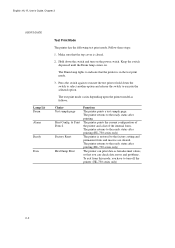
..., so that you have to indicate that the top cover is closed. 2. Make sure that the printer is restored to the ready status after printing.(HL-730 series only) The printer can check data errors and problems. To exit from this mode, you can print data as follows:... sample page Print Config & Print Fonts I Factory Reset Hex Dump Print Function The printer prints a test sample page. The Drum lamp lights to turn on . The printer prints the current configuration of the printer and a list of the internal fonts. The printer returns to execute the test print or hold down the...
..., so that you have to indicate that the top cover is closed. 2. Make sure that the printer is restored to the ready status after printing.(HL-730 series only) The printer can check data errors and problems. To exit from this mode, you can print data as follows:... sample page Print Config & Print Fonts I Factory Reset Hex Dump Print Function The printer prints a test sample page. The Drum lamp lights to turn on . The printer prints the current configuration of the printer and a list of the internal fonts. The printer returns to execute the test print or hold down the...

Users Manual - English
Page 49
Fig. 5-15 Installing the Drum Unit 8. Ejecting this chapter. 7. Install the new drum unit into the new drum unit. Close the top cover. 9. Starter Sheet Fig. 5-16 Ejecting the Starter Sheet 5-9 For more information, see "REPLACING THE TONER CARTRIDGE" in this sheet resets the drum life alarm. English: HL-YL User's Guide, Chapter 5 CHAPTER 5 MAINTENANCE 6. The printer can automatically ejects the starter sheet. Turn on the power switch. Install the toner cartridge into the printer.
Fig. 5-15 Installing the Drum Unit 8. Ejecting this chapter. 7. Install the new drum unit into the new drum unit. Close the top cover. 9. Starter Sheet Fig. 5-16 Ejecting the Starter Sheet 5-9 For more information, see "REPLACING THE TONER CARTRIDGE" in this sheet resets the drum life alarm. English: HL-YL User's Guide, Chapter 5 CHAPTER 5 MAINTENANCE 6. The printer can automatically ejects the starter sheet. Turn on the power switch. Install the toner cartridge into the printer.

Users Manual - English
Page 57
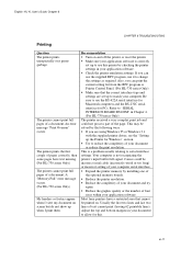
...HL-YL User's Guide, Chapter 6 CHAPTER 6 TROUBLESHOOTING CHAPTER 6 TROUBLESHOOTING ALARM INDICATIONS AT A GLANCE Operator Calls If a recoverable error occurs, the printer indicates an 'operator call' by blinking the Alarm lamp and any of printing left before the toner cartridge is empty. Load paper in the printer...cartridge with the panel switch as described below. Indicates that the printer has approximately 100 pages of the following lamps. The printer automatically recovers from most errors, but you may need to reset the printer with a new one referring to correct it. Find the ...
...HL-YL User's Guide, Chapter 6 CHAPTER 6 TROUBLESHOOTING CHAPTER 6 TROUBLESHOOTING ALARM INDICATIONS AT A GLANCE Operator Calls If a recoverable error occurs, the printer indicates an 'operator call' by blinking the Alarm lamp and any of printing left before the toner cartridge is empty. Load paper in the printer...cartridge with the panel switch as described below. Indicates that the printer has approximately 100 pages of the following lamps. The printer automatically recovers from most errors, but you may need to reset the printer with a new one referring to correct it. Find the ...
Users Manual - English
Page 67
...the number of your application software. This is a problem usually relating to use it prints garbage. Most laser printers have text missing. (For HL-730 series Only) The printer cannot print full pages of the page. Adjust the top and bottom margins in your application software. &#... incorrect setting of your computer serial interface. • Expand the printer memory by checking the printer settings in Chapter 4. (For HL-730 series Only) The printer received a very complex print job and could be printed on and off the printer or reset the printer. • Make sure your computer.
...the number of your application software. This is a problem usually relating to use it prints garbage. Most laser printers have text missing. (For HL-730 series Only) The printer cannot print full pages of the page. Adjust the top and bottom margins in your application software. &#... incorrect setting of your computer serial interface. • Expand the printer memory by checking the printer settings in Chapter 4. (For HL-730 series Only) The printer received a very complex print job and could be printed on and off the printer or reset the printer. • Make sure your computer.
Quick Setup Guide - English
Page 14
... works only in the environment where your printer is recommended that you can change further printer settings, such as Print Form, Self Print, Reset Printer, Sleep Control. Alt + C You can monitor the printer status on a network. F1 You can directly control printer functions such as , margin settings, continue... F1. English: HL-YL Quick Setup Guide, Body Additionally, there are four sub-menus as a TSR program. 13 t The program does not work in your computer, you completely exit from your computer memory. Alt + G You can suspend the Printer Status monitor with ...
... works only in the environment where your printer is recommended that you can change further printer settings, such as Print Form, Self Print, Reset Printer, Sleep Control. Alt + C You can monitor the printer status on a network. F1 You can directly control printer functions such as , margin settings, continue... F1. English: HL-YL Quick Setup Guide, Body Additionally, there are four sub-menus as a TSR program. 13 t The program does not work in your computer, you completely exit from your computer memory. Alt + G You can suspend the Printer Status monitor with ...

Service Manual
Page 4
...Core ...II-5 1.3.2 ASIC ...II-7 1.3.3 ROM ...II-13 1.3.4 DRAM...II-13 1.3.5 Optional RAM ...II-15 1.3.6 Optional Serial I/O ...II-16 1.3.7 EEPROM ...II-16 1.3.8 Reset Circuit...II-17 1.3.9 CDCC I/O ...II-18 1.3.10 Engine I -1 3. SPECIFICATIONS ...I-4 3.1 Printing...I-4 3.2 Functions ...I-5 3.3 Electrical and Mechanical ...I-6 3.4 Paper Specification ...I-7 3.5 Print ... CHAPTER I FEATURES AND SPECIFICATIONS I -11 CHAPTER II THEORY OF OPERATION II-1 1. SAFETY INFORMATION I-10 4.1 Laser Safety (110 - 120V Model only I-10 4.2 CDRH Regulations (110 -120V Model only I-10 4.3 Caution for...
...Core ...II-5 1.3.2 ASIC ...II-7 1.3.3 ROM ...II-13 1.3.4 DRAM...II-13 1.3.5 Optional RAM ...II-15 1.3.6 Optional Serial I/O ...II-16 1.3.7 EEPROM ...II-16 1.3.8 Reset Circuit...II-17 1.3.9 CDCC I/O ...II-18 1.3.10 Engine I -1 3. SPECIFICATIONS ...I-4 3.1 Printing...I-4 3.2 Functions ...I-5 3.3 Electrical and Mechanical ...I-6 3.4 Paper Specification ...I-7 3.5 Print ... CHAPTER I FEATURES AND SPECIFICATIONS I -11 CHAPTER II THEORY OF OPERATION II-1 1. SAFETY INFORMATION I-10 4.1 Laser Safety (110 - 120V Model only I-10 4.2 CDRH Regulations (110 -120V Model only I-10 4.3 Caution for...

Service Manual
Page 20
ASIC Reset Circuit CPU Core (Z80) BUS INT DRAM 0.5 Mbytes Option RAM 1.5 Mbytes or 3.5 Mbytes DRAM Control EEPROM (128 x 8 bits) Motor Driver To Panel sensor PCB Fig. 2.3 II-3 Oscillator (12.27 MHz) Program ROM 16 Kbytes Working S-RAM 512 Bytes Timer CDCC Parallel I/O To PC DATA Extension FIFO EEPROM I/O Engine Control I/O 1.2 Main PCB Block Diagram Fig. 2.3 shows a block diagram of the main PCB.
ASIC Reset Circuit CPU Core (Z80) BUS INT DRAM 0.5 Mbytes Option RAM 1.5 Mbytes or 3.5 Mbytes DRAM Control EEPROM (128 x 8 bits) Motor Driver To Panel sensor PCB Fig. 2.3 II-3 Oscillator (12.27 MHz) Program ROM 16 Kbytes Working S-RAM 512 Bytes Timer CDCC Parallel I/O To PC DATA Extension FIFO EEPROM I/O Engine Control I/O 1.2 Main PCB Block Diagram Fig. 2.3 shows a block diagram of the main PCB.

Service Manual
Page 21
Fig. 2.4 shows a block diagram of the main PCB. Reset Circuit CPU Core (MC68EC000) BUS INT Program + Font ROM 512 Kbytes RAM (0.5 Mbytes) Option RAM (1M or 1.5Mbytes) Option Serial I/O (RS232C & RS422A) EEPROM (128 8 bits) Motor Driver To Panel Sensor PCB Fig. 2.4 A S I C Oscillator (15.3MHz) Address Decoder DRAM Control Timer FIFO DATA EXTENSION CDCC Parallel I/O To PC Soft Support EEPROM I/O Engine Control I/O II-4
Fig. 2.4 shows a block diagram of the main PCB. Reset Circuit CPU Core (MC68EC000) BUS INT Program + Font ROM 512 Kbytes RAM (0.5 Mbytes) Option RAM (1M or 1.5Mbytes) Option Serial I/O (RS232C & RS422A) EEPROM (128 8 bits) Motor Driver To Panel Sensor PCB Fig. 2.4 A S I C Oscillator (15.3MHz) Address Decoder DRAM Control Timer FIFO DATA EXTENSION CDCC Parallel I/O To PC Soft Support EEPROM I/O Engine Control I/O II-4

Service Manual
Page 34
Fig. 2.18 II-17 The reset voltage is 4.2V (typ.) and the LOW period of reset is 200 ms (typ). Fig. 2.17 The reset IC is PST591DMT. The reset voltage is 4.2V (typ.) and the LOW period of reset is 50 ms (typ.). 1.3.8 Reset Circuit The reset IC is PST593DMT.
Fig. 2.18 II-17 The reset voltage is 4.2V (typ.) and the LOW period of reset is 200 ms (typ). Fig. 2.17 The reset IC is PST591DMT. The reset voltage is 4.2V (typ.) and the LOW period of reset is 50 ms (typ.). 1.3.8 Reset Circuit The reset IC is PST593DMT.

Service Manual
Page 96
...) 2.4.1 Photosensitive Drum Refer to HL-730 (P.II-28) 2.4.2 Primary Charger Refer to HL-730 (P.II-28) 2.4.3 Developer Roller Refer to HL-730 (P.II-28) 2.4.4 Transfer Roller Refer to HL-730 (P.I-11) CHAPTER II THEORY OF OPERATION II-1 1. SAFETY INFORMATION REFER TO HL-730 (P.I-10) 3.1 Laser Safety (110 - 120V Model only Refer to HL-730 (P.I-10) 3.2 CDRH Regulations...
...) 2.4.1 Photosensitive Drum Refer to HL-730 (P.II-28) 2.4.2 Primary Charger Refer to HL-730 (P.II-28) 2.4.3 Developer Roller Refer to HL-730 (P.II-28) 2.4.4 Transfer Roller Refer to HL-730 (P.I-11) CHAPTER II THEORY OF OPERATION II-1 1. SAFETY INFORMATION REFER TO HL-730 (P.I-10) 3.1 Laser Safety (110 - 120V Model only Refer to HL-730 (P.I-10) 3.2 CDRH Regulations...

Service Manual
Page 113
Fig. 2.10 1.3.9 CDCC I/O Fig. 2.11 shows the CDCC interface circuit. Fig. 2.11 II-11 1.3.8 Reset Circuit The reset IC is 50 ms (typ). The reset voltage is 4.2V (typ.) and the LOW period of reset is PST591DMT.
Fig. 2.10 1.3.9 CDCC I/O Fig. 2.11 shows the CDCC interface circuit. Fig. 2.11 II-11 1.3.8 Reset Circuit The reset IC is 50 ms (typ). The reset voltage is 4.2V (typ.) and the LOW period of reset is PST591DMT.


