
Users Manual - English
Page 34
... position until the printer automatically feeds it in for a short distance, and then let go of the printer, open the face-up output tray to reset the two blue tabs back to their original position. Figure 1-32 5 Using both hands put the envelope in the figure below).
... position until the printer automatically feeds it in for a short distance, and then let go of the printer, open the face-up output tray to reset the two blue tabs back to their original position. Figure 1-32 5 Using both hands put the envelope in the figure below).

Users Manual - English
Page 38
... back of the tray and remain under the maximum paper height guides on both sides of the printer, open the face-up output tray to reset the two blue tabs back to their original position. Figure 1-37 5 Put envelopes in the MP tray so that the envelopes are not, the envelopes...
... back of the tray and remain under the maximum paper height guides on both sides of the printer, open the face-up output tray to reset the two blue tabs back to their original position. Figure 1-37 5 Put envelopes in the MP tray so that the envelopes are not, the envelopes...
Users Manual - English
Page 53
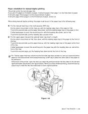
... first, face down, with the leading edge (top) of the paper in first. If you have finished printing, close the face-up output tray to reset the two blue tabs back to their original position. When doing manual duplex printing, the paper must be put the paper face up , and at...
... first, face down, with the leading edge (top) of the paper in first. If you have finished printing, close the face-up output tray to reset the two blue tabs back to their original position. When doing manual duplex printing, the paper must be put the paper face up , and at...
Users Manual - English
Page 87
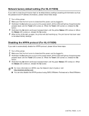
... the Go button and keep it pressed down until the yellow Status LED comes on APIPA, see the Network User's Guide or visit http://solutions.brother.com ■ You can also disable the APIPA protocol using EWS, BRAdmin Professional or Web BRAdmin. CONTROL PANEL 3 - 11 When the Toner LED...Go button as you turn on the power switch. The print server has been reset to its default factory settings (resetting all the LEDs light up again, the printer will light up. Disabling the APIPA protocol (For HL-5170DN) If you wish to automatically disable the APIPA protocol, please follow these ...
... the Go button and keep it pressed down until the yellow Status LED comes on APIPA, see the Network User's Guide or visit http://solutions.brother.com ■ You can also disable the APIPA protocol using EWS, BRAdmin Professional or Web BRAdmin. CONTROL PANEL 3 - 11 When the Toner LED...Go button as you turn on the power switch. The print server has been reset to its default factory settings (resetting all the LEDs light up again, the printer will light up. Disabling the APIPA protocol (For HL-5170DN) If you wish to automatically disable the APIPA protocol, please follow these ...
Users Manual - English
Page 103
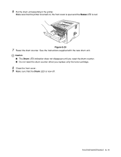
See the instructions supplied with the new drum unit. Caution ■ The Drum LED indication does not disappear until you reset the drum counter. ■ Do not reset the drum counter when you replace only the toner cartridge. 8 Close the front cover. 9 Make sure that the printer is turned on, the front cover is open and the Status LED is now off. Figure 5-20 7 Reset the drum counter. ROUTINE MAINTENANCE 5 - 11 Make sure that the Drum LED is red. 6 Put the drum unit assembly in the printer.
See the instructions supplied with the new drum unit. Caution ■ The Drum LED indication does not disappear until you reset the drum counter. ■ Do not reset the drum counter when you replace only the toner cartridge. 8 Close the front cover. 9 Make sure that the printer is turned on, the front cover is open and the Status LED is now off. Figure 5-20 7 Reset the drum counter. ROUTINE MAINTENANCE 5 - 11 Make sure that the Drum LED is red. 6 Put the drum unit assembly in the printer.

Users Manual - English
Page 121
Examples of poor print quality Recommendation ■ Open the face-up output tray to reset the two blue tabs back to their original position. ABCDEFG EFGHIJKLMN Envelope creases TROUBLESHOOTING 6 - 16 When you have finished printing your envelopes, close the face-up (back) output tray and push down the blue tabs at the left and right hand sides (as shown in the figure below). See page 1-31.
Examples of poor print quality Recommendation ■ Open the face-up output tray to reset the two blue tabs back to their original position. ABCDEFG EFGHIJKLMN Envelope creases TROUBLESHOOTING 6 - 16 When you have finished printing your envelopes, close the face-up (back) output tray and push down the blue tabs at the left and right hand sides (as shown in the figure below). See page 1-31.

Service Manual
Page 5
...1.3 Main PCB ...3-3 1.3.1 CPU ...3-3 1.3.2 USB...3-5 1.3.3 IEEE 1284...3-6 1.3.4 Network Interface ...3-7 1.3.5 ROM...3-8 1.3.6 Flash ROM...3-9 1.3.7 SDRAM ...3-10 1.3.8 Optional RAM...3-11 1.3.9 EEPROM ...3-13 1.3.10 Reset Circuit ...3-13 1.3.11 Engine I/O ...3-14 1.3.12 Panel I/O ...3-14 1.3.13 Video I/O ...3-15 1.3.14 Power Supply ...3-16 1.4 Engine PCB...3-17 1.5 Power Supply ...3-18 1.5.1 Low-voltage Power... 5.5 Other Control Features 2-33 5.5.1 Sleep mode...2-33 5.5.2 Print a test page ...2-34 5.5.3 Print Settings...2-34 5.5.4 Print fonts (For HL-5140, HL-5150D and HL-5170DN 2-35 6.
...1.3 Main PCB ...3-3 1.3.1 CPU ...3-3 1.3.2 USB...3-5 1.3.3 IEEE 1284...3-6 1.3.4 Network Interface ...3-7 1.3.5 ROM...3-8 1.3.6 Flash ROM...3-9 1.3.7 SDRAM ...3-10 1.3.8 Optional RAM...3-11 1.3.9 EEPROM ...3-13 1.3.10 Reset Circuit ...3-13 1.3.11 Engine I/O ...3-14 1.3.12 Panel I/O ...3-14 1.3.13 Video I/O ...3-15 1.3.14 Power Supply ...3-16 1.4 Engine PCB...3-17 1.5 Power Supply ...3-18 1.5.1 Low-voltage Power... 5.5 Other Control Features 2-33 5.5.1 Sleep mode...2-33 5.5.2 Print a test page ...2-34 5.5.3 Print Settings...2-34 5.5.4 Print fonts (For HL-5140, HL-5150D and HL-5170DN 2-35 6.

Service Manual
Page 51
NOTE: A NO PAPER status is shown by the control panel LEDs until you have finished printing your envelopes, close the back output tray to reset the two blue tabs back to their original position. Fig.2-17 (4) Open the manual feed tray. Fig. 2-18 NOTE: At the back of paper in ...
NOTE: A NO PAPER status is shown by the control panel LEDs until you have finished printing your envelopes, close the back output tray to reset the two blue tabs back to their original position. Fig.2-17 (4) Open the manual feed tray. Fig. 2-18 NOTE: At the back of paper in ...

Service Manual
Page 53
... not be fed properly, resulting in the MP tray. Fig.2-25 2-20 When you have finished printing your envelopes, close the back output tray to reset the two blue tabs back to the Basic tab, select Paper Size and then select DL Long Edge.
... not be fed properly, resulting in the MP tray. Fig.2-25 2-20 When you have finished printing your envelopes, close the back output tray to reset the two blue tabs back to the Basic tab, select Paper Size and then select DL Long Edge.

Service Manual
Page 59
... edge (top) of the paper in first. CHAPTER 2 INSTALLATION AND BASIC OPERATION (4) Repeat Step 3 until you have finished printing, close the back output tray to reset the two blue tabs back to their original position. If you print 10 pages on 5 sheets of paper, it will print page 6 then page 5 on...
... edge (top) of the paper in first. CHAPTER 2 INSTALLATION AND BASIC OPERATION (4) Repeat Step 3 until you have finished printing, close the back output tray to reset the two blue tabs back to their original position. If you print 10 pages on 5 sheets of paper, it will print page 6 then page 5 on...

Service Manual
Page 69
...however, hold down the Go button as the password and IP address information), please follow steps 1 to reset the printer and automatically disable the APIPA protocol, follow these steps; (1) Turn off . NETWORK FUNCTIONS (FOR HL-5170DN) 6.1 LED functions Link/Speed LED Active LED Fig. 2-47 No light: If both of the...plugged in. (3) Hold down the Go button until the yellow Status LED comes on APIPA, see the Network User's Guide or visit http://solutions.brother.com 2-36 This Link/Speed LED will light up . All the LEDs will be orange if the print server is not connected to its ...
...however, hold down the Go button as the password and IP address information), please follow steps 1 to reset the printer and automatically disable the APIPA protocol, follow these steps; (1) Turn off . NETWORK FUNCTIONS (FOR HL-5170DN) 6.1 LED functions Link/Speed LED Active LED Fig. 2-47 No light: If both of the...plugged in. (3) Hold down the Go button until the yellow Status LED comes on APIPA, see the Network User's Guide or visit http://solutions.brother.com 2-36 This Link/Speed LED will light up . All the LEDs will be orange if the print server is not connected to its ...

Service Manual
Page 72
.... (HL-5130/5140/5150D/5170DN) A S I C Reset Circuit CPU Core (SPARClite 133MHz) BUS INT Oscillator 66.6MHz Program + Font ROM HL-5130:2MB HL-5140:4MB HL-5150D/5170DN:8MB Network Program (HL-5170DN only)(1.5 MB) STRAGE (0.5 MB) RAM HL-5130:8MB HL-5140/5150D:16MB HL-5170DN:32MB RAM (DIMM) (max. 128MB) Option for HL-5140/5150D/5170DN EEPROM HL-5130/5140/5150D:512 x 8 bit HL-5170DN...
.... (HL-5130/5140/5150D/5170DN) A S I C Reset Circuit CPU Core (SPARClite 133MHz) BUS INT Oscillator 66.6MHz Program + Font ROM HL-5130:2MB HL-5140:4MB HL-5150D/5170DN:8MB Network Program (HL-5170DN only)(1.5 MB) STRAGE (0.5 MB) RAM HL-5130:8MB HL-5140/5150D:16MB HL-5170DN:32MB RAM (DIMM) (max. 128MB) Option for HL-5140/5150D/5170DN EEPROM HL-5130/5140/5150D:512 x 8 bit HL-5170DN...

Service Manual
Page 78
... THEORY OF OPERATION 1.3.5 ROM A 16Mbit ROM (x 16bit) is fitted. (HL-5130) A 32Mbit ROM (x 16bit) is fitted. (HL-5140) A 64Mbit ROM (x 16bit) is fitted. (HL-5150D) FLASH PIN PIN TOSHIBA FUJITSU FUJITSU LV type DL type Mirror 64M 64M ...37 CE VCC VDD3 WE 27 OE VSS-27 46 RY/BY VSS-46 C79 C103 0V BYTE R83 0 RESET TP50 13 R80 0 NC A0 14 A1 WR/ACC VDD3 A2 A3 29 A4 DQ0 31 A5 DQ1 ...R101 0 @U10 CE 37 VCC VDD3 WE 27 OE VSS-27 46 RY/BY VSS-46 C110 C103 0V BYTE RESET @R109 0 TP50 13 @R108 0 NC A0 14 A1 WR/ACC VDD3 A2 A3 29 A4 DQ0 31 A5...
... THEORY OF OPERATION 1.3.5 ROM A 16Mbit ROM (x 16bit) is fitted. (HL-5130) A 32Mbit ROM (x 16bit) is fitted. (HL-5140) A 64Mbit ROM (x 16bit) is fitted. (HL-5150D) FLASH PIN PIN TOSHIBA FUJITSU FUJITSU LV type DL type Mirror 64M 64M ...37 CE VCC VDD3 WE 27 OE VSS-27 46 RY/BY VSS-46 C79 C103 0V BYTE R83 0 RESET TP50 13 R80 0 NC A0 14 A1 WR/ACC VDD3 A2 A3 29 A4 DQ0 31 A5 DQ1 ...R101 0 @U10 CE 37 VCC VDD3 WE 27 OE VSS-27 46 RY/BY VSS-46 C110 C103 0V BYTE RESET @R109 0 TP50 13 @R108 0 NC A0 14 A1 WR/ACC VDD3 A2 A3 29 A4 DQ0 31 A5...

Service Manual
Page 79
HL-5130/5140/5150D/5170DN SERVICE MANUAL 1.3.6 Flash ROM A 16Mbit flash ROM (x 16bit) is fitted. (HL-5170DN) FLASH PIN PIN 9 13 14 15 47 FUJITSU TOSHIBA 64M 32M 16M 8M 64M A21 A19 A19 NC A19 ACC NC NC NC A21 ... TP150 @R136 9 ADR[21] 0 10 ADR[22] @R135 0 U12 37 CE VCC VDD3 WE OE RY/BY 27 VSS27 46 VSS46 @C134 C103 0V BYTE RESET A0 A1 NC13 @R133 0 TP152 13 @R134 0 14 NC14 VDD3 A2 A3 29 A4 DQ0 31 A5 DQ1 33 A6 DQ2 35 A7 DQ3 38...
HL-5130/5140/5150D/5170DN SERVICE MANUAL 1.3.6 Flash ROM A 16Mbit flash ROM (x 16bit) is fitted. (HL-5170DN) FLASH PIN PIN 9 13 14 15 47 FUJITSU TOSHIBA 64M 32M 16M 8M 64M A21 A19 A19 NC A19 ACC NC NC NC A21 ... TP150 @R136 9 ADR[21] 0 10 ADR[22] @R135 0 U12 37 CE VCC VDD3 WE OE RY/BY 27 VSS27 46 VSS46 @C134 C103 0V BYTE RESET A0 A1 NC13 @R133 0 TP152 13 @R134 0 14 NC14 VDD3 A2 A3 29 A4 DQ0 31 A5 DQ1 33 A6 DQ2 35 A7 DQ3 38...

Service Manual
Page 83
... SDA 2 A1 7 TEST 3 A2 C68 C103 VDD3 0V Aurora M24C64-WMN6 0V Fig. 3-18 1.3.10 Reset Circuit The reset IC is BR24C04 type of two-wire method with a 512 x 8bit configuration. HL-5130/5140/5150D/5170DN SERVICE MANUAL 1.3.9 EEPROM The EEPROM is a R3112N281C. U5 EESCL EESDA VDD3 TP58 203 R32 TP59 202... VCC 6 SCL 4 VSS 1 A0 5 SDA 7 TEST 2 A1 3 A2 BR24C04F C31 C103 0V VDD3 0V Fig. 3-17 The EEPROM is 22.4ms (typ.) < HL-5130/5140/5150D > VDD3 C33 C40 U3 5 CD C103 4 TP310 NC C103 2 VCC 3 1 0V GND VOUT R3112N281C TP4 R43 68 C43 0V C101 Fig. 3-19 VDD3 C71...
... SDA 2 A1 7 TEST 3 A2 C68 C103 VDD3 0V Aurora M24C64-WMN6 0V Fig. 3-18 1.3.10 Reset Circuit The reset IC is BR24C04 type of two-wire method with a 512 x 8bit configuration. HL-5130/5140/5150D/5170DN SERVICE MANUAL 1.3.9 EEPROM The EEPROM is a R3112N281C. U5 EESCL EESDA VDD3 TP58 203 R32 TP59 202... VCC 6 SCL 4 VSS 1 A0 5 SDA 7 TEST 2 A1 3 A2 BR24C04F C31 C103 0V VDD3 0V Fig. 3-17 The EEPROM is 22.4ms (typ.) < HL-5130/5140/5150D > VDD3 C33 C40 U3 5 CD C103 4 TP310 NC C103 2 VCC 3 1 0V GND VOUT R3112N281C TP4 R43 68 C43 0V C101 Fig. 3-19 VDD3 C71...

Service Manual
Page 84
... ENGRSTN 255 ENGDO TP200 VDD3 R104 1k TP201 R100 100 ENGDI 2D VDD5 VDD3 R101 4.7k TP202 TP203 TP204 R103 100 TP205 ENGINE CN8 1 3.3V 5 RESET 3 TXD 4 RXD 6 5V R102 4.7k C106 C102 C119 C103 C101 C105 C101 C103 Aurora 0V Fig. 3-21 C117 C118 2 0V B6B-PH-K-S U7 ENGDI 3D... VDD3 R142 1k R138 100 ENGDI 1D VDD5 TP202 TP203 TP204 R141 100 R139 4.7k VDD3 L10 L14 L12 TP205 L13 L15 ENGINE CN9 0 1 3.3V 0 5 RESET 0 3 TXD 0 4 RXD 0 6 5V C143 C102 R140 4.7k C154 C103 C103 C101 C101 C152 C153 C142 0V Fig. 3-22 L11 0 2 0V B6B-PH-K-S 1.3.12 Panel I /O The...
... ENGRSTN 255 ENGDO TP200 VDD3 R104 1k TP201 R100 100 ENGDI 2D VDD5 VDD3 R101 4.7k TP202 TP203 TP204 R103 100 TP205 ENGINE CN8 1 3.3V 5 RESET 3 TXD 4 RXD 6 5V R102 4.7k C106 C102 C119 C103 C101 C105 C101 C103 Aurora 0V Fig. 3-21 C117 C118 2 0V B6B-PH-K-S U7 ENGDI 3D... VDD3 R142 1k R138 100 ENGDI 1D VDD5 TP202 TP203 TP204 R141 100 R139 4.7k VDD3 L10 L14 L12 TP205 L13 L15 ENGINE CN9 0 1 3.3V 0 5 RESET 0 3 TXD 0 4 RXD 0 6 5V C143 C102 R140 4.7k C154 C103 C103 C101 C101 C152 C153 C142 0V Fig. 3-22 L11 0 2 0V B6B-PH-K-S 1.3.12 Panel I /O The...

Service Manual
Page 174
... assembly. Refer to subsection 3. 'PERIODICAL CLEANING' in the printer. Make sure that toner powder does not spill out of the drum unit assembly. (Fig.5-4) HL-5130/5140/5150D/5170DN SERVICE MANUAL (4) Unpack the new drum unit. (5) Put the toner cartridge in the new drum unit until you hear it separate from the... pick up the drum unit tightly so that the printer is turned on, the front cover is open and the Status LED is red. (7) To reset the drum counter, press and hold down the Go button until all four LEDs are lit. (3) While pressing the blue lock lever, take the toner...
... assembly. Refer to subsection 3. 'PERIODICAL CLEANING' in the printer. Make sure that toner powder does not spill out of the drum unit assembly. (Fig.5-4) HL-5130/5140/5150D/5170DN SERVICE MANUAL (4) Unpack the new drum unit. (5) Put the toner cartridge in the new drum unit until you hear it separate from the... pick up the drum unit tightly so that the printer is turned on, the front cover is open and the Status LED is red. (7) To reset the drum counter, press and hold down the Go button until all four LEDs are lit. (3) While pressing the blue lock lever, take the toner...

Service Manual
Page 192
Clear the jammed paper inside the printer. Press the go button. (Error message is displayed. (Except for each indication to reset the printer with a new one. Load paper into the printer. The printer automatically recovers from most errors, but it may also be fed from the ... unit. Close the jam clear cover of error Toner empty Cover open (Front cover) Cover open (Jam clear cover) Paper jam No paper (HL-5130) No paper (HL5140/5150D/5170 DN) No tray 1 Manual feed Memory full Print overrun Clean drum unit Toner (Yellow light) LED Drum (Yellow light) Paper (Yellow blink...
Clear the jammed paper inside the printer. Press the go button. (Error message is displayed. (Except for each indication to reset the printer with a new one. Load paper into the printer. The printer automatically recovers from most errors, but it may also be fed from the ... unit. Close the jam clear cover of error Toner empty Cover open (Front cover) Cover open (Jam clear cover) Paper jam No paper (HL-5130) No paper (HL5140/5150D/5170 DN) No tray 1 Manual feed Memory full Print overrun Clean drum unit Toner (Yellow light) LED Drum (Yellow light) Paper (Yellow blink...

Service Manual
Page 205
... the specified system environment. Check also that the appropriate printer driver is also connected to the correct interface connectors of 1.3. 'INSPECTION MODE' in Chapter 7. (7) Try resetting the factory settings. HL-5130/5140/5150D/5170DN SERVICE MANUAL 5.
... the specified system environment. Check also that the appropriate printer driver is also connected to the correct interface connectors of 1.3. 'INSPECTION MODE' in Chapter 7. (7) Try resetting the factory settings. HL-5130/5140/5150D/5170DN SERVICE MANUAL 5.

Service Manual
Page 234
... not damaged or broken. For details on the PC screen, follow the procedures below in the event of less than 2 meters (6.6 feet) in Chapter 7. (8) Try resetting the factory settings. Check also that the correct print port is set as Default'. P-1 The printer prints unexpectedly or it possible to the printer only...
... not damaged or broken. For details on the PC screen, follow the procedures below in the event of less than 2 meters (6.6 feet) in Chapter 7. (8) Try resetting the factory settings. Check also that the correct print port is set as Default'. P-1 The printer prints unexpectedly or it possible to the printer only...


