
Users Manual - English
Page 174
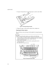
... to inhale the toner. Cleaning the Printer Interior Dip a soft cloth in water and wring it will not come out. • Never touch the hot fuser. • Never touch or clean the transfer roller, or print quality may be adversely affected. • Be careful not to the following: • If your...
... to inhale the toner. Cleaning the Printer Interior Dip a soft cloth in water and wring it will not come out. • Never touch the hot fuser. • Never touch or clean the transfer roller, or print quality may be adversely affected. • Be careful not to the following: • If your...
Users Manual - English
Page 180
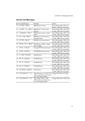
.... 51 LASER BD MALF Malfunction of fan motor in Turn off the printer. CHAPTER 7 TROUBLESHOOTING Service Call Messages Service Call Message Meaning Action 50 FUSER MALF Malfunction of high voltage Turn off the printer. Wait a few seconds, then turn it on again. 66 NV-W ERROR NV-RAM error ... DX FAN MALF Malfunction of laser beam Turn off the printer. Wait a few seconds, then turn it on again. 55 HIGH VOL MALF Malfunction of fuser Turn off the printer. Wait a few seconds, then turn it on again. 63 D-RAM ERROR D-RAM error Turn off the printer. Wait a few...
.... 51 LASER BD MALF Malfunction of fan motor in Turn off the printer. CHAPTER 7 TROUBLESHOOTING Service Call Messages Service Call Message Meaning Action 50 FUSER MALF Malfunction of high voltage Turn off the printer. Wait a few seconds, then turn it on again. 66 NV-W ERROR NV-RAM error ... DX FAN MALF Malfunction of laser beam Turn off the printer. Wait a few seconds, then turn it on again. 55 HIGH VOL MALF Malfunction of fuser Turn off the printer. Wait a few seconds, then turn it on again. 63 D-RAM ERROR D-RAM error Turn off the printer. Wait a few...
Users Manual - English
Page 269
... size: 4-53, 4-57 font source: 4-51, 4-55 font style: 4-52, 4-56 FONT switch: 4-49 form feed: 4-61 form feed suppress: 4-43 FORM FEED switch: 4-61 fuser: 6-6 G G3/G4: 1-8 G3/G4 format: Appendix-49 graphics mode: 4-26 H HDD card: 1-10, 5-2 hex dump mode: 4-88 high resolution control (HRC): 1-4, 4-30 high speed parallel...
... size: 4-53, 4-57 font source: 4-51, 4-55 font style: 4-52, 4-56 FONT switch: 4-49 form feed: 4-61 form feed suppress: 4-43 FORM FEED switch: 4-61 fuser: 6-6 G G3/G4: 1-8 G3/G4 format: Appendix-49 graphics mode: 4-26 H HDD card: 1-10, 5-2 hex dump mode: 4-88 high resolution control (HRC): 1-4, 4-30 high speed parallel...

Service Manual
Page 38
... R93 1 1 R101 D7 CP5 C105 R100 R99 SP9 C107 R94 52 R86 C117 53 /RESET Q18 R82 R80 FAN Q16 3 Q19 Q17 D6 D5 P11 FUSER 1 1 4 C81 C80 R60 R61 D4 C83 R59 R58 C100 R81 R56 C87 R125 C102 C99 R74 R77 R85 C97 C88 32 1 R66 33 208 C89...
... R93 1 1 R101 D7 CP5 C105 R100 R99 SP9 C107 R94 52 R86 C117 53 /RESET Q18 R82 R80 FAN Q16 3 Q19 Q17 D6 D5 P11 FUSER 1 1 4 C81 C80 R60 R61 D4 C83 R59 R58 C100 R81 R56 C87 R125 C102 C99 R74 R77 R85 C97 C88 32 1 R66 33 208 C89...

Service Manual
Page 39
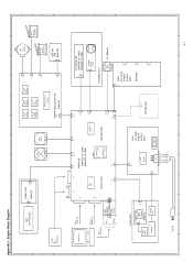
Fuser Unit Control C-1. Scanner Motor Control Circuit G-2. Cover Open Detect Circuit K. Paper Feeder PCB Control Signals and Connector E. Scanner Unit Control G-1. Main Motor Control Circuit J. Engine ...
Fuser Unit Control C-1. Scanner Motor Control Circuit G-2. Cover Open Detect Circuit K. Paper Feeder PCB Control Signals and Connector E. Scanner Unit Control G-1. Main Motor Control Circuit J. Engine ...

Service Manual
Page 55
PCB holder Screws Figure 4.12 (4) Remove the switch flat cable 21P and the feed flat cable 20P. (5) Remove the fan harness 3P, the fuser harness 4P, the SCN harness 4P, the SCN flat cable 6P, the DC motor harness 4P, the HV harness 16P and the LV harness 8P. ... flat cable 21P Main PCB assy Figure 4.14 IV - 7 SCN harness 4P DC motor harness 4P HV harness 16P LV harness 8P Fan harness 3P Fuser harness 4P SCN flat cable 6P Feed flat cable 20P (6) Remove the main PCB assy. (3) Remove the PCB holder by loosening PCB holder fixing screws...
PCB holder Screws Figure 4.12 (4) Remove the switch flat cable 21P and the feed flat cable 20P. (5) Remove the fan harness 3P, the fuser harness 4P, the SCN harness 4P, the SCN flat cable 6P, the DC motor harness 4P, the HV harness 16P and the LV harness 8P. ... flat cable 21P Main PCB assy Figure 4.14 IV - 7 SCN harness 4P DC motor harness 4P HV harness 16P LV harness 8P Fan harness 3P Fuser harness 4P SCN flat cable 6P Feed flat cable 20P (6) Remove the main PCB assy. (3) Remove the PCB holder by loosening PCB holder fixing screws...

Service Manual
Page 77
... may be used 4 Lubricating oil (Moly kote EM-30L) For drive mechanism • Tool No. 4. keep away from flame 3 Lubricating oil (silicon grease KS64F) For fuser • Tool No. LIST OF LUBRICANTS AND CLEANERS Table 5.3 No. Material name Components Use 1 Alcohol ethyl (pure C2H5OH, (CH3)2 or denatured) or CHOH isopropyl (pure...
... may be used 4 Lubricating oil (Moly kote EM-30L) For drive mechanism • Tool No. 4. keep away from flame 3 Lubricating oil (silicon grease KS64F) For fuser • Tool No. LIST OF LUBRICANTS AND CLEANERS Table 5.3 No. Material name Components Use 1 Alcohol ethyl (pure C2H5OH, (CH3)2 or denatured) or CHOH isopropyl (pure...

Service Manual
Page 91
... cause Step Check Result Remedy Actuator 1 Does the actuator of the high-voltage power supply PCB assy dirty? Fuser harness 3 Does the voltage of P11-1 in the main PCB No Replace the fuser harness Feed flat cable connector rise from 0V to 5V when the registration sensor is covered, or the voltage...
... cause Step Check Result Remedy Actuator 1 Does the actuator of the high-voltage power supply PCB assy dirty? Fuser harness 3 Does the voltage of P11-1 in the main PCB No Replace the fuser harness Feed flat cable connector rise from 0V to 5V when the registration sensor is covered, or the voltage...

Service Manual
Page 94
... is installed in the fixing unit conductive? the SCN harness 4P, SCN flat Scanner unit cable 6P or the scanner unit. VI - 17 M-14 "50 FUSER MALF" is switched on, does the voltage at connector pin P4-1 on the main PCB go from 5V to prevent the fixing the unit from...
... is installed in the fixing unit conductive? the SCN harness 4P, SCN flat Scanner unit cable 6P or the scanner unit. VI - 17 M-14 "50 FUSER MALF" is switched on, does the voltage at connector pin P4-1 on the main PCB go from 5V to prevent the fixing the unit from...

Service Manual
Page 106
Table 6.4 Service Call Messages Service Call Message 50 FUSER MALF 51 LASER BD MALF 52 SCANNER MALF 53 DX FAN MALF 54 MOTOR MALF 55 HIGH VOL MALF 61 PROG ERROR 62 FONT ERROR ...63 D-RAM ERROR 66 NV-W ERROR 67 NV-R ERROR 68 NV-B ERROR 60 SYSTEM ERROR XXXXX Meaning Malfunction of fuser Malfunction of laser beam detector Malfunction of laser scanner motor Malfunction of highvoltage power supply Program ROM checksum error Font ROM checksum error D-RAM error...
Table 6.4 Service Call Messages Service Call Message 50 FUSER MALF 51 LASER BD MALF 52 SCANNER MALF 53 DX FAN MALF 54 MOTOR MALF 55 HIGH VOL MALF 61 PROG ERROR 62 FONT ERROR ...63 D-RAM ERROR 66 NV-W ERROR 67 NV-R ERROR 68 NV-B ERROR 60 SYSTEM ERROR XXXXX Meaning Malfunction of fuser Malfunction of laser beam detector Malfunction of laser scanner motor Malfunction of highvoltage power supply Program ROM checksum error Font ROM checksum error D-RAM error...
Service Manual
Page 107
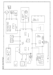
... 48 P17 MIO MIO RELAY 24V 24VB P8 (CONNECTOR) 16 P6 BOARD PCB P11 P4 P15 C B48K159 4 8 8 C P4 16 HIGH VOLTAGE POWER FUSER UNIT 8 P3 LOW SUPPLY ASSY THERMISTOR FUSER PCB EJECT SENSOR B48K142 LAMP DRIVER VOLTAGE POWER SUPPLY ASSY 8 OPTION UNIT B48K186 2 P1 P2 4 2 P1 HEATER THERMO STAT INLET POWER SW...
... 48 P17 MIO MIO RELAY 24V 24VB P8 (CONNECTOR) 16 P6 BOARD PCB P11 P4 P15 C B48K159 4 8 8 C P4 16 HIGH VOLTAGE POWER FUSER UNIT 8 P3 LOW SUPPLY ASSY THERMISTOR FUSER PCB EJECT SENSOR B48K142 LAMP DRIVER VOLTAGE POWER SUPPLY ASSY 8 OPTION UNIT B48K186 2 P1 P2 4 2 P1 HEATER THERMO STAT INLET POWER SW...

Service Manual
Page 143
... Motor Fixing Unit Figure 3.5 Engine Controller Block Diagram Components in the Circuit (refer to the next page) A. Engine Control CPU B. Safety Door Switch Circuit III - 6 Fuser Unit Control C-1. Paper Feeder PCB Control Signals and Connector E. Fan Motor Drive Circuit H-1. Heater Temperature Input Signal C-3. Main Motor Control Circuit J.
... Motor Fixing Unit Figure 3.5 Engine Controller Block Diagram Components in the Circuit (refer to the next page) A. Engine Control CPU B. Safety Door Switch Circuit III - 6 Fuser Unit Control C-1. Paper Feeder PCB Control Signals and Connector E. Fan Motor Drive Circuit H-1. Heater Temperature Input Signal C-3. Main Motor Control Circuit J.

Service Manual
Page 148
DC motor harness 4P Polygon harness 5P SCN fan harness 2P HV harness 16P LV harness 8P Fan harness 3P Fuser harness 4P SCN flat cable 6P Feed flat cable 20P Switch flat cable 21P Figure 4.6 (6) Remove the main PCB assy. 7 screws Main PCB assy Figure 4.7 IV - 4 (4) Remove the switch flat cable 21P and the feed flat cable 20P. (5) Remove the fan harness 3P, the fuser harness 4P, the Polygon harness 5P, the SCN flat cable 6P, the DC motor harness 4P, the SCN fan harness 2P, the HV harness 16P and the LV harness 8P.
DC motor harness 4P Polygon harness 5P SCN fan harness 2P HV harness 16P LV harness 8P Fan harness 3P Fuser harness 4P SCN flat cable 6P Feed flat cable 20P Switch flat cable 21P Figure 4.6 (6) Remove the main PCB assy. 7 screws Main PCB assy Figure 4.7 IV - 4 (4) Remove the switch flat cable 21P and the feed flat cable 20P. (5) Remove the fan harness 3P, the fuser harness 4P, the Polygon harness 5P, the SCN flat cable 6P, the DC motor harness 4P, the SCN fan harness 2P, the HV harness 16P and the LV harness 8P.

Service Manual
Page 156
...-voltage supply PCB connector higher than that of P11-1 in the main PCB No Replace the fuser harness Feed flat cable connector rise from 0V to 5V when the eject or the feed flat cable. Fuser harness 3 Does the voltage of P4-11, power supply PCB assy. M-9 "16 TONER EMPTY " is displayed...
...-voltage supply PCB connector higher than that of P11-1 in the main PCB No Replace the fuser harness Feed flat cable connector rise from 0V to 5V when the eject or the feed flat cable. Fuser harness 3 Does the voltage of P4-11, power supply PCB assy. M-9 "16 TONER EMPTY " is displayed...

Service Manual
Page 159
... BD MALF" is displayed Possible cause Step Check Result Remedy Thermal fuse 1 Is the thermal fuse located in the fixing unit conductive? VI - 7 M-14 "50 FUSER MALF" is displayed Possible cause Step Check Result Remedy Main PCB 1 Scanner harness Is the problem remedied when the power off and on again? Even...
... BD MALF" is displayed Possible cause Step Check Result Remedy Thermal fuse 1 Is the thermal fuse located in the fixing unit conductive? VI - 7 M-14 "50 FUSER MALF" is displayed Possible cause Step Check Result Remedy Main PCB 1 Scanner harness Is the problem remedied when the power off and on again? Even...

Service Manual
Page 164
... a few seconds, then turn it on again. Wait a few seconds, then turn it on again. See M-13. Table 6.3 Service Call Messages Service Call Message 50 FUSER MALF 51 LASER BD MALF 52 SCANNER MALF 53 DX FAN MALF 54 MOTOR MALF 55 HIGH VOL MALF 61 PROG ERROR 62 FONT ERROR... 63 D-RAM ERROR 66 NV-W ERROR 67 NV-R ERROR 68 NV-B ERROR 60 SYSTEM ERROR XXXXX Meaning Malfunction of fuser Malfunction of laser beam detector Malfunction of laser scanner motor Malfunction of highvoltage power supply Program ROM checksum error Font ROM checksum error D-RAM error...
... a few seconds, then turn it on again. Wait a few seconds, then turn it on again. See M-13. Table 6.3 Service Call Messages Service Call Message 50 FUSER MALF 51 LASER BD MALF 52 SCANNER MALF 53 DX FAN MALF 54 MOTOR MALF 55 HIGH VOL MALF 61 PROG ERROR 62 FONT ERROR... 63 D-RAM ERROR 66 NV-W ERROR 67 NV-R ERROR 68 NV-B ERROR 60 SYSTEM ERROR XXXXX Meaning Malfunction of fuser Malfunction of laser beam detector Malfunction of laser scanner motor Malfunction of highvoltage power supply Program ROM checksum error Font ROM checksum error D-RAM error...
Service Manual
Page 167
... P13 21 3 4 20 P2 P5 P1 P12 P7 P3 MAIN PCB B48K234 (HL-1260e) B48K259 (HL-1660) RISC CPU I/L SW ENGINE CPU P10 P9 5 6 6 P1 5 LD DRIVE PCB B48K165 (HL-1260e) B48K253 (HL-1660) D SCANNER MOTOR DRIVER SCAN MOTOR P14 MIO INTERFACE VIDEO PART 5V 5VB ... RELAY 24V 24VB P8 (CONNECTOR) PCB P11 P4 P15 BOARD B48K235 4 8 8 P19 16 P6 2 DC E HL-1660 only FAN P4 16 HIGH VOLTAGE POWER F F SUPPLY FUSER UNIT 8 P3 LOW ASSY FUSER PCB VOLTAGE B48K186 EJECT SENSOR POWER LAMP SUPPLY 8 THERMISTOR B48K142 DRIVER ASSY OPTION UNIT G G 2 P1 P2 4...
... P13 21 3 4 20 P2 P5 P1 P12 P7 P3 MAIN PCB B48K234 (HL-1260e) B48K259 (HL-1660) RISC CPU I/L SW ENGINE CPU P10 P9 5 6 6 P1 5 LD DRIVE PCB B48K165 (HL-1260e) B48K253 (HL-1660) D SCANNER MOTOR DRIVER SCAN MOTOR P14 MIO INTERFACE VIDEO PART 5V 5VB ... RELAY 24V 24VB P8 (CONNECTOR) PCB P11 P4 P15 BOARD B48K235 4 8 8 P19 16 P6 2 DC E HL-1660 only FAN P4 16 HIGH VOLTAGE POWER F F SUPPLY FUSER UNIT 8 P3 LOW ASSY FUSER PCB VOLTAGE B48K186 EJECT SENSOR POWER LAMP SUPPLY 8 THERMISTOR B48K142 DRIVER ASSY OPTION UNIT G G 2 P1 P2 4...

Service Manual
Page 192
... 1 UK2701001 1 P FEED/SIZE-SW PCB ASSY (SP) 2 UH2410000 1 SIZE SWITCH SPRING 3 087320616 1 TAPTITE, CUP S M3X6 SYMBOL B48K139/140200B/200B REMARK MODEL HL-1260e 54T-U01-090 1. PR98046 MODEL HL-1260e 54T-U01-050/070 2. PAPER FEEDER PCB REF.NO. CODE Q'TY DESCRIPTION 1A UH1052001 1 AC CORD, VDE 1B UH1053001 1 AC CORD... U34322001 1 AC CORD #6, ISRAEL 1I U34342001 1 AC CORD #8, BS/SINGAPORE 2 UK2502001 1 HV HARNESS 16P 3 UK2505001 1 FEED FLAT CABLE 20P 4 UK2506001 1 LV HARNESS 8P 5 UK2507001 1 FUSER HARNESS 4P 6 UK2508001 1 DC MOTOR HARNESS 4P REMARK T/I NO.
... 1 UK2701001 1 P FEED/SIZE-SW PCB ASSY (SP) 2 UH2410000 1 SIZE SWITCH SPRING 3 087320616 1 TAPTITE, CUP S M3X6 SYMBOL B48K139/140200B/200B REMARK MODEL HL-1260e 54T-U01-090 1. PR98046 MODEL HL-1260e 54T-U01-050/070 2. PAPER FEEDER PCB REF.NO. CODE Q'TY DESCRIPTION 1A UH1052001 1 AC CORD, VDE 1B UH1053001 1 AC CORD... U34322001 1 AC CORD #6, ISRAEL 1I U34342001 1 AC CORD #8, BS/SINGAPORE 2 UK2502001 1 HV HARNESS 16P 3 UK2505001 1 FEED FLAT CABLE 20P 4 UK2506001 1 LV HARNESS 8P 5 UK2507001 1 FUSER HARNESS 4P 6 UK2508001 1 DC MOTOR HARNESS 4P REMARK T/I NO.

Service Manual
Page 195
MAIN PCB, OTHERS TI No.96-P013 /96-P046 MODEL HL-1260e 54T-U01-100 SOLDERING SOLDER POINT SP1 SP2 SP3 SP4 SP5 SP6 CP5 OPEN TRANSACT CUT SHORT CUT POINT TRANSACT CP1 9.8304MHZ OPTION P15 ... D5 R72 R73 Q22 L5 C188 (WHITE) 4 1 1 C190 ZD2 ZD1 C88 RA42 C92 33 RA47 R71 32 Q21 R70 R69 C84 C82 R68 C80 P11 FUSER HC14 #40 79R3041 RA39 #25 RA36 R67 C79 RA35 RA37 C40 C33 LS244 ROM1L 12 CH3 11 RST #22 1 84 75 74 C73 RA32 RA33...
MAIN PCB, OTHERS TI No.96-P013 /96-P046 MODEL HL-1260e 54T-U01-100 SOLDERING SOLDER POINT SP1 SP2 SP3 SP4 SP5 SP6 CP5 OPEN TRANSACT CUT SHORT CUT POINT TRANSACT CP1 9.8304MHZ OPTION P15 ... D5 R72 R73 Q22 L5 C188 (WHITE) 4 1 1 C190 ZD2 ZD1 C88 RA42 C92 33 RA47 R71 32 Q21 R70 R69 C84 C82 R68 C80 P11 FUSER HC14 #40 79R3041 RA39 #25 RA36 R67 C79 RA35 RA37 C40 C33 LS244 ROM1L 12 CH3 11 RST #22 1 84 75 74 C73 RA32 RA33...

Service Manual
Page 197
... C174 SW1 + C2 RA1 R1 1 2 35 P2 SP6 36 IC CARD C1 63736384 +24V 2 P1 1 PANEL 20 21 6 . TI No.96-P013 / 96-P046 MODEL HL-1260e 54T-U01-104 SOLDERING SOLDER POINT SP1 SP2 SP3 SP4 SP5 SP6 CP5 OPEN TRANSACT CUT SHORT CUT POINT TRANSACT CP1 9.8304MHZ OPTION P15... D5 R72 R73 Q22 L5 C188 (WHITE) 4 1 1 C190 ZD2 ZD1 C88 RA42 C92 33 RA47 R71 32 Q21 R70 R69 C84 C82 R68 C80 P11 FUSER R67 C79 RA35 RA32 RA37 C40 C33 LS244 ROM1L RA34 C173 R65 C53 C68 R66 C75 C72 C191 12 CH3 11 RST 75 74 C73...
... C174 SW1 + C2 RA1 R1 1 2 35 P2 SP6 36 IC CARD C1 63736384 +24V 2 P1 1 PANEL 20 21 6 . TI No.96-P013 / 96-P046 MODEL HL-1260e 54T-U01-104 SOLDERING SOLDER POINT SP1 SP2 SP3 SP4 SP5 SP6 CP5 OPEN TRANSACT CUT SHORT CUT POINT TRANSACT CP1 9.8304MHZ OPTION P15... D5 R72 R73 Q22 L5 C188 (WHITE) 4 1 1 C190 ZD2 ZD1 C88 RA42 C92 33 RA47 R71 32 Q21 R70 R69 C84 C82 R68 C80 P11 FUSER R67 C79 RA35 RA32 RA37 C40 C33 LS244 ROM1L RA34 C173 R65 C53 C68 R66 C75 C72 C191 12 CH3 11 RST 75 74 C73...


