
Service Manual
Page 4
......I-3 2.2 Functions ...I-3 2.3 Electrical and Mechanical ...I-4 2.4 Paper Specification ...I-5 2.5 Print Delivery...I-6 2.6 Paper ...I-6 2.7 Effective Printing Area ...I /O...II-14 1.4 Driver PCB ...II-14 1.5 SW Panel PCB...II-14 1.6 Power Supply ...II-15 1.6.1 Low-voltage Power Supply II-15 1.6.2 High-voltage Power Supply,... SR PCB II-16 2. SAFETY INFORMATION ...I-9 3.1 Laser Safety (110 - 120V Model only I-9 3.2 FDA Regulations (110 - 120V Model only I-9 3.3 Caution for Laser Product (Warnhinweis für Laserdrucker I-10 CHAPTER II THEORY OF OPERATION II-1 1....
......I-3 2.2 Functions ...I-3 2.3 Electrical and Mechanical ...I-4 2.4 Paper Specification ...I-5 2.5 Print Delivery...I-6 2.6 Paper ...I-6 2.7 Effective Printing Area ...I /O...II-14 1.4 Driver PCB ...II-14 1.5 SW Panel PCB...II-14 1.6 Power Supply ...II-15 1.6.1 Low-voltage Power Supply II-15 1.6.2 High-voltage Power Supply,... SR PCB II-16 2. SAFETY INFORMATION ...I-9 3.1 Laser Safety (110 - 120V Model only I-9 3.2 FDA Regulations (110 - 120V Model only I-9 3.3 Caution for Laser Product (Warnhinweis für Laserdrucker I-10 CHAPTER II THEORY OF OPERATION II-1 1....

Service Manual
Page 5
... PCB / Relay PCB ...III-9 3.8 Fixing Unit ...III-10 3.9 Scanner Unit ...III-12 3.10 Main PCB ASSY ...III-14 3.11 Base Plate ASSY ...III-15 3.12 Driver PCB ASSY ...III-16 3.13 Low-voltage Power Supply PCB ASSY III-17 3.14 High-voltage Power Supply PCB ASSY III-18 3.15 Fan Motor...
... PCB / Relay PCB ...III-9 3.8 Fixing Unit ...III-10 3.9 Scanner Unit ...III-12 3.10 Main PCB ASSY ...III-14 3.11 Base Plate ASSY ...III-15 3.12 Driver PCB ASSY ...III-16 3.13 Low-voltage Power Supply PCB ASSY III-17 3.14 High-voltage Power Supply PCB ASSY III-18 3.15 Fan Motor...

Service Manual
Page 6
......IV-1 1.1 Initial Check ...IV-1 1.2 Basic Procedure...IV-2 2. INSPECTION MODE...IV-27 6.1 Incorporated Inspection Modes IV-27 6.2 Error Codes...IV-29 APPENDICES 1. Main PCB Circuit Diagram, (2/5 A-4 5. Driver PCB Circuit Diagram A-8 9. Switch Panel/Solenoid, Bin/Relay PCB Circuit Diagram A-9 10. Descriptions ...A-1 2. Main PCB Circuit Diagram, (5/5 A-7 8. High-voltage Power Supply PCB Circuit Diagram A-12...
......IV-1 1.1 Initial Check ...IV-1 1.2 Basic Procedure...IV-2 2. INSPECTION MODE...IV-27 6.1 Incorporated Inspection Modes IV-27 6.2 Error Codes...IV-29 APPENDICES 1. Main PCB Circuit Diagram, (2/5 A-4 5. Driver PCB Circuit Diagram A-8 9. Switch Panel/Solenoid, Bin/Relay PCB Circuit Diagram A-9 10. Descriptions ...A-1 2. Main PCB Circuit Diagram, (5/5 A-7 8. High-voltage Power Supply PCB Circuit Diagram A-12...
Service Manual
Page 7
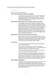
... compress graphic data and font data efficiently into your computer screen to print graphics in its printer hardware and the supplied printer driver software, which allows the printer to connect to 1200dpi Resolution and 10ppm Printing Speed True 600 dots per inch (dpi) with...x 600dpi mode.) Enhanced Printing Performance and User-Friendly Operation for Windows The dedicated printer driver and TrueTypeTM-compatible fonts for the corrective action to take. CHAPTER I -1 FEATURES This printer has the following features: UP to multiple peripheral devices. Use this function to let...
... compress graphic data and font data efficiently into your computer screen to print graphics in its printer hardware and the supplied printer driver software, which allows the printer to connect to 1200dpi Resolution and 10ppm Printing Speed True 600 dots per inch (dpi) with...x 600dpi mode.) Enhanced Printing Performance and User-Friendly Operation for Windows The dedicated printer driver and TrueTypeTM-compatible fonts for the corrective action to take. CHAPTER I -1 FEATURES This printer has the following features: UP to multiple peripheral devices. Use this function to let...

Service Manual
Page 8
When you can load A4, letter, legal, B5 and executive sizes of paper. The printer also supports Auto-emulation switching between HP and Epson or HP, BR-Script 2 and Epson or HP, Brother BR-Script 2 and IBM. The front Feeder 1 also allows manual paper loading, so you ... two economy modes 25% toner saving and 50% toner saving, through the Windows printer driver supplied with your printing cost by saving toner. Popular Printer Emulation Support This printer supports four printer emulation modes, HP LaserJet 6P, Brother BR-Script Level 2, Epson FX-850, and IBM Proprinter XL. If you can...
When you can load A4, letter, legal, B5 and executive sizes of paper. The printer also supports Auto-emulation switching between HP and Epson or HP, BR-Script 2 and Epson or HP, Brother BR-Script 2 and IBM. The front Feeder 1 also allows manual paper loading, so you ... two economy modes 25% toner saving and 50% toner saving, through the Windows printer driver supplied with your printing cost by saving toner. Popular Printer Emulation Support This printer supports four printer emulation modes, HP LaserJet 6P, Brother BR-Script Level 2, Epson FX-850, and IBM Proprinter XL. If you can...

Service Manual
Page 9
SPECIFICATIONS 2.1 Printing Print method Electrophotography by semiconductor laser beam scanning Resolution 1200 (H) x 600 (V) dpi (for Windows DIB graphics) 600 x 600dpi (for Windows / DOS) 300 x 300dpi (under Apple ... among HP LaserJet 5P, EPSON FX-850, and IBM Proprinter XL BR-Script Printer driver Windows 95 / WindowsTM 3.1/3.11 driver, supporting Brother Printing Solution for Windows, Brother Native Compression mode and bi-directional capability Optional Macintosh® driver available for System 6.0.7 or higher Interface Bi-directional parallel interface Universal Serial Bus ...
SPECIFICATIONS 2.1 Printing Print method Electrophotography by semiconductor laser beam scanning Resolution 1200 (H) x 600 (V) dpi (for Windows DIB graphics) 600 x 600dpi (for Windows / DOS) 300 x 300dpi (under Apple ... among HP LaserJet 5P, EPSON FX-850, and IBM Proprinter XL BR-Script Printer driver Windows 95 / WindowsTM 3.1/3.11 driver, supporting Brother Printing Solution for Windows, Brother Native Compression mode and bi-directional capability Optional Macintosh® driver available for System 6.0.7 or higher Interface Bi-directional parallel interface Universal Serial Bus ...
Service Manual
Page 18
1.2 Main PCB Block Diagram Fig. 2.2 shows the block diagram of the main PCB. A S I C Reset Circuit CPU Core MB86831PFV BUS INT Oscillator (33.333333MHz) Program + Font ROM (8Mbytes) Flash Memory (1Mbytes) RAM (4Mbytes) Address Decoder DRAM Control Timer FIFO DATA EXTENSION Option RAM (SIMM) (Max. 32Mbytes) Option Serial I/O (RS232C & RS422A) Parallel I/O USB I/O Software Support To PC To PC EEPROM (512 x 8bits) EEPROM I/O Motor Driver Engine Control I/O To Panel Sensor PCB Fig. 2.2 II-2
1.2 Main PCB Block Diagram Fig. 2.2 shows the block diagram of the main PCB. A S I C Reset Circuit CPU Core MB86831PFV BUS INT Oscillator (33.333333MHz) Program + Font ROM (8Mbytes) Flash Memory (1Mbytes) RAM (4Mbytes) Address Decoder DRAM Control Timer FIFO DATA EXTENSION Option RAM (SIMM) (Max. 32Mbytes) Option Serial I/O (RS232C & RS422A) Parallel I/O USB I/O Software Support To PC To PC EEPROM (512 x 8bits) EEPROM I/O Motor Driver Engine Control I/O To Panel Sensor PCB Fig. 2.2 II-2

Service Manual
Page 30
Fig. 2.16 1.4 Driver PCB The following parts are mounted on the SW panel PCB. • Operation panel ........1 Key, 5 LEDs II-14 1.3.12 Paper Feed Motor Drive Circuit A DC motor is used for main PCB • Registration sensor 1.5 SW Panel PCB The following parts are mounted on the driver PCB. • Connectors Low-voltage, high-voltage, solenoid, main motor, toner sensor, laser, polygon motor, connector for paper feeding. Fig. 2.15 1.3.13 USB I/O Fig. 2.17 shows the USB interface circuit.
Fig. 2.16 1.4 Driver PCB The following parts are mounted on the SW panel PCB. • Operation panel ........1 Key, 5 LEDs II-14 1.3.12 Paper Feed Motor Drive Circuit A DC motor is used for main PCB • Registration sensor 1.5 SW Panel PCB The following parts are mounted on the driver PCB. • Connectors Low-voltage, high-voltage, solenoid, main motor, toner sensor, laser, polygon motor, connector for paper feeding. Fig. 2.15 1.3.13 USB I/O Fig. 2.17 shows the USB interface circuit.

Service Manual
Page 31
1.6 Power Supply 1.6.1 Low-voltage Power Supply The power supply uses a switching regulation system to generate the regulated DC power (+5V and +24V), which are converted from the AC line. Fuse Lightning Surge Absorber Heater Circuit (Heater) Thermal Fuse Lamp Fuse Feedback Line Filter Rectifier Oscillator 24V Regulation Circuit 5V Regulation Circuit Fig. 2.17 II-15 (Driver Circuit) 24V 5V
1.6 Power Supply 1.6.1 Low-voltage Power Supply The power supply uses a switching regulation system to generate the regulated DC power (+5V and +24V), which are converted from the AC line. Fuse Lightning Surge Absorber Heater Circuit (Heater) Thermal Fuse Lamp Fuse Feedback Line Filter Rectifier Oscillator 24V Regulation Circuit 5V Regulation Circuit Fig. 2.17 II-15 (Driver Circuit) 24V 5V

Service Manual
Page 33
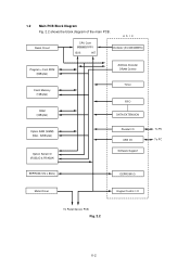
...Pressure Roller Paper Pick-up Roller Pinch Roller Hopper Plate Paper Feed Roller Registration Sensor Lever Toner Cartridge Polygon Mirror Toner Laser Scanner Empty Sensor Supply Roller Eject Roller Eject Sensor Actuator Heat Roller Develop- Thermistor ment Roller Cleaning Roller Corona Wire ...Scanner Unit Fig. 2.19 Main Cotrol PCB Driver PCB EL PCB SW Panel PCB Scanner Unit Main Motor Fan Motor HighVoltage Power Supply Solenoid Resist Primary Charger (Corona Wire)...
...Pressure Roller Paper Pick-up Roller Pinch Roller Hopper Plate Paper Feed Roller Registration Sensor Lever Toner Cartridge Polygon Mirror Toner Laser Scanner Empty Sensor Supply Roller Eject Roller Eject Sensor Actuator Heat Roller Develop- Thermistor ment Roller Cleaning Roller Corona Wire ...Scanner Unit Fig. 2.19 Main Cotrol PCB Driver PCB EL PCB SW Panel PCB Scanner Unit Main Motor Fan Motor HighVoltage Power Supply Solenoid Resist Primary Charger (Corona Wire)...

Service Manual
Page 42
DISASSEMBLY FLOW III-2 1 DRUM UNIT B 2 OUTPUT TRAY ASSY 3 TOP COVER A BOTTOM 10 MAIN PCB ASSY B 11 BASE PLATE ASSY 12 DRIVER PCB 4 5 MP SHEET FEEDER ASSY 6 UNDER SHOOT ASSY 8 FIXING UNIT 7 SR PCB / RELAY PCB C 9 SCANNER UNIT A 19 PAPER SUPPORT 20 EXTENSION SUPPORT WIRE 13 LOW-VOLTAGE PS PCB ASSY C 16 DRIVE UNIT 17 MAIN MOTOR ASSY 18 GEARS and SOLENOID 14 HIGH-VOLTAGE PS PCB ASSY 15 FAN MOTOR 2.
DISASSEMBLY FLOW III-2 1 DRUM UNIT B 2 OUTPUT TRAY ASSY 3 TOP COVER A BOTTOM 10 MAIN PCB ASSY B 11 BASE PLATE ASSY 12 DRIVER PCB 4 5 MP SHEET FEEDER ASSY 6 UNDER SHOOT ASSY 8 FIXING UNIT 7 SR PCB / RELAY PCB C 9 SCANNER UNIT A 19 PAPER SUPPORT 20 EXTENSION SUPPORT WIRE 13 LOW-VOLTAGE PS PCB ASSY C 16 DRIVE UNIT 17 MAIN MOTOR ASSY 18 GEARS and SOLENOID 14 HIGH-VOLTAGE PS PCB ASSY 15 FAN MOTOR 2.

Service Manual
Page 49
... Cover High-voltage cover SR harness ASSY SR PCB Fig. 3.13 (3) Disconnect the connector of the SR harness ASSY connecting the SR PCB and the driver PCB and remove the high-voltage cover. 3.7 SR PCB / Relay PCB (1) Remove the SR protect sheet. (2) Disconnect the connector of the relay harness ASSY connecting...
... Cover High-voltage cover SR harness ASSY SR PCB Fig. 3.13 (3) Disconnect the connector of the SR harness ASSY connecting the SR PCB and the driver PCB and remove the high-voltage cover. 3.7 SR PCB / Relay PCB (1) Remove the SR protect sheet. (2) Disconnect the connector of the relay harness ASSY connecting...

Service Manual
Page 53
Screw Toner Sensor PCB Tape Fig. 3.21 Scanner Unit III-13 Note: Never touch the inside of the scanner unit or the mirror when disassembling or reassembling. Screw Scanner Unit Screws Main Cover Fig. 3.20 Driver PCB (3) Disconnect the three connectors from the driver PCB. (4) Remove the screw and the tape, and lift the toner sensor PCB from the scanner unit. 3.9 Scanner Unit (1) Remove the three screws. (2) Lift out the scanner unit. If there is any dirt or dust on the mirror, blow it off.
Screw Toner Sensor PCB Tape Fig. 3.21 Scanner Unit III-13 Note: Never touch the inside of the scanner unit or the mirror when disassembling or reassembling. Screw Scanner Unit Screws Main Cover Fig. 3.20 Driver PCB (3) Disconnect the three connectors from the driver PCB. (4) Remove the screw and the tape, and lift the toner sensor PCB from the scanner unit. 3.9 Scanner Unit (1) Remove the three screws. (2) Lift out the scanner unit. If there is any dirt or dust on the mirror, blow it off.

Service Manual
Page 56
Note: See the Fig. 3.26 about the position installing the dumping material and the soundproof sponge A, B. Dumping material Soundproof sponge A Fig. 3.26 Soundproof sponge B Soundproof sponge A 3.12 Driver PCB ASSY (1) Remove the screw securing the driver PCB ASSY. (Slide the PCB A from underneath the main shield.) A Screw Driver PCB ASSY Main Shield Insulation tape Fig. 3.27 Driver PCB ASSY III-16
Note: See the Fig. 3.26 about the position installing the dumping material and the soundproof sponge A, B. Dumping material Soundproof sponge A Fig. 3.26 Soundproof sponge B Soundproof sponge A 3.12 Driver PCB ASSY (1) Remove the screw securing the driver PCB ASSY. (Slide the PCB A from underneath the main shield.) A Screw Driver PCB ASSY Main Shield Insulation tape Fig. 3.27 Driver PCB ASSY III-16

Service Manual
Page 57
...harness 11. Toner harness 4. Note 2: The connectors should be stressed by matching the housing color and the number of the harnesses) 1. Laser harness 5. Main motor harness 13. Solenoid harness 12. (2) Disconnect the eleven connectors from the PCB. (Three connectors have already been ...disconnected when removing the scanner unit.) 5 1 Driver PCB ASSY 2 7 4 3 8 9 10 11 12 13 Main frame Fig. 3.28 (Name of pins. 3.13 Low-voltage Power Supply PCB ...
...harness 11. Toner harness 4. Note 2: The connectors should be stressed by matching the housing color and the number of the harnesses) 1. Laser harness 5. Main motor harness 13. Solenoid harness 12. (2) Disconnect the eleven connectors from the PCB. (Three connectors have already been ...disconnected when removing the scanner unit.) 5 1 Driver PCB ASSY 2 7 4 3 8 9 10 11 12 13 Main frame Fig. 3.28 (Name of pins. 3.13 Low-voltage Power Supply PCB ...

Service Manual
Page 69
...No No No Yes Remedy Set it to the center detect position. Toner sensor failure. Replace the driver PCB or the main PCB. I-1 Light Possible cause Density dial Toner sensing failure (printer side) Toner sensing failure (toner cartridge side) Drum connection failure High-voltage power supply PCB failure... contacts and grounding contacts. Can printing be followed in the printer body and on the drum unit. The wiper of specific image defects. HV.GND contacts (Fig.4-5) ➀ IV-5 Check the harness connection between the driver PCB and the main PCB. Is the problem solved by ...
...No No No Yes Remedy Set it to the center detect position. Toner sensor failure. Replace the driver PCB or the main PCB. I-1 Light Possible cause Density dial Toner sensing failure (printer side) Toner sensing failure (toner cartridge side) Drum connection failure High-voltage power supply PCB failure... contacts and grounding contacts. Can printing be followed in the printer body and on the drum unit. The wiper of specific image defects. HV.GND contacts (Fig.4-5) ➀ IV-5 Check the harness connection between the driver PCB and the main PCB. Is the problem solved by ...

Service Manual
Page 70
...disconnected connectors? No Clean both electrodes. 4 Is the problem solved when the Yes Replace the drum drum unit is replaced? No Replace the driver PCB. power supply. 6 Are there any disconnected connectors? I-2 Dark Possible cause Density dial Corona failure (soiled wire) Corona failure (contact ... dirty? Yes Clean the corona wire by using the wire cleaner. 3 Are the corona electrodes between the printer body and drum unit dirty? power supply PCB Main PCB Driver PCB Step Check Result Remedy 1 Is the density dial at the center click position? HV.GND contacts ...
...disconnected connectors? No Clean both electrodes. 4 Is the problem solved when the Yes Replace the drum drum unit is replaced? No Replace the driver PCB. power supply. 6 Are there any disconnected connectors? I-2 Dark Possible cause Density dial Corona failure (soiled wire) Corona failure (contact ... dirty? Yes Clean the corona wire by using the wire cleaner. 3 Are the corona electrodes between the printer body and drum unit dirty? power supply PCB Main PCB Driver PCB Step Check Result Remedy 1 Is the density dial at the center click position? HV.GND contacts ...

Service Manual
Page 71
...unit is broken or loose. No Check the connection between the printer body and drum unit dirty? 2 Are the drum shaft and drum electrode of the printer body connected correctly? 3 Is the problem solved after the main PCB or the driver PCB replaced? 6 Scanner interlock lever damaged. Yes Replace the ...main PCB or the driver PCB. Yes Clean the shaft and the electrode. Yes Replace the...
...unit is broken or loose. No Check the connection between the printer body and drum unit dirty? 2 Are the drum shaft and drum electrode of the printer body connected correctly? 3 Is the problem solved after the main PCB or the driver PCB replaced? 6 Scanner interlock lever damaged. Yes Replace the ...main PCB or the driver PCB. Yes Clean the shaft and the electrode. Yes Replace the...

Service Manual
Page 72
... Harness connection H.V. Yes Replace the main PCB. Yes Check the harness connection between the scanner unit and the driver PCB. Yes Replace the driver PCB. Yes Clean the terminals in the printer and on the bottom face of the drum unit broken? 2 Are the electric terminal springs in step 3. ...6 Is the problem solved after main PCB replaced? 7 Is the problem solved after H.V. power supply PCB. power supply PCB Ditto Main PCB Driver PCB Step Check 1 ...
... Harness connection H.V. Yes Replace the main PCB. Yes Check the harness connection between the scanner unit and the driver PCB. Yes Replace the driver PCB. Yes Clean the terminals in the printer and on the bottom face of the drum unit broken? 2 Are the electric terminal springs in step 3. ...6 Is the problem solved after main PCB replaced? 7 Is the problem solved after H.V. power supply PCB. power supply PCB Ditto Main PCB Driver PCB Step Check 1 ...

Service Manual
Page 86
... malfunctions with the power plug inserted into the outlet? Is there a broken wire between the terminals. Turn the power switch ON again. lead pin Voltage Driver P13-4.5 P13-2.3 Approx. 24V P13-8.9 P13-6.7 Approx. 5V Result No Yes No Remedy Follow the same check procedure of the low-voltage power supply and... outlet? 3 is activated, check the connector, the wiring from the connector, and the DC load. Turn the power switch OFF and disconnect the P13 connector (Driver PCB). PCB + lead pin - Replace the low-voltage power supply PCB.
... malfunctions with the power plug inserted into the outlet? Is there a broken wire between the terminals. Turn the power switch ON again. lead pin Voltage Driver P13-4.5 P13-2.3 Approx. 24V P13-8.9 P13-6.7 Approx. 5V Result No Yes No Remedy Follow the same check procedure of the low-voltage power supply and... outlet? 3 is activated, check the connector, the wiring from the connector, and the DC load. Turn the power switch OFF and disconnect the P13 connector (Driver PCB). PCB + lead pin - Replace the low-voltage power supply PCB.


