The Bose® Lifestyle® amplifier - Owner's guide
Page 6
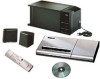
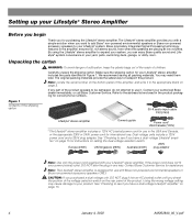
... to be damaged, do not attempt to your authorized Bose dealer immediately, or call Bose Customer Service. Unpacking the carton WARNING: To avoid danger of suffocation, keep the plastic bags out of the reach of the shipping carton 30-ft audio input cable PN197406 Lifestyle® stereo amplifier Owner's guide Power cord...
... to be damaged, do not attempt to your authorized Bose dealer immediately, or call Bose Customer Service. Unpacking the carton WARNING: To avoid danger of suffocation, keep the plastic bags out of the reach of the shipping carton 30-ft audio input cable PN197406 Lifestyle® stereo amplifier Owner's guide Power cord...
The Bose® Lifestyle® amplifier - Owner's guide
Page 7
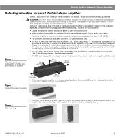
...DO NOT PLACE THE AMPLIFIER IN A COMPLETELY ENCLOSED AREA - Like all sides of the amplifier with an open area of the supplied 30-foot audio input cable. • Place the amplifier in an area where the maximum ambient temperature is installed on a shelf, or ... its volume level in . (5.0 cm) • When mounting the amplifier on boats. If adequate ventilation is important to either your Lifestyle® system or the accessory speakers, consider the following guidelines. Figure 2 Required clearance between the amplifier and any heat-sensitive surface, ...
...DO NOT PLACE THE AMPLIFIER IN A COMPLETELY ENCLOSED AREA - Like all sides of the amplifier with an open area of the supplied 30-foot audio input cable. • Place the amplifier in an area where the maximum ambient temperature is installed on a shelf, or ... its volume level in . (5.0 cm) • When mounting the amplifier on boats. If adequate ventilation is important to either your Lifestyle® system or the accessory speakers, consider the following guidelines. Figure 2 Required clearance between the amplifier and any heat-sensitive surface, ...
The Bose® Lifestyle® amplifier - Owner's guide
Page 9
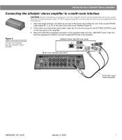
... cable into the L (left) INPUT jack. SPSEPAEKAEKREROOUUTPTUPUTSTS INPUT 30-ft audio input cable (supplied) AM262840_00_V.pdf January 4, 2002 7 At the other connections. 1. Setting Up Your Lifestyle® Stereo Amplifier Connecting the Lifestyle® stereo amplifier to a multi-room interface ... connector at one end of the amplifier. 3. Figure 6 Cable connections between a multi-room interface and the Lifestyle® stereo amplifier Lifestyle® stereo amplifier rear panel Multi-room interface rear panel 4 Ω MINIMUM LL R L SYSTEM RR ...
... cable into the L (left) INPUT jack. SPSEPAEKAEKREROOUUTPTUPUTSTS INPUT 30-ft audio input cable (supplied) AM262840_00_V.pdf January 4, 2002 7 At the other connections. 1. Setting Up Your Lifestyle® Stereo Amplifier Connecting the Lifestyle® stereo amplifier to a multi-room interface ... connector at one end of the amplifier. 3. Figure 6 Cable connections between a multi-room interface and the Lifestyle® stereo amplifier Lifestyle® stereo amplifier rear panel Multi-room interface rear panel 4 Ω MINIMUM LL R L SYSTEM RR ...
The Bose® Lifestyle® amplifier - Owner's guide
Page 11
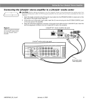
... (Figure 8). 2. Insert the red RCA piggyback connector into the L (left) INPUT jack. Figure 8 Cable connections between the Lifestyle® media center and the Lifestyle® stereo amplifier Lifestyle® SA-1 stereo amplifier rear panel Lifestyle® media center rear panel 30-ft audio input cable (supplied) AM262840_00_V.pdf January 4, 2002 9 Setting Up Your...
... (Figure 8). 2. Insert the red RCA piggyback connector into the L (left) INPUT jack. Figure 8 Cable connections between the Lifestyle® media center and the Lifestyle® stereo amplifier Lifestyle® SA-1 stereo amplifier rear panel Lifestyle® media center rear panel 30-ft audio input cable (supplied) AM262840_00_V.pdf January 4, 2002 9 Setting Up Your...
The Bose® Lifestyle® amplifier - Owner's guide
Page 13
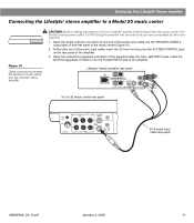
At the other connections. 1. Lifestyle® stereo amplifier rear panel 4 Ω MINIMUM LL R L SYSTEM RR CONTROL L R +- SPEAKER OUTPUTS INPUT Model 20 music center rear panel 30-ft audio input cable (supplied) AM262840_00_V.pdf January 4, 2002 11 Insert the single multi-pin connector at one...-plug into the SPEAKER ZONES 2 output jack on the rear panel of the amplifier. 3. Setting Up Your Lifestyle® Stereo Amplifier Connecting the Lifestyle® stereo amplifier to a Model 20 music center ® Figure 10 Cable connections between the Model 20 ...
At the other connections. 1. Lifestyle® stereo amplifier rear panel 4 Ω MINIMUM LL R L SYSTEM RR CONTROL L R +- SPEAKER OUTPUTS INPUT Model 20 music center rear panel 30-ft audio input cable (supplied) AM262840_00_V.pdf January 4, 2002 11 Insert the single multi-pin connector at one...-plug into the SPEAKER ZONES 2 output jack on the rear panel of the amplifier. 3. Setting Up Your Lifestyle® Stereo Amplifier Connecting the Lifestyle® stereo amplifier to a Model 20 music center ® Figure 10 Cable connections between the Model 20 ...
The Bose® Lifestyle® amplifier - Owner's guide
Page 15
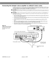
...CONTROL 2 ~ POWER 12VAC IN 1.0A ANTENNA SEE INSTRUCTION MANUAL Fixed speaker outputs 30-ft audio input cable (supplied) Acoustimass module cable AM262840_00_V.pdf January 4, 2002 13 Setting Up Your Lifestyle® Stereo Amplifier Connecting the Lifestyle® stereo amplifier to a Model 5 music center In systems using... jack and the white RCA connector into the white piggyback jack. CAUTION: DO NOT connect the audio input cable for the Lifestyle® stereo amplifier to temporarily unplug the theater speakers from the AC (mains) power outlet. At the other ...
...CONTROL 2 ~ POWER 12VAC IN 1.0A ANTENNA SEE INSTRUCTION MANUAL Fixed speaker outputs 30-ft audio input cable (supplied) Acoustimass module cable AM262840_00_V.pdf January 4, 2002 13 Setting Up Your Lifestyle® Stereo Amplifier Connecting the Lifestyle® stereo amplifier to a Model 5 music center In systems using... jack and the white RCA connector into the white piggyback jack. CAUTION: DO NOT connect the audio input cable for the Lifestyle® stereo amplifier to temporarily unplug the theater speakers from the AC (mains) power outlet. At the other ...
The Bose® Lifestyle® amplifier - Owner's guide
Page 20
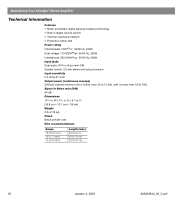
... Wire recommendations Gauge 18 (0.75 mm2) 16 (1.7 mm2) 14 (2.0 mm2) Length (max.) 30 ft (9 m) 45 ft (14 m) 70 ft (21 m) 18 January 4, 2002 AM262840_00_V.pdf W x 51/2 in . Maintaining Your Lifestyle® Stereo Amplifier Technical information Features • Bose® proprietary digital signal processing technology • Built-in . D x 31/8 in digital ...-DIN System control: 3.5 mm stereo mini-plug connector Input sensitivity 0.5 Vrms @ 1 kHz Output power (continuous average) 35W per channel minimum into 4 Ohms, from 30 to Noise ratio (S/N) 90 dB Dimensions 141/4 in .
... Wire recommendations Gauge 18 (0.75 mm2) 16 (1.7 mm2) 14 (2.0 mm2) Length (max.) 30 ft (9 m) 45 ft (14 m) 70 ft (21 m) 18 January 4, 2002 AM262840_00_V.pdf W x 51/2 in . Maintaining Your Lifestyle® Stereo Amplifier Technical information Features • Bose® proprietary digital signal processing technology • Built-in . D x 31/8 in digital ...-DIN System control: 3.5 mm stereo mini-plug connector Input sensitivity 0.5 Vrms @ 1 kHz Output power (continuous average) 35W per channel minimum into 4 Ohms, from 30 to Noise ratio (S/N) 90 dB Dimensions 141/4 in .

Owner's guide
Page 3
...Safety Information 2 Getting Started 6 Speaker connections 7 Connecting additionalBose powered speakers ...........13 Connections for Lifestyle powered speakers 13 Connections for the Bose Wave radio 15 Connecting the Lifestyle' music centers antennas and power 16 Special radio settings for your unit with a TV.... voltage models 18 Connecting other Lifestyle music systems 27 Listening in two different rooms 28 Using the optional deluxe Lifestyle' RC-10 remote control 28 Using the deluxe remote control between listening areas 30 Programming the CD player 31 ...
...Safety Information 2 Getting Started 6 Speaker connections 7 Connecting additionalBose powered speakers ...........13 Connections for Lifestyle powered speakers 13 Connections for the Bose Wave radio 15 Connecting the Lifestyle' music centers antennas and power 16 Special radio settings for your unit with a TV.... voltage models 18 Connecting other Lifestyle music systems 27 Listening in two different rooms 28 Using the optional deluxe Lifestyle' RC-10 remote control 28 Using the deluxe remote control between listening areas 30 Programming the CD player 31 ...

Owner's guide
Page 33
...a1, use theinfrared extension cable. Many components work with the unit) inanopen cabinet or a bookcase, or you may also want to the Lifestyles music center. Making the cables longer YourCE-1ControlExpander unit's 6-foot(2m)cable connects to control(seeFigure 27). You can aim this cable up to... 30 feet (10m) by connecting it to reach your unit farther from view in detail tater. Choosing a convenient location Place your CD changer ...
...a1, use theinfrared extension cable. Many components work with the unit) inanopen cabinet or a bookcase, or you may also want to the Lifestyles music center. Making the cables longer YourCE-1ControlExpander unit's 6-foot(2m)cable connects to control(seeFigure 27). You can aim this cable up to... 30 feet (10m) by connecting it to reach your unit farther from view in detail tater. Choosing a convenient location Place your CD changer ...
Owner's guide
Page 34
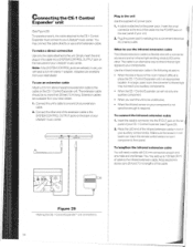
... the SYSTEM CONTROL OUTPUT jacks on the back of your extension cable. • When the infrared sensor on at one should benomore than 30 feet(10 m)long. you want the unit to be unobtrusive. 1. Connect the other . Make sure the broad infrared beam can aimat...situations: from your auxiliary component(s). Simply insert the end The infrared extension cable is an alternative way to direct infrared light signals to your lifestyle' music center. cableon the CE-1ControlExpander unit. z Figure 29 Making the CE-1Control Expander" unit connections. 34 Plug thepower pack's wall...
... the SYSTEM CONTROL OUTPUT jacks on the back of your extension cable. • When the infrared sensor on at one should benomore than 30 feet(10 m)long. you want the unit to be unobtrusive. 1. Connect the other . Make sure the broad infrared beam can aimat...situations: from your auxiliary component(s). Simply insert the end The infrared extension cable is an alternative way to direct infrared light signals to your lifestyle' music center. cableon the CE-1ControlExpander unit. z Figure 29 Making the CE-1Control Expander" unit connections. 34 Plug thepower pack's wall...

Owner's guide
Page 38
Maintaining Your Lifestyle" Music System Cleaning your remote control • en it clicks into ... batteries' + symbols with a soft-bristled attachment to clean the outside of them propedi' 3. lets eAr-sO r ' Figure 30 Changing the remote control's batteries. 38 Do not allow liquids to expose the battery compartment. 2. Note: Use threeAA orIECR6Pbatteries, orthe.../findingreplacementbatteries, contactBose Corporation directly(see "Customer Service,"page 39). 1. See Figure 30. Slide the battery cover back on the music center or bass module. You may also use any openings on .
Maintaining Your Lifestyle" Music System Cleaning your remote control • en it clicks into ... batteries' + symbols with a soft-bristled attachment to clean the outside of them propedi' 3. lets eAr-sO r ' Figure 30 Changing the remote control's batteries. 38 Do not allow liquids to expose the battery compartment. 2. Note: Use threeAA orIECR6Pbatteries, orthe.../findingreplacementbatteries, contactBose Corporation directly(see "Customer Service,"page 39). 1. See Figure 30. Slide the battery cover back on the music center or bass module. You may also use any openings on .

Owner's guide
Page 42
...10 deluxe remote control30 Operating considerations 30 Voltage selection Choosing a power pack 17 Lifestyle 3 speakers 11 Lifestyle powered speakers 14 Volume adjustment 23 Lifestyle 3 speakers 12 Lifestyle' powered speakers 14 Two-room listening 30 Warranty 40 ZONE switch 30 42 Index Antenna Connections 16 ...player listening to 25 Operating 25 Programming 31 Randomplay21, 30 CE-1ControlExpander unit 32 Entering component codes 35 Operation with a Lifestyle'remote control36 Channel spacing, AM andFM 18 Connections Additional Bose powered Speakers 13 AMantenna 17 Bass module power (mains)...
...10 deluxe remote control30 Operating considerations 30 Voltage selection Choosing a power pack 17 Lifestyle 3 speakers 11 Lifestyle powered speakers 14 Volume adjustment 23 Lifestyle 3 speakers 12 Lifestyle' powered speakers 14 Two-room listening 30 Warranty 40 ZONE switch 30 42 Index Antenna Connections 16 ...player listening to 25 Operating 25 Programming 31 Randomplay21, 30 CE-1ControlExpander unit 32 Entering component codes 35 Operation with a Lifestyle'remote control36 Channel spacing, AM andFM 18 Connections Additional Bose powered Speakers 13 AMantenna 17 Bass module power (mains)...


