The Bose® Lifestyle® amplifier - Owner's guide
Page 4
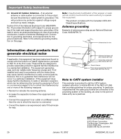
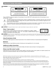
... AM262840_00_V.pdf Ground clamp Electric service equipment Antenna discharge unit (NEC Section 810-20) Grounding conductors (NEC Section 810-21) Ground clamps Power service grounding electrode system (NEC ART 250, Part H) Note to Article 820-40 of the NEC (of the FCC rules. Note: Unauthorized modification of the receiver or radio remote control could void the user's authority to operate this...
... AM262840_00_V.pdf Ground clamp Electric service equipment Antenna discharge unit (NEC Section 810-20) Grounding conductors (NEC Section 810-21) Ground clamps Power service grounding electrode system (NEC ART 250, Part H) Note to Article 820-40 of the NEC (of the FCC rules. Note: Unauthorized modification of the receiver or radio remote control could void the user's authority to operate this...

The Bose® Lifestyle® amplifier - Owner's guide
Page 12
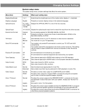
... code settings (switches 1, 2, 3, and 4) match those in more information on -screen display. 2. While your Lifestyle® DVD system is reset to Legacy. 5. On Off Mute All Mute SOURCE / INPUT CD/DVD Changer FM/AM TV VCR AUX MENU / NAVIGATION Settings Tune Disc Seek Enter Channel Chapter Preset Track Volume 1 2 3 4 5 6 7 8 9 0 PLAYBACK Stop Pause Play Shuffle Repeat Settings Settings ( ) System Setup Enter System Setup (3 of 3). Make sure switches 5, 7, and 8 are up a second remote control to "more...". ON Figure 9a Setting Zone 2 Protocol Setting Zone...
... code settings (switches 1, 2, 3, and 4) match those in more information on -screen display. 2. While your Lifestyle® DVD system is reset to Legacy. 5. On Off Mute All Mute SOURCE / INPUT CD/DVD Changer FM/AM TV VCR AUX MENU / NAVIGATION Settings Tune Disc Seek Enter Channel Chapter Preset Track Volume 1 2 3 4 5 6 7 8 9 0 PLAYBACK Stop Pause Play Shuffle Repeat Settings Settings ( ) System Setup Enter System Setup (3 of 3). Make sure switches 5, 7, and 8 are up a second remote control to "more...". ON Figure 9a Setting Zone 2 Protocol Setting Zone...
The Bose® Lifestyle® amplifier - Owner's guide
Page 15
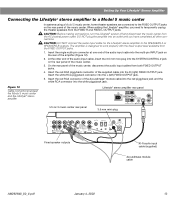
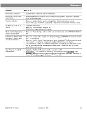
... mini-plug L R A B SPEAKERS OUTPUT FIXED REC PLAY AUX TAPE INPUT L R VIDEO SOUND AM LOOP 1 SYSTEM CONTROL 2 ~ POWER 12VAC IN 1.0A ANTENNA SEE INSTRUCTION MANUAL Fixed speaker outputs 30-ft audio input cable (supplied) Acoustimass module cable AM262840_00_V.pdf January 4, 2002 13 Insert the red RCA connector of the music center. 3. CAUTION: Before making connections, turn the Lifestyle® system off and disconnect the music center from both FIXED OUTPUT jacks. 4. Insert the white RCA piggyback connector into the SYSTEM CONTROL 2 jack on the rear panel...
... mini-plug L R A B SPEAKERS OUTPUT FIXED REC PLAY AUX TAPE INPUT L R VIDEO SOUND AM LOOP 1 SYSTEM CONTROL 2 ~ POWER 12VAC IN 1.0A ANTENNA SEE INSTRUCTION MANUAL Fixed speaker outputs 30-ft audio input cable (supplied) Acoustimass module cable AM262840_00_V.pdf January 4, 2002 13 Insert the red RCA connector of the music center. 3. CAUTION: Before making connections, turn the Lifestyle® system off and disconnect the music center from both FIXED OUTPUT jacks. 4. Insert the white RCA piggyback connector into the SYSTEM CONTROL 2 jack on the rear panel...

The Bose® Lifestyle® amplifier - Owner's guide
Page 18
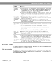
... not play. • Make sure the wires are in working order. • Be sure a music source is selected (AM, FM, CD, AUX, etc.). Refer to your Bose dealer to the piggyback jacks on the audio input cable.) • Disconnect any headphones. • Make sure the remote control switch settings are firmly connected at hardware stores. To clean the amplifier, use caulking, apply it only after installing the Lifestyle® stereo...
... not play. • Make sure the wires are in working order. • Be sure a music source is selected (AM, FM, CD, AUX, etc.). Refer to your Bose dealer to the piggyback jacks on the audio input cable.) • Disconnect any headphones. • Make sure the remote control switch settings are firmly connected at hardware stores. To clean the amplifier, use caulking, apply it only after installing the Lifestyle® stereo...
The Bose® Lifestyle® amplifier - Owner's guide
Page 19
If the speaker does not play, the problem is • Check the speaker wire connections. Bass or treble is in the system settings menu is overdriving the speakers. to -. • See "Connecting speakers to your Lifestyle® DVD system's owners guide. Interference • Make sure the speaker wires are firmly inserted in solving problems, contact Bose® Customer Service. This engages automatically if the volume is set too high and is set to "Legacy". Zone 2 does not •...
If the speaker does not play, the problem is • Check the speaker wire connections. Bass or treble is in the system settings menu is overdriving the speakers. to -. • See "Connecting speakers to your Lifestyle® DVD system's owners guide. Interference • Make sure the speaker wires are firmly inserted in solving problems, contact Bose® Customer Service. This engages automatically if the volume is set too high and is set to "Legacy". Zone 2 does not •...
Owner's guide
Page 2
... help you set up and operate your owner's guide for home and other licensing restrictions and protections. All rights reserved. NO USER-SERVICABLE PARTS INSIDE. IL NE SE TROUVE À L'INTÉRIEUR AUCUNE PIÈCE POUVANT ÊTRE RÉPARÉE PAR L'USAGER. CLASS 1 KLASSE 1 LUOKAN 1 KLASS 1 LASER PRODUCT LASER PRODUKT LASER LAITE LASER APPARAT CAUTION: Use of controls or adjustments...
... help you set up and operate your owner's guide for home and other licensing restrictions and protections. All rights reserved. NO USER-SERVICABLE PARTS INSIDE. IL NE SE TROUVE À L'INTÉRIEUR AUCUNE PIÈCE POUVANT ÊTRE RÉPARÉE PAR L'USAGER. CLASS 1 KLASSE 1 LUOKAN 1 KLASS 1 LASER PRODUCT LASER PRODUKT LASER LAITE LASER APPARAT CAUTION: Use of controls or adjustments...

Owner's guide
Page 9
...DVD player and turns the system on and off . Controls and Indicators The remote control The advanced radio-frequency remote control works from anywhere within most homes. Power Power - Note: Some types of this button turns your AUX device on and off and mute controls On Off Mute All Mute CD/DVD SOURCE / INPUT FM/AM Tape TV Input TV VCR AUX Power Power Power MENU / NAVIGATION DVD Menu Guide Exit Settings Tune Seek Enter Channel Chapter Preset Track Volume 1 2 3 4 5 6 7 8 9 Previous 0 PLAYBACK Stop Pause Play Shuffle Repeat Speakers 2-3-5 AUDIO Surround...
...DVD player and turns the system on and off . Controls and Indicators The remote control The advanced radio-frequency remote control works from anywhere within most homes. Power Power - Note: Some types of this button turns your AUX device on and off and mute controls On Off Mute All Mute CD/DVD SOURCE / INPUT FM/AM Tape TV Input TV VCR AUX Power Power Power MENU / NAVIGATION DVD Menu Guide Exit Settings Tune Seek Enter Channel Chapter Preset Track Volume 1 2 3 4 5 6 7 8 9 Previous 0 PLAYBACK Stop Pause Play Shuffle Repeat Speakers 2-3-5 AUDIO Surround...

Owner's guide
Page 10
...continued System MENU/NAVIGATION controls On Off Mute All Mute CD/DVD SOURCE / INPUT FM/AM Tape TV Input TV VCR AUX Power Power Power MENU / NAVIGATION DVD Menu Guide Exit Settings Tune Seek Enter Channel Chapter Preset Track Volume 1 2 3 4 5 6 7 8 9 Previous 0 PLAYBACK Stop Pause Play Shuffle Repeat Speakers 2-3-5 AUDIO Surround -+ Settings DVD Menu Guide Exit Tune Seek Enter Displays or exits the settings menu for the current source. Channel Chapter Preset Track Skips to the next strong radio station. Pressing w lowers the volume setting without...
...continued System MENU/NAVIGATION controls On Off Mute All Mute CD/DVD SOURCE / INPUT FM/AM Tape TV Input TV VCR AUX Power Power Power MENU / NAVIGATION DVD Menu Guide Exit Settings Tune Seek Enter Channel Chapter Preset Track Volume 1 2 3 4 5 6 7 8 9 Previous 0 PLAYBACK Stop Pause Play Shuffle Repeat Speakers 2-3-5 AUDIO Surround -+ Settings DVD Menu Guide Exit Tune Seek Enter Displays or exits the settings menu for the current source. Channel Chapter Preset Track Skips to the next strong radio station. Pressing w lowers the volume setting without...

Owner's guide
Page 26
...Timer not active. Chooses a time in the current CD track. Displays information about the CD source. See "Changing the system setup" on page 28. Figure 6 The CD settings menu On Off Mute All Mute CD/DVD SOURCE / INPUT FM/AM Tape TV Input TV VCR AUX Power Power Power MENU / NAVIGATION DVD Menu Guide Exit Settings Tune Seek Enter Channel Chapter Preset Track Volume 1 2 3 4 5 6 7 8 9 Previous 0 PLAYBACK Stop Pause Play Shuffle Repeat Speakers 2-3-5 AUDIO Surround -+ Settings Settings (CD) Sleep Timer Track Track Time CD Status Audio Setup System Setup Menu...
...Timer not active. Chooses a time in the current CD track. Displays information about the CD source. See "Changing the system setup" on page 28. Figure 6 The CD settings menu On Off Mute All Mute CD/DVD SOURCE / INPUT FM/AM Tape TV Input TV VCR AUX Power Power Power MENU / NAVIGATION DVD Menu Guide Exit Settings Tune Seek Enter Channel Chapter Preset Track Volume 1 2 3 4 5 6 7 8 9 Previous 0 PLAYBACK Stop Pause Play Shuffle Repeat Speakers 2-3-5 AUDIO Surround -+ Settings Settings (CD) Sleep Timer Track Track Time CD Status Audio Setup System Setup Menu...

Owner's guide
Page 29
...AUX Power Power Power MENU / NAVIGATION DVD Menu Guide Exit Settings Tune Seek Enter Channel Chapter Preset Track Volume 1 2 3 4 5 6 7 8 9 Previous 0 PLAYBACK Stop Pause Play Shuffle Repeat Speakers 2-3-5 AUDIO Surround -+ Settings Settings (Source) Sleep Timer TV/VCR/AUX/TAPE Status Audio Setup Analog Input Digital Input System Setup Menu Item Settings What each setting does Sleep Timer: Off mm:ss Timer not active. Use this adjustment if an external source sounds much louder or softer than the other sources. System Setup See "Changing the system...
...AUX Power Power Power MENU / NAVIGATION DVD Menu Guide Exit Settings Tune Seek Enter Channel Chapter Preset Track Volume 1 2 3 4 5 6 7 8 9 Previous 0 PLAYBACK Stop Pause Play Shuffle Repeat Speakers 2-3-5 AUDIO Surround -+ Settings Settings (Source) Sleep Timer TV/VCR/AUX/TAPE Status Audio Setup Analog Input Digital Input System Setup Menu Item Settings What each setting does Sleep Timer: Off mm:ss Timer not active. Use this adjustment if an external source sounds much louder or softer than the other sources. System Setup See "Changing the system...

Owner's guide
Page 30
... be displayed for FM, AM, or CD. 2. Figure 10 The audio setup submenu On Off Mute All Mute SOURCE / INPUT CD/DVD FM/AM Tape TV Input TV VCR AUX Power Power Power MENU / NAVIGATION DVD Menu Guide Exit Settings Tune Seek Enter Channel Chapter Preset Track Volume 1 2 3 4 5 6 7 8 9 Previous 0 PLAYBACK Stop Pause Play Shuffle Speakers 2-3-5 Repeat AUDIO Surround -+ Settings Settings (source) Audio Setup Enter Settings: Audio Setup (source) Movie EQ (Notes 1 and 2.) Range Compression (Note 1.) Dolby Digital 1+1 (Notes 1 and 3.) Mono Decoding Center...
... be displayed for FM, AM, or CD. 2. Figure 10 The audio setup submenu On Off Mute All Mute SOURCE / INPUT CD/DVD FM/AM Tape TV Input TV VCR AUX Power Power Power MENU / NAVIGATION DVD Menu Guide Exit Settings Tune Seek Enter Channel Chapter Preset Track Volume 1 2 3 4 5 6 7 8 9 Previous 0 PLAYBACK Stop Pause Play Shuffle Speakers 2-3-5 Repeat AUDIO Surround -+ Settings Settings (source) Audio Setup Enter Settings: Audio Setup (source) Movie EQ (Notes 1 and 2.) Range Compression (Note 1.) Dolby Digital 1+1 (Notes 1 and 3.) Mono Decoding Center...
Owner's guide
Page 33
... LIFESTYLE® remote commands to one of the media center display (7 = brightest). Off IR commands are received by your system. NTSC PAL Sets video format for most TVs. Normal Sets the black level appropriate for NTSC monitors. Provides video output for Bose powered speaker systems Acoustimass 5P and Acoustimass 20P. Normal Legacy Provides the correct output (variable level) at the SPEAKER ZONE 2 connector for 3-signal YPbPr connections using the composite and S-video connectors (special adapter required). Changing System Settings System setup menu The system setup menu...
... LIFESTYLE® remote commands to one of the media center display (7 = brightest). Off IR commands are received by your system. NTSC PAL Sets video format for most TVs. Normal Sets the black level appropriate for NTSC monitors. Provides video output for Bose powered speaker systems Acoustimass 5P and Acoustimass 20P. Normal Legacy Provides the correct output (variable level) at the SPEAKER ZONE 2 connector for 3-signal YPbPr connections using the composite and S-video connectors (special adapter required). Changing System Settings System setup menu The system setup menu...
Owner's guide
Page 41
No tape, CD, VCR, or TV sound. • Check the connections. • Make sure the component is turned on. • Refer to control your LIFESTYLE® remote to the component owner's manual. See "Programming your TV" on the rear panel of the media center. Select the 2-speaker round mode mode to the IR EMITTER jack on page 18. • Make sure that the front of your TV, the status line that the TV on...
No tape, CD, VCR, or TV sound. • Check the connections. • Make sure the component is turned on. • Refer to control your LIFESTYLE® remote to the component owner's manual. See "Programming your TV" on the rear panel of the media center. Select the 2-speaker round mode mode to the IR EMITTER jack on page 18. • Make sure that the front of your TV, the status line that the TV on...
Installation guide
Page 5
...Bose directly. Left front speaker Center front Right front speaker speaker Acoustimass® module Front speaker outputs Rear speaker outputs Speaker zone 1 output Media center Left surround Right surround speaker speaker AUX left & right audio (if available) Cable TV or satellite input Cable/satellite box VCR left & right audio VCR video TV left & right audio Video output TV power detector Cable TV or satellite video VCR Cable TV video TV TM 5 AM259777_02_V.pdf • April 23, 2002 The instructions in Figure 1. System Installation Getting started Figure 1 System connection...
...Bose directly. Left front speaker Center front Right front speaker speaker Acoustimass® module Front speaker outputs Rear speaker outputs Speaker zone 1 output Media center Left surround Right surround speaker speaker AUX left & right audio (if available) Cable TV or satellite input Cable/satellite box VCR left & right audio VCR video TV left & right audio Video output TV power detector Cable TV or satellite video VCR Cable TV video TV TM 5 AM259777_02_V.pdf • April 23, 2002 The instructions in Figure 1. System Installation Getting started Figure 1 System connection...

Installation guide
Page 14
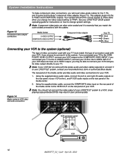
... lead TV SENSOR IR EMITTER SERIAL DATA 33V DC POWER 1.1A RECORD TAPE AUX VCR TV AM L L L L L FM 75 ANTENNA 1 OPTICAL OPTICAL R R R R R VIDEO INPUTS COMPOSITE S-VIDEO 2 SPEAKER ZONES INPUT OUTPUT DIGITAL AUDIO OUTPUTS DIGITAL DIGITAL DIGITAL AUDIO INPUTS DIGITAL COMPOSITE S-VIDEO VIDEO OUTPUTS Connecting an FM antenna Plug the connector on the FM dipole antenna lead into the AM antenna jack. 2. Connecting to a cable radio provider Some cable TV providers make FM radio signals available through the cable service to ensure the best reception. Move the AM loop...
... lead TV SENSOR IR EMITTER SERIAL DATA 33V DC POWER 1.1A RECORD TAPE AUX VCR TV AM L L L L L FM 75 ANTENNA 1 OPTICAL OPTICAL R R R R R VIDEO INPUTS COMPOSITE S-VIDEO 2 SPEAKER ZONES INPUT OUTPUT DIGITAL AUDIO OUTPUTS DIGITAL DIGITAL DIGITAL AUDIO INPUTS DIGITAL COMPOSITE S-VIDEO VIDEO OUTPUTS Connecting an FM antenna Plug the connector on the FM dipole antenna lead into the AM antenna jack. 2. Connecting to a cable radio provider Some cable TV providers make FM radio signals available through the cable service to ensure the best reception. Move the AM loop...
Installation guide
Page 16
...S-VIDEO 2 SPEAKER ZONES INPUT OUTPUT DIGITAL AUDIO OUTPUTS DIGITAL DIGITAL DIGITAL AUDIO INPUTS DIGITAL COMPOSITE S-VIDEO VIDEO OUTPUTS VCR connector panel AUDIO OUT VIDEO OUT R L VCR 16 AM259777_02_V.pdf • April 23, 2002 Your system will need video-grade cables for your LIFESTYLE ® system to a VCR, since playing copy-protected DVDs may be able to connect your VCR composite video output directly to your VCR does not have an S-VIDEO output, you change system settings. This adapter plugs into the S-VIDEO and COMPOSITE outputs. System Installation Instructions...
...S-VIDEO 2 SPEAKER ZONES INPUT OUTPUT DIGITAL AUDIO OUTPUTS DIGITAL DIGITAL DIGITAL AUDIO INPUTS DIGITAL COMPOSITE S-VIDEO VIDEO OUTPUTS VCR connector panel AUDIO OUT VIDEO OUT R L VCR 16 AM259777_02_V.pdf • April 23, 2002 Your system will need video-grade cables for your LIFESTYLE ® system to a VCR, since playing copy-protected DVDs may be able to connect your VCR composite video output directly to your VCR does not have an S-VIDEO output, you change system settings. This adapter plugs into the S-VIDEO and COMPOSITE outputs. System Installation Instructions...

Installation guide
Page 19
... the Acoustimass module Connector panel AUDIO INPUT L C R FRONT Power switch OUTPUTS TO CUBE SPEAKERS SURROUND L R POWER 100-120/200-240V AC 50/60 Hz 350W MAX. 19 AM259777_02_V.pdf • April 23, 2002 Plug the small end of the media center (Figure 17). Turn the Acoustimass module POWER switch to on the rear of the Acoustimass® module power cord into the AC power jack on page 21. System Installation Instructions Making the temporary headset connection before connecting to power Plug the special headset connector into the AUX jacks...
... the Acoustimass module Connector panel AUDIO INPUT L C R FRONT Power switch OUTPUTS TO CUBE SPEAKERS SURROUND L R POWER 100-120/200-240V AC 50/60 Hz 350W MAX. 19 AM259777_02_V.pdf • April 23, 2002 Plug the small end of the media center (Figure 17). Turn the Acoustimass module POWER switch to on the rear of the Acoustimass® module power cord into the AC power jack on page 21. System Installation Instructions Making the temporary headset connection before connecting to power Plug the special headset connector into the AUX jacks...

Installation guide
Page 23
... system Left front speaker Center front Right front speaker speaker Acoustimass® module Front speaker outputs Rear speaker outputs Speaker zone 1 output Media center Left surround Right surround speaker speaker AUX left & right audio (if available) VCR left & right audio VCR video Cable TV or satellite input Cable/satellite box Cable TV or satellite video VCR Cable TV video Video output TV TV power detector TM 23 AM259777_02_V.pdf • April 23, 2002 Figure 22 Diagram of the media center as in Figure 1 on to your LIFESTYLE® home entertainment system. To play...
... system Left front speaker Center front Right front speaker speaker Acoustimass® module Front speaker outputs Rear speaker outputs Speaker zone 1 output Media center Left surround Right surround speaker speaker AUX left & right audio (if available) VCR left & right audio VCR video Cable TV or satellite input Cable/satellite box Cable TV or satellite video VCR Cable TV video Video output TV TV power detector TM 23 AM259777_02_V.pdf • April 23, 2002 Figure 22 Diagram of the media center as in Figure 1 on to your LIFESTYLE® home entertainment system. To play...

Installation guide
Page 24
... front speaker Center front Right front speaker speaker Acoustimass® module Front speaker outputs Rear speaker outputs Speaker zone 1 output Media center Left surround Right surround speaker speaker AUX left & right audio (if available) Input from cable provider Cable/satellite box VCR video VCR left & right audio VCR TV left & right audio TV Video output TV power detector 24 AM259777_02_V.pdf • April 23, 2002 Reference Figure 23 Diagram of a typical system To play TV audio through your system with VCR audio fed to the TV Connect the VCR audio outputs...
... front speaker Center front Right front speaker speaker Acoustimass® module Front speaker outputs Rear speaker outputs Speaker zone 1 output Media center Left surround Right surround speaker speaker AUX left & right audio (if available) Input from cable provider Cable/satellite box VCR video VCR left & right audio VCR TV left & right audio TV Video output TV power detector 24 AM259777_02_V.pdf • April 23, 2002 Reference Figure 23 Diagram of a typical system To play TV audio through your system with VCR audio fed to the TV Connect the VCR audio outputs...
Installation guide
Page 25
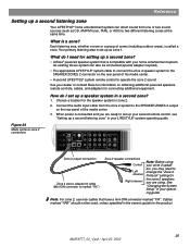
... appropriate LIFESTYLE® system cable to connect the zone 2 speaker system to the SPEAKER ZONES 2 connector on the rear panel of the media center. • A second LIFESTYLE® system remote control to the SPEAKER ZONES 2 output on obtaining additional powered speakers, remote controls, cables, and adapters for setting up a second zone? • A Bose® powered speaker system that have a mini-DIN connector marked "FIX". An existing stereo system can direct sound from the zone 2 system to operate the zone 2 sound. What is called a zone. See "Changing the System Setup...
... appropriate LIFESTYLE® system cable to connect the zone 2 speaker system to the SPEAKER ZONES 2 connector on the rear panel of the media center. • A second LIFESTYLE® system remote control to the SPEAKER ZONES 2 output on obtaining additional powered speakers, remote controls, cables, and adapters for setting up a second zone? • A Bose® powered speaker system that have a mini-DIN connector marked "FIX". An existing stereo system can direct sound from the zone 2 system to operate the zone 2 sound. What is called a zone. See "Changing the System Setup...


