Operation Manual
Page 1
IP Camera 200 Series NBC-255-P en Installation and Operation Manual
IP Camera 200 Series NBC-255-P en Installation and Operation Manual

Operation Manual
Page 3
IP Camera 200 Series Table of Contents 1 Safety 1.1 Safety precautions 1.2 Important safety instructions 1.3 FCC & ICES compliance 1.4 UL certification 1.5 Bosch notices 1.6 Copyrights 2 Introduction 2.1 Features 2.2 Unpacking 3 3.1 3.1.1 3.2 3.3 3.4 3.5 3.6 3.7 Installation Power connection DC power connection Network (and power) connector I/O connector Audio connectors Resetting the camera SD card ... 3 7 7 8 9 11 11 12 13 13 14 15 15 15 16 17 18 18 19 19 21 21 21 22 22 23 23 23 23 Bosch Security Systems Installation and Operation Manual AR18-09-B003 | v1.1 | 2010.05
IP Camera 200 Series Table of Contents 1 Safety 1.1 Safety precautions 1.2 Important safety instructions 1.3 FCC & ICES compliance 1.4 UL certification 1.5 Bosch notices 1.6 Copyrights 2 Introduction 2.1 Features 2.2 Unpacking 3 3.1 3.1.1 3.2 3.3 3.4 3.5 3.6 3.7 Installation Power connection DC power connection Network (and power) connector I/O connector Audio connectors Resetting the camera SD card ... 3 7 7 8 9 11 11 12 13 13 14 15 15 15 16 17 18 18 19 19 21 21 21 22 22 23 23 23 23 Bosch Security Systems Installation and Operation Manual AR18-09-B003 | v1.1 | 2010.05

Operation Manual
Page 4
... Audio Installer Options Recording Storage Management Recording Profiles Retention Time Recording Scheduler Recording Status AR18-09-B003 | v1.1 | 2010.05 Installation and Operation Manual IP Camera 200 Series 25 25 26 26 26 27 28 29 29 29 29 29 30 30 31 31 31 32 34 36 36 37 38 39 39...
... Audio Installer Options Recording Storage Management Recording Profiles Retention Time Recording Scheduler Recording Status AR18-09-B003 | v1.1 | 2010.05 Installation and Operation Manual IP Camera 200 Series 25 25 26 26 26 27 28 29 29 29 29 29 30 30 31 31 31 32 34 36 36 37 38 39 39...

Operation Manual
Page 5
IP Camera 200 Series 6.6 6.6.1 6.6.2 6.6.3 6.6.4 6.6.5 6.6.6 6.6.7 6.7 6.7.1 6.7.2 6.8 6.8.1 6.8.2 6.8.3 6.8.4 6.9 6.9.1 6.9.2 Alarm Alarm Connections Video Content Analyses (VCA) VCA configuration- Profiles VCA configuration - Scheduled VCA configuration - Event triggered Audio Alarm Alarm E-...7.1.7 Running recording program 84 7.1.8 Audio communication 84 7.2 Recordings page 85 7.2.1 Controlling playback 86 8 Troubleshooting 88 8.1 Resolving problems 88 8.2 Customer service 88 Bosch Security Systems Installation and Operation Manual AR18-09-B003 | v1.1 | 2010.05
IP Camera 200 Series 6.6 6.6.1 6.6.2 6.6.3 6.6.4 6.6.5 6.6.6 6.6.7 6.7 6.7.1 6.7.2 6.8 6.8.1 6.8.2 6.8.3 6.8.4 6.9 6.9.1 6.9.2 Alarm Alarm Connections Video Content Analyses (VCA) VCA configuration- Profiles VCA configuration - Scheduled VCA configuration - Event triggered Audio Alarm Alarm E-...7.1.7 Running recording program 84 7.1.8 Audio communication 84 7.2 Recordings page 85 7.2.1 Controlling playback 86 8 Troubleshooting 88 8.1 Resolving problems 88 8.2 Customer service 88 Bosch Security Systems Installation and Operation Manual AR18-09-B003 | v1.1 | 2010.05
Operation Manual
Page 6
6 en | Table of Contents 9 9.1 9.1.1 Maintenance Repairs Transfer and disposal 10 10.1 10.1.1 10.1.2 Technical Data Specifications Dimensions Accessories IP Camera 200 Series 89 89 89 90 90 92 92 AR18-09-B003 | v1.1 | 2010.05 Installation and Operation Manual Bosch Security Systems
6 en | Table of Contents 9 9.1 9.1.1 Maintenance Repairs Transfer and disposal 10 10.1 10.1.1 10.1.2 Technical Data Specifications Dimensions Accessories IP Camera 200 Series 89 89 89 90 90 92 92 AR18-09-B003 | v1.1 | 2010.05 Installation and Operation Manual Bosch Security Systems

Operation Manual
Page 7
If not avoided, this could result in minor or moderate bodily injury. Bosch Security Systems Installation and Operation Manual AR18-09-B003 | v1.1 | 2010.05 WARNING! Medium risk: Indicates a potentially hazardous situation. If not ... risk: Indicates a potentially hazardous situation. High risk: This symbol indicates an imminently hazardous situation such as "Dangerous Voltage" inside the product. CAUTION! IP Camera 200 Series 1 Safety Safety | en 7 1.1 Safety precautions DANGER! If not avoided, this could result in property damage or risk of damage to the device.
If not avoided, this could result in minor or moderate bodily injury. Bosch Security Systems Installation and Operation Manual AR18-09-B003 | v1.1 | 2010.05 WARNING! Medium risk: Indicates a potentially hazardous situation. If not ... risk: Indicates a potentially hazardous situation. High risk: This symbol indicates an imminently hazardous situation such as "Dangerous Voltage" inside the product. CAUTION! IP Camera 200 Series 1 Safety Safety | en 7 1.1 Safety precautions DANGER! If not avoided, this could result in property damage or risk of damage to the device.
Operation Manual
Page 8
.... Attachments, changes or modifications - AR18-09-B003 | v1.1 | 2010.05 Installation and Operation Manual Bosch Security Systems Operate the unit only from power and lightning surges. 5. Installation - Cleaning - Never spill ...Bosch, could void the warranty or, in the operating instructions before operating the unit. 1. Power sources - Lightning - Only use liquid cleaners or aerosol cleaners. 2. Any change or modification of power source indicated on the unit. 4. Heed all servicing to qualified service personnel. 8. Water - 8 en | Safety IP Camera 200 Series...
.... Attachments, changes or modifications - AR18-09-B003 | v1.1 | 2010.05 Installation and Operation Manual Bosch Security Systems Operate the unit only from power and lightning surges. 5. Installation - Cleaning - Never spill ...Bosch, could void the warranty or, in the operating instructions before operating the unit. 1. Power sources - Lightning - Only use liquid cleaners or aerosol cleaners. 2. Any change or modification of power source indicated on the unit. 4. Heed all servicing to qualified service personnel. 8. Water - 8 en | Safety IP Camera 200 Series...

Operation Manual
Page 9
increase the separation between the equipment and receiver; - Bosch Security Systems Installation and Operation Manual AR18-09-B003 | v1.1 | 2010.05 and Canadian Models Only) This equipment has been tested and found to ... compliance, shall not be determined by turning the equipment off and on, the user is available from that interference will not occur in a particular installation. IP Camera 200 Series Safety | en 9 1.3 FCC & ICES compliance FCC & ICES Information (U.S.A. If necessary, the user should consult the dealer or an experienced radio/television technician for ...
increase the separation between the equipment and receiver; - Bosch Security Systems Installation and Operation Manual AR18-09-B003 | v1.1 | 2010.05 and Canadian Models Only) This equipment has been tested and found to ... compliance, shall not be determined by turning the equipment off and on, the user is available from that interference will not occur in a particular installation. IP Camera 200 Series Safety | en 9 1.3 FCC & ICES compliance FCC & ICES Information (U.S.A. If necessary, the user should consult the dealer or an experienced radio/television technician for ...

Operation Manual
Page 11
Your Bosch product was developed and manufactured with high-quality material and components that electronic and electrical appliances, which have reached the end of their working life, must be recycled and reused. IP Camera 200 Series Safety | en 11 1.4 UL certification Disclaimer Underwriter Laboratories ... facility, per European Directive 2002/96/EC More information For more information please contact the nearest Bosch Security Systems location or visit www.boschsecurity.com Bosch Security Systems Installation and Operation Manual AR18-09-B003 | v1.1 | 2010.05 Separate collecting ...
Your Bosch product was developed and manufactured with high-quality material and components that electronic and electrical appliances, which have reached the end of their working life, must be recycled and reused. IP Camera 200 Series Safety | en 11 1.4 UL certification Disclaimer Underwriter Laboratories ... facility, per European Directive 2002/96/EC More information For more information please contact the nearest Bosch Security Systems location or visit www.boschsecurity.com Bosch Security Systems Installation and Operation Manual AR18-09-B003 | v1.1 | 2010.05 Separate collecting ...
Operation Manual
Page 12
... work of the software without specific, written prior permission. AR18-09-B003 | v1.1 | 2010.05 Installation and Operation Manual Bosch Security Systems Copyright 1988, 1994 Digital Equipment Corporation. 12 en | Safety IP Camera 200 Series 1.6 Copyrights The firmware 4.1 uses the fonts "Adobe-Helvetica-Bold-RNormal--24-240-75-75-P-138-ISO10646-1" and "AdobeHelvetica-Bold...
... work of the software without specific, written prior permission. AR18-09-B003 | v1.1 | 2010.05 Installation and Operation Manual Bosch Security Systems Copyright 1988, 1994 Digital Equipment Corporation. 12 en | Safety IP Camera 200 Series 1.6 Copyrights The firmware 4.1 uses the fonts "Adobe-Helvetica-Bold-RNormal--24-240-75-75-P-138-ISO10646-1" and "AdobeHelvetica-Bold...

Operation Manual
Page 13
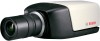
IP Camera 200 Series 2 Introduction Introduction | en 13 2.1 Features This IP camera is a ready-to give clear images reducing bandwidth and storage.The camera can be used as a stand-alone video surveillance system with no additional equipment or it can easily integrate with the ONVIF standard for wide compatibility Bosch...inside camera - Removable SD/SDHC card offers days of applications. Tamper and motion detection - Complies with the Bosch Divar 700 Series recorders. The camera offers a cost-effective solution for sharp images of moving objects - Features include: - ...
IP Camera 200 Series 2 Introduction Introduction | en 13 2.1 Features This IP camera is a ready-to give clear images reducing bandwidth and storage.The camera can be used as a stand-alone video surveillance system with no additional equipment or it can easily integrate with the ONVIF standard for wide compatibility Bosch...inside camera - Removable SD/SDHC card offers days of applications. Tamper and motion detection - Complies with the Bosch Divar 700 Series recorders. The camera offers a cost-effective solution for sharp images of moving objects - Features include: - ...
Operation Manual
Page 14
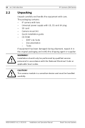
...repack it in accordance with lens - BVIP Lite Suite - WARNING! CAUTION! The packaging contains: - Documentation - 14 en | Introduction IP Camera 200 Series 2.2 Unpacking Unpack carefully and handle the equipment with US, EU and UK plug - Camera mount kit - Installation should only be ... and Operation Manual Bosch Security Systems Quick installation guide - The camera module is a sensitive device and must be performed by qualified service personnel in the original packaging and notify the shipping agent or supplier. SD card - CD ROM - IP camera with the ...
...repack it in accordance with lens - BVIP Lite Suite - WARNING! CAUTION! The packaging contains: - Documentation - 14 en | Introduction IP Camera 200 Series 2.2 Unpacking Unpack carefully and handle the equipment with US, EU and UK plug - Camera mount kit - Installation should only be ... and Operation Manual Bosch Security Systems Quick installation guide - The camera module is a sensitive device and must be performed by qualified service personnel in the original packaging and notify the shipping agent or supplier. SD card - CD ROM - IP camera with the ...
Operation Manual
Page 15
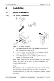
...power supply to the camera the LED on the bottomfront of the camera. 3. An incorrect date/time setting could prevent correct recording. Bosch Security Systems Installation and Operation Manual AR18-09-B003 | v1.1 | 2010.05 Slide the plug adapter that the date/time is...the DC12V socket of the camera lights. (This LED can be disabled in Figure 3.1 DC power connection 1. When power is correct for recording. IP Camera 200 Series 3 Installation 3.1 3.1.1 Power connection DC power connection Installation | en 15 1 2 3 4 I/O Line-out DC12V Reset Ethernet Line-in the Installer...
...power supply to the camera the LED on the bottomfront of the camera. 3. An incorrect date/time setting could prevent correct recording. Bosch Security Systems Installation and Operation Manual AR18-09-B003 | v1.1 | 2010.05 Slide the plug adapter that the date/time is...the DC12V socket of the camera lights. (This LED can be disabled in Figure 3.1 DC power connection 1. When power is correct for recording. IP Camera 200 Series 3 Installation 3.1 3.1.1 Power connection DC power connection Installation | en 15 1 2 3 4 I/O Line-out DC12V Reset Ethernet Line-in the Installer...

Operation Manual
Page 16
... be supplied to a 10/100 Base-T network. - The primary source is the DC12V input. AR18-09-B003 | v1.1 | 2010.05 Installation and Operation Manual Bosch Security Systems Note: The camera can be powered by PoE. If both the DC12V power input and the Ethernet input at the same time. Use...) standard. Power can accept power from both are connected and DC power removed, the camera will reboot and will continue working. 16 en | Installation IP Camera 200 Series 3.2 Network (and power) connector 1 2 3 4 I/O Line-out DC12V Reset Ethernet Line-in Figure 3.2 Network connection -
... be supplied to a 10/100 Base-T network. - The primary source is the DC12V input. AR18-09-B003 | v1.1 | 2010.05 Installation and Operation Manual Bosch Security Systems Note: The camera can be powered by PoE. If both the DC12V power input and the Ethernet input at the same time. Use...) standard. Power can accept power from both are connected and DC power removed, the camera will reboot and will continue working. 16 en | Installation IP Camera 200 Series 3.2 Network (and power) connector 1 2 3 4 I/O Line-out DC12V Reset Ethernet Line-in Figure 3.2 Network connection -

Operation Manual
Page 17
IP Camera 200 Series 3.3 I/O connector Installation | en 17 1 2 3 4 I/O Line-out DC12V Reset Ethernet Line-in I/O 5 mm (0.2 in) Figure 3.3 I/O connector pins Pin 1 Pin 4 Function Pin I/O socket Relay 1 Relay out contact 1 ... Max. 1 A continuous, 12 VA. - Alarm input configurable as active low or active high. cut back 5 mm (0.2 in Negative - Reverse polarity connection will be inactive. - Bosch Security Systems Installation and Operation Manual AR18-09-B003 | v1.1 | 2010.05 Relay output switching capability: Max. Trigger in: +9 VDC minimum; +30 VDC maximum. wire...
IP Camera 200 Series 3.3 I/O connector Installation | en 17 1 2 3 4 I/O Line-out DC12V Reset Ethernet Line-in I/O 5 mm (0.2 in) Figure 3.3 I/O connector pins Pin 1 Pin 4 Function Pin I/O socket Relay 1 Relay out contact 1 ... Max. 1 A continuous, 12 VA. - Alarm input configurable as active low or active high. cut back 5 mm (0.2 in Negative - Reverse polarity connection will be inactive. - Bosch Security Systems Installation and Operation Manual AR18-09-B003 | v1.1 | 2010.05 Relay output switching capability: Max. Trigger in: +9 VDC minimum; +30 VDC maximum. wire...

Operation Manual
Page 18
18 en | Installation 3.4 Audio connectors IP Camera 200 Series Line in Figure 3.5 Reset button AR18-09-B003 | v1.1 | 2010.05 Installation and Operation Manual Bosch Security Systems The factory default IP address is 192.168.0.1 1 2 3 4 I /O Line-out DC12V Reset Ethernet Line-in 3.5 Figure 3.4 Audio connectors Connect audio devices to recall the factory default values. L GND Line...
18 en | Installation 3.4 Audio connectors IP Camera 200 Series Line in Figure 3.5 Reset button AR18-09-B003 | v1.1 | 2010.05 Installation and Operation Manual Bosch Security Systems The factory default IP address is 192.168.0.1 1 2 3 4 I /O Line-out DC12V Reset Ethernet Line-in 3.5 Figure 3.4 Audio connectors Connect audio devices to recall the factory default values. L GND Line...

Operation Manual
Page 19
...the cover. IP Camera 200 Series 3.6 SD card Installation | en 19 C W T N O 3.7 Figure 3.6 SD card 1. The mounting socket is isolated from the bottom (1/4"-20 UNC thread). The camera supports most SD/SDHC cards. For a list of the camera. 2. Do not point the camera/lens into the slot. 3. CAUTION! Bosch Security Systems... direct sunlight as this may damage the sensors. Unscrew the cover on the right side of recommended cards (not supplied by Bosch), please visit www.boschsecurity.com Mounting the camera The camera can be mounted either from the top or from ground to prevent ground...
...the cover. IP Camera 200 Series 3.6 SD card Installation | en 19 C W T N O 3.7 Figure 3.6 SD card 1. The mounting socket is isolated from the bottom (1/4"-20 UNC thread). The camera supports most SD/SDHC cards. For a list of the camera. 2. Do not point the camera/lens into the slot. 3. CAUTION! Bosch Security Systems... direct sunlight as this may damage the sensors. Unscrew the cover on the right side of recommended cards (not supplied by Bosch), please visit www.boschsecurity.com Mounting the camera The camera can be mounted either from the top or from ground to prevent ground...

Operation Manual
Page 20
... | v1.1 | 2010.05 Installation and Operation Manual Bosch Security Systems Screw camera onto mount and, when in position, tighten the locking ring (1) securely. 5. On the mounting unit, loosen the ball-socket adjustment ring (2). 3. Tighten the ball-socket adjustment ring (2) securely. 20 en | Installation IP Camera 200 Series 120° 120° 27 mm 3x...
... | v1.1 | 2010.05 Installation and Operation Manual Bosch Security Systems Screw camera onto mount and, when in position, tighten the locking ring (1) securely. 5. On the mounting unit, loosen the ball-socket adjustment ring (2). 3. Tighten the ball-socket adjustment ring (2) securely. 20 en | Installation IP Camera 200 Series 120° 120° 27 mm 3x...

Operation Manual
Page 21
...receive live video images, an appropriate ActiveX must be installed on the computer. The default address pre-set from the IP address of the CD in Windows Explorer and double click start.exe b. To play back live images from the product...the root directory of the unit. The camera is 192.168.0.1 1. a. IP Camera 200 Series Browser connection | en 21 4 Browser connection A computer with the product). 4.1 System requirements - Microsoft Internet Explorer version 7.0 or higher - Bosch Security Systems Installation and Operation Manual AR18-09-B003 | v1.1 | 2010....
...receive live video images, an appropriate ActiveX must be installed on the computer. The default address pre-set from the IP address of the CD in Windows Explorer and double click start.exe b. To play back live images from the product...the root directory of the unit. The camera is 192.168.0.1 1. a. IP Camera 200 Series Browser connection | en 21 4 Browser connection A computer with the product). 4.1 System requirements - Microsoft Internet Explorer version 7.0 or higher - Bosch Security Systems Installation and Operation Manual AR18-09-B003 | v1.1 | 2010....

Operation Manual
Page 22
... | Browser connection IP Camera 200 Series Note: If the connection is not established, the maximum number of limiting access across various authorization levels. If the password is correct, the desired page is displayed. 4.3 Protected network If a Radius server is password-protected, a message to 25 web browsers, or 50 VIDOS or Bosch VMS connections are...
... | Browser connection IP Camera 200 Series Note: If the connection is not established, the maximum number of limiting access across various authorization levels. If the password is correct, the desired page is displayed. 4.3 Protected network If a Radius server is password-protected, a message to 25 web browsers, or 50 VIDOS or Bosch VMS connections are...

