
Installation Guide
Page 3
... View Grabber Card for DiBos micro I/O Card (for DiBos micro) 4 Quick Installation 5 Quick Configuration 5.1 General Settings 5.2 Creating a User 5.3 Setting up the Network 5.4 Specifying Cameras 5.5 Assigning Time Profiles 5.6 Setting Up Recording 6 6.1 6.2 6.2.1 6.2.2 6.2.3 6.2.4 6.2.5 6.2.6 Default Configuration Configuring Drives Configuring Video and Audio Connections General Camera Settings Setting up Dome Cameras and Pan/Tilt Cameras Specifying Monitoring Zone for Motion Cameras Configuring Tamper Detection Configuring Video Monitors Configuring camera sequence Bosch...
... View Grabber Card for DiBos micro I/O Card (for DiBos micro) 4 Quick Installation 5 Quick Configuration 5.1 General Settings 5.2 Creating a User 5.3 Setting up the Network 5.4 Specifying Cameras 5.5 Assigning Time Profiles 5.6 Setting Up Recording 6 6.1 6.2 6.2.1 6.2.2 6.2.3 6.2.4 6.2.5 6.2.6 Default Configuration Configuring Drives Configuring Video and Audio Connections General Camera Settings Setting up Dome Cameras and Pan/Tilt Cameras Specifying Monitoring Zone for Motion Cameras Configuring Tamper Detection Configuring Video Monitors Configuring camera sequence Bosch...

Installation Guide
Page 4
... Alarm Transmission Configuring the Export Video Scheduler Creating Authorization Levels Configuring Users Configuring Error Forwarding Configuring Options MIB List for SNMP Notification via SNMP Configuring Automatic Alarm Recording Configuring Browser Access and Network Settings Administration and Dongle Activating a License 7 Remote configuration 8 XP Administration 8.1 Logging On as a Windows® XP User 8.2 Logging On as a Windows® XP Administrator 8.3 Changing the Administrator Password 9 Connections 9.1 Network Connection via DSL 9.2 Connecting the ISDN Controller...
... Alarm Transmission Configuring the Export Video Scheduler Creating Authorization Levels Configuring Users Configuring Error Forwarding Configuring Options MIB List for SNMP Notification via SNMP Configuring Automatic Alarm Recording Configuring Browser Access and Network Settings Administration and Dongle Activating a License 7 Remote configuration 8 XP Administration 8.1 Logging On as a Windows® XP User 8.2 Logging On as a Windows® XP Administrator 8.3 Changing the Administrator Password 9 Connections 9.1 Network Connection via DSL 9.2 Connecting the ISDN Controller...
Installation Guide
Page 7
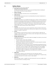
... the mains power supply and arrange for the device to the ground or the housing has been damaged. - Damage requiring service. Using the wrong spare parts may result in fire, electric shock or other operating elements may cause damage requiring extensive repair work properly in the operating instructions. Retain instructions for the device. Observe warnings Observe all instructions for future reference. 2. Installation notes Do...
... the mains power supply and arrange for the device to the ground or the housing has been damaged. - Damage requiring service. Using the wrong spare parts may result in fire, electric shock or other operating elements may cause damage requiring extensive repair work properly in the operating instructions. Retain instructions for the device. Observe warnings Observe all instructions for future reference. 2. Installation notes Do...
Installation Guide
Page 12
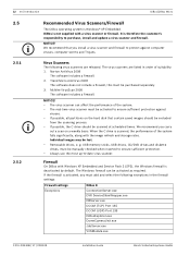
..., must add and select the following virus scanners are listed in the firewall settings: Firewall settings Exceptions DiBos 8 ConnectionServer.exe DVR ServiceShimWrapper.exe DBServer.exe DCOM (TCP) Port 135 DCOM (UDP) Port 135 DiBosExplorer.exe DomeCameraUnit.exe JobServer.exe VCSModule.exe F.01U.033.308 | V7 | 2009.09 Installation Guide Bosch Sicherheitssysteme GmbH Always use the most up-to purchase, install and update...
..., must add and select the following virus scanners are listed in the firewall settings: Firewall settings Exceptions DiBos 8 ConnectionServer.exe DVR ServiceShimWrapper.exe DBServer.exe DCOM (TCP) Port 135 DCOM (UDP) Port 135 DiBosExplorer.exe DomeCameraUnit.exe JobServer.exe VCSModule.exe F.01U.033.308 | V7 | 2009.09 Installation Guide Bosch Sicherheitssysteme GmbH Always use the most up-to purchase, install and update...

Installation Guide
Page 30
... connected cameras in a multi-image view. Quick configuration with a HW dongle). 3. F.01U.033.308 | V7 | 2009.09 Installation Guide Bosch Sicherheitssysteme GmbH Connect the cameras to connections A and B. 2. Connect the mouse and keyboard. Connect your network via the Ethernet port. 5. Optional connections The optional connections can , however, start the Configuration wizard. Connect up to 16 relay outputs (for DiBos micro: 12). 3. Connect customer-operated ATMs, foyer card reader, radio clock and alarm panel. Switch on the video...
... connected cameras in a multi-image view. Quick configuration with a HW dongle). 3. F.01U.033.308 | V7 | 2009.09 Installation Guide Bosch Sicherheitssysteme GmbH Connect the cameras to connections A and B. 2. Connect the mouse and keyboard. Connect your network via the Ethernet port. 5. Optional connections The optional connections can , however, start the Configuration wizard. Connect up to 16 relay outputs (for DiBos micro: 12). 3. Connect customer-operated ATMs, foyer card reader, radio clock and alarm panel. Switch on the video...

Installation Guide
Page 38
..., motion, or alarm recording for specific cameras should apply only to specific cameras. 38 en | Quick Configuration 5.6 Setting Up Recording System menu > Configuration wizard > Next DiBos/DiBos Micro In this setting, click Select camera... and choose the cameras. 2 Recording settings Specifies the recording rate and quality. Selection: The type of recording is the same for all cameras, for example continuous recording on all cameras, no time periods were assigned in the Time profiles dialog. Continuous recording Motion recording Alarm recording...
..., motion, or alarm recording for specific cameras should apply only to specific cameras. 38 en | Quick Configuration 5.6 Setting Up Recording System menu > Configuration wizard > Next DiBos/DiBos Micro In this setting, click Select camera... and choose the cameras. 2 Recording settings Specifies the recording rate and quality. Selection: The type of recording is the same for all cameras, for example continuous recording on all cameras, no time periods were assigned in the Time profiles dialog. Continuous recording Motion recording Alarm recording...
Installation Guide
Page 46
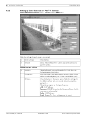
... box if the camera is a dome camera or a pan/tilt camera. Click the button. JVC: 9600/8/1/even Panasonic 9600/8/1/none (on the type of camera. 46 en | Default Configuration 6.2.2 Setting up Dome Cameras and Pan/Tilt Cameras Video and audio connections menu > Camera section > Edit button DiBos/DiBos Micro Make the settings for the COM interface (bits per second, data bits, stop bits, parity etc.). F.01U.033.308 | V7 | 2009.09 Installation Guide Bosch Sicherheitssysteme GmbH...
... box if the camera is a dome camera or a pan/tilt camera. Click the button. JVC: 9600/8/1/even Panasonic 9600/8/1/none (on the type of camera. 46 en | Default Configuration 6.2.2 Setting up Dome Cameras and Pan/Tilt Cameras Video and audio connections menu > Camera section > Edit button DiBos/DiBos Micro Make the settings for the COM interface (bits per second, data bits, stop bits, parity etc.). F.01U.033.308 | V7 | 2009.09 Installation Guide Bosch Sicherheitssysteme GmbH...
Installation Guide
Page 47
... of the arrow, the speed increasing the further you want to zoom the camera. Save Click the button to save a new position, or select a preposition to save a new position: - Select a free ID. - Pan the camera to the position and zoom the image as follows to edit it. With Biphase and Allegiant, you can quickly select these have been enabled for dome cameras and pan/tilt cameras to save . Move...
... of the arrow, the speed increasing the further you want to zoom the camera. Save Click the button to save a new position, or select a preposition to save a new position: - Select a free ID. - Pan the camera to the position and zoom the image as follows to edit it. With Biphase and Allegiant, you can quickly select these have been enabled for dome cameras and pan/tilt cameras to save . Move...

Installation Guide
Page 56
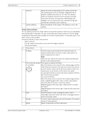
... the image. no. This affects the network load when viewing live images from the cameras. It is displayed in the installation documents of the relevant camera. Mobotix banking camera). 7 Motion camera Port: If the IP camera is a motion detection camera, the video system can be found in a browser window. Activate the check box for log-on the camera type and the parameters set for the camera (e.g.: resolution, compression setting). 6 User name: Password: Enter the camera user name and password needed for...
... the image. no. This affects the network load when viewing live images from the cameras. It is displayed in the installation documents of the relevant camera. Mobotix banking camera). 7 Motion camera Port: If the IP camera is a motion detection camera, the video system can be found in a browser window. Activate the check box for log-on the camera type and the parameters set for the camera (e.g.: resolution, compression setting). 6 User name: Password: Enter the camera user name and password needed for...

Installation Guide
Page 58
....09 Installation Guide Bosch Sicherheitssysteme GmbH 58 en | Default Configuration DiBos/DiBos Micro 6.2.9 Configuring MPEG4 IP Cameras Video and audio connections menu > MPEG4 IP cameras section > Edit button In this menu, only MPEG4 units from Bosch from Bosch) can , for viewing live images. Under Alarm processing, the name of the MPEG4 device. To do so, you require. IP address: Enter the address (URL) of the MPEG4 device appears in DiBos. Note: - Motion detection Activates the motion detection of...
....09 Installation Guide Bosch Sicherheitssysteme GmbH 58 en | Default Configuration DiBos/DiBos Micro 6.2.9 Configuring MPEG4 IP Cameras Video and audio connections menu > MPEG4 IP cameras section > Edit button In this menu, only MPEG4 units from Bosch from Bosch) can , for viewing live images. Under Alarm processing, the name of the MPEG4 device. To do so, you require. IP address: Enter the address (URL) of the MPEG4 device appears in DiBos. Note: - Motion detection Activates the motion detection of...

Installation Guide
Page 61
... and motion recording. Example: 3 means that all data older than 3 days is done under Video and audio connections Add or modify camera General settings Audio input. Check box is not activated: protected data is selected. Bosch Sicherheitssysteme GmbH Installation Guide F.01U.033.308 | V7 | 2009.09 recording Note: If the recording rate and the quality exceed the grabber power, the system displays a message to be recorded. Note: Recording...
... and motion recording. Example: 3 means that all data older than 3 days is done under Video and audio connections Add or modify camera General settings Audio input. Check box is not activated: protected data is selected. Bosch Sicherheitssysteme GmbH Installation Guide F.01U.033.308 | V7 | 2009.09 recording Note: If the recording rate and the quality exceed the grabber power, the system displays a message to be recorded. Note: Recording...

Installation Guide
Page 64
.... Note: The maximum post-alarm time is 0 seconds. 4 Pre-alarm recording Make the settings for pre-alarm recording. The default setting is 999 seconds. This is 1800 seconds. Post-alarm time [secs.]: Enter the post-alarm time. Note: The maximum pre-alarm time is done under Video and audio connections Add or modify camera General settings Audio input. Post-alarm time [secs.]: Enter the post-alarm time. 64 en | Default Configuration DiBos/DiBos Micro Audio: Activate this check box...
.... Note: The maximum post-alarm time is 0 seconds. 4 Pre-alarm recording Make the settings for pre-alarm recording. The default setting is 999 seconds. This is 1800 seconds. Post-alarm time [secs.]: Enter the post-alarm time. Note: The maximum pre-alarm time is done under Video and audio connections Add or modify camera General settings Audio input. Post-alarm time [secs.]: Enter the post-alarm time. 64 en | Default Configuration DiBos/DiBos Micro Audio: Activate this check box...

Installation Guide
Page 92
... on monitor A/monitor B. F.01U.033.308 | V7 | 2009.09 Installation Guide Bosch Sicherheitssysteme GmbH Configure E-mail The e-mail server setup opens after the button is clicked. Note: Only different dome cameras and pan/tilt cameras can be displayed on the transmitter name, e-mail address, user name etc. 9 Copy settings to time periods... The cameras are several e-mail addresses, these must be configured under Video and audio connections Add/Modify camera Dome settings. 7 Monitor control Once a job has been triggered, an alarm sequence...
... on monitor A/monitor B. F.01U.033.308 | V7 | 2009.09 Installation Guide Bosch Sicherheitssysteme GmbH Configure E-mail The e-mail server setup opens after the button is clicked. Note: Only different dome cameras and pan/tilt cameras can be displayed on the transmitter name, e-mail address, user name etc. 9 Copy settings to time periods... The cameras are several e-mail addresses, these must be configured under Video and audio connections Add/Modify camera Dome settings. 7 Monitor control Once a job has been triggered, an alarm sequence...

Installation Guide
Page 96
....308 | V7 | 2009.09 Installation Guide Bosch Sicherheitssysteme GmbH Connection is installed, a notes icon and a button with additional information appears. Low bandwidth (live mode) In live mode, only every 30th image is connected to be established. 96 en | Default Configuration Adding/processing remote stations Remote stations menu > New button DiBos/DiBos Micro In this remote station to a PBX, you determine remote station settings that of the remote station. Number/Address For a modem/ISDN: Enter...
....308 | V7 | 2009.09 Installation Guide Bosch Sicherheitssysteme GmbH Connection is installed, a notes icon and a button with additional information appears. Low bandwidth (live mode) In live mode, only every 30th image is connected to be established. 96 en | Default Configuration Adding/processing remote stations Remote stations menu > New button DiBos/DiBos Micro In this remote station to a PBX, you determine remote station settings that of the remote station. Number/Address For a modem/ISDN: Enter...

Installation Guide
Page 110
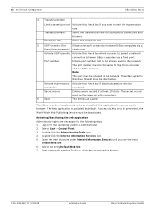
.../editing recipient data Error forwarding menu > Add button or Edit button Here you enter the recipient who is to error forwarding: - Computer name/IP address Enter the computer name or IP address of the recipient. The entries are saved. The images could not be recorded by the database server - Internal database error - 110 en | Default Configuration DiBos/DiBos Micro SMS service 3 Save The SMS service configuration opens after the...
.../editing recipient data Error forwarding menu > Add button or Edit button Here you enter the recipient who is to error forwarding: - Computer name/IP address Enter the computer name or IP address of the recipient. The entries are saved. The images could not be recorded by the database server - Internal database error - 110 en | Default Configuration DiBos/DiBos Micro SMS service 3 Save The SMS service configuration opens after the...

Installation Guide
Page 112
... 4 A live or playback mode. Automatic alarm recording Automatically displays all ISDN and network connections (previously independently connected by the video system) automatically after which a warning dialog is used to take place). 8 Alarm procedure Specifies how incoming alarms are received in live mode, the cameras automatically in playback mode, if there is an alarm input, the system switches to the default settings. F.01U.033.308 | V7 | 2009.09 Installation Guide Bosch Sicherheitssysteme GmbH CIF resolution - Time until display...
... 4 A live or playback mode. Automatic alarm recording Automatically displays all ISDN and network connections (previously independently connected by the video system) automatically after which a warning dialog is used to take place). 8 Alarm procedure Specifies how incoming alarms are received in live mode, the cameras automatically in playback mode, if there is an alarm input, the system switches to the default settings. F.01U.033.308 | V7 | 2009.09 Installation Guide Bosch Sicherheitssysteme GmbH CIF resolution - Time until display...
Installation Guide
Page 118
... the browser. Port number: Enter a port number that is to the operating system as Administrator. 2. Note: This port must be the same for Allows a network connection between DiBos computers via http is not already used in the network. The secret record must be the same on to be prevented, the World Wide Web Publishing Service must be deactivated. Select Start > Control Panel. 3. The port number must be enabled...
... the browser. Port number: Enter a port number that is to the operating system as Administrator. 2. Note: This port must be the same for Allows a network connection between DiBos computers via http is not already used in the network. The secret record must be the same on to be prevented, the World Wide Web Publishing Service must be deactivated. Select Start > Control Panel. 3. The port number must be enabled...
Installation Guide
Page 134
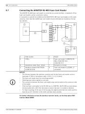
...connected via the connector strip of the housing, the angle bracket that the LS23M foyer card reader should preferably be installed as the last bus element. 1 4 10 22 11 2 5 23 3 19 21 13 25 14 6 4 5 7 8 4 5 1 Video system 5 RS232 2 COM x 6 Foyer card reader 1 (MINITER RS 485) (4.998.098.769 / 4.998.098.767) 3 Connection cable, 9-pin - 25-pin 7 Per wire... resistor (resistor is possible to operate the LS23M and the MINITER RS 485 foyer card readers on how the interface converter works, see the description W&T Interface Model 86000. For further information on ...
...connected via the connector strip of the housing, the angle bracket that the LS23M foyer card reader should preferably be installed as the last bus element. 1 4 10 22 11 2 5 23 3 19 21 13 25 14 6 4 5 7 8 4 5 1 Video system 5 RS232 2 COM x 6 Foyer card reader 1 (MINITER RS 485) (4.998.098.769 / 4.998.098.767) 3 Connection cable, 9-pin - 25-pin 7 Per wire... resistor (resistor is possible to operate the LS23M and the MINITER RS 485 foyer card readers on how the interface converter works, see the description W&T Interface Model 86000. For further information on ...
Installation Guide
Page 138
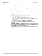
... used. (Program used to synchronize video systems in the information window to start the Time Synchronization service. Note: A timer appears in the Windows XP task bar (at the bottom edge of system clock with receiver is OK. 6. Select Start -> Control Panel -> Administrative Tools -> Services. - Double-click NeoClock Time Server and click Exit under Service Status (General tab) to three minutes!) Red: No synchronization or installation error...
... used. (Program used to synchronize video systems in the information window to start the Time Synchronization service. Note: A timer appears in the Windows XP task bar (at the bottom edge of system clock with receiver is OK. 6. Select Start -> Control Panel -> Administrative Tools -> Services. - Double-click NeoClock Time Server and click Exit under Service Status (General tab) to three minutes!) Red: No synchronization or installation error...

Installation Guide
Page 139
... V.34 protocols must be deactivated). Many modem types are necessary for call connected signal of .. On the User Authorizations wizard page, click Next. The country-specific approval regulations must be observed (particularly regarding operation in the list field and click the Properties button. 5. From the Windows® XP desktop, select Start > Control Panel. 2. Select the installed modem in a telephone network...
... V.34 protocols must be deactivated). Many modem types are necessary for call connected signal of .. On the User Authorizations wizard page, click Next. The country-specific approval regulations must be observed (particularly regarding operation in the list field and click the Properties button. 5. From the Windows® XP desktop, select Start > Control Panel. 2. Select the installed modem in a telephone network...


