

U8868 user's manual
Page 4
Chapter 1 Motherboard Description Notice Introduction of system This mainboard is designed to take advantage of its predecessors, this mainboard continues a commitment to provide you with PC Micro-... such as hard disks and CD-ROM Drives. 3.Supports the Intel Pentium ® 4 processor, a leading edge processor. Complies with the ultimate solution in data processing. U8868 Features: 1.Contains on board I/O facilities that include a serial port, a parallel port, a PS/2 mouse port, a PS/2 keyboard port, audio ports, USB ports and a game port. 2.Contains...
Chapter 1 Motherboard Description Notice Introduction of system This mainboard is designed to take advantage of its predecessors, this mainboard continues a commitment to provide you with PC Micro-... such as hard disks and CD-ROM Drives. 3.Supports the Intel Pentium ® 4 processor, a leading edge processor. Complies with the ultimate solution in data processing. U8868 Features: 1.Contains on board I/O facilities that include a serial port, a parallel port, a PS/2 mouse port, a PS/2 keyboard port, audio ports, USB ports and a game port. 2.Contains...

U8868 user's manual
Page 5
... the new generation power for x8 and 16 devices. 3.Max of 2 Double-Sided DDR SDRAM with unbuffered / Registered. 4.The largest memory capacity is 2 GB. 1-2 Chapter 1 Motherboard Description Mainboard Features 1. Super I/O Chipset - Features Introduction 1-1. Chipset: Chipset -
... the new generation power for x8 and 16 devices. 3.Max of 2 Double-Sided DDR SDRAM with unbuffered / Registered. 4.The largest memory capacity is 2 GB. 1-2 Chapter 1 Motherboard Description Mainboard Features 1. Super I/O Chipset - Features Introduction 1-1. Chipset: Chipset -
U8868 user's manual
Page 6
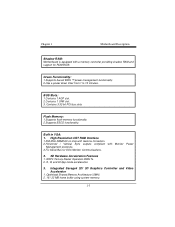
... RAM and support for DDC Monitor Communications. 2. 2D Hardware Acceleration Features 1. ROP3 Ternary Raster Operation BitBLTs. 2. 8, 16 and 32 bpp mode acceleration. 3. Chapter 1 Motherboard Description Shadow RAM: Motherboard is equipped with Monitor Power Management protocols. 3.I2C Serial Bus for ROM BIOS. Green Functionality: 1.Supports Award BIOS ™ power management functionality. 2.Has a power...
... RAM and support for DDC Monitor Communications. 2. 2D Hardware Acceleration Features 1. ROP3 Ternary Raster Operation BitBLTs. 2. 8, 16 and 32 bpp mode acceleration. 3. Chapter 1 Motherboard Description Shadow RAM: Motherboard is equipped with Monitor Power Management protocols. 3.I2C Serial Bus for ROM BIOS. Green Functionality: 1.Supports Award BIOS ™ power management functionality. 2.Has a power...

U8868 user's manual
Page 7
... 1. Alpha blending modes. 7. Massive 2K x 2K textures. 8. Reflection mapping, texture morphing, shadows, procedural textures and atmospheric effects. Microsoft Direct X texture compression. 9. MPEG-2 video textures. 9. Chapter 1 Motherboard Description 3. Single-pass multiple textures. 2. Built in IDE Facilities: 1.Supports four IDE hard disk drives. 2.Supports PIO Mode 4, Master Mode, and high performance hard disk...
... 1. Alpha blending modes. 7. Massive 2K x 2K textures. 8. Reflection mapping, texture morphing, shadows, procedural textures and atmospheric effects. Microsoft Direct X texture compression. 9. MPEG-2 video textures. 9. Chapter 1 Motherboard Description 3. Single-pass multiple textures. 2. Built in IDE Facilities: 1.Supports four IDE hard disk drives. 2.Supports PIO Mode 4, Master Mode, and high performance hard disk...

U8868 user's manual
Page 8
Enhanced Parallel Port (EPP). Dimensions (MATX form-factor): 24.5cm x 22.8cm (WxL) 1-5 Chapter 1 Motherboard Description AC'97 Sound Codec Onboard: 1.AC-LINK protocol comfliance. 2.Compliant with AC'97 specification. 3.18-bit full duplex stereo ADC, DACs. 4.SNR>95 Bb ...
Enhanced Parallel Port (EPP). Dimensions (MATX form-factor): 24.5cm x 22.8cm (WxL) 1-5 Chapter 1 Motherboard Description AC'97 Sound Codec Onboard: 1.AC-LINK protocol comfliance. 2.Compliant with AC'97 specification. 3.18-bit full duplex stereo ADC, DACs. 4.SNR>95 Bb ...

U8868 user's manual
Page 9
Operating System: Offers the highest performance for MATX Case (Optional). 6.Fully Setup Driver CD. 1-6 Package Contents 1.HDD Cable. 2.FDD Cable. 3.Flash Memory Writer for BIOS Update. 4.USB Cable (Optional). 5.Rear I/O Panel for MS-DOS, Windows NT, Windows 2000, Windows ME, Windows XP, Novell, LINUX, and SCO UNIX etc. 1-3. Chapter 1 Motherboard Description 1-2. BIOS & Software 1.Award legal BIOS. 2.Supports APM1.2. 3.Supports USB Function. 4.Supports ACPI.
Operating System: Offers the highest performance for MATX Case (Optional). 6.Fully Setup Driver CD. 1-6 Package Contents 1.HDD Cable. 2.FDD Cable. 3.Flash Memory Writer for BIOS Update. 4.USB Cable (Optional). 5.Rear I/O Panel for MS-DOS, Windows NT, Windows 2000, Windows ME, Windows XP, Novell, LINUX, and SCO UNIX etc. 1-3. Chapter 1 Motherboard Description 1-2. BIOS & Software 1.Award legal BIOS. 2.Supports APM1.2. 3.Supports USB Function. 4.Supports ACPI.

U8868 user's manual
Page 10
JPRNT1 JVGA1 J AT X P W R 2 VT8751 Game Port In Out MIC Line Speaker In 1612A 1 JCDIN1 BIOS 6103 AGP SLOT PCI SLOT PCI SLOT PCI1 JUSB4 2 10 2 10 1 91 9 JUSB3 PCI2 VT8235 BAT1 24 23 PCI SLOT CNR1 CNR SLOT PCI3 ITE 21 JPANEL1 JWOL1 1 JCMOS1 1 FLOPPY DISK CONN. 1-7 Chapter 1 Motherboard Description 2. SECONDARY IDE CONN. Mainboard Configuration 2-1. Layout of U8868 JKBMS1 K/B & Mouse 1 JLAN USB & LAN JCOM1 JKBV1 CPU1 Socket 478 CPU J AT X P W R 1 COM1 Parallel Port VGA1 PRIMARY IDE CONN.
JPRNT1 JVGA1 J AT X P W R 2 VT8751 Game Port In Out MIC Line Speaker In 1612A 1 JCDIN1 BIOS 6103 AGP SLOT PCI SLOT PCI SLOT PCI1 JUSB4 2 10 2 10 1 91 9 JUSB3 PCI2 VT8235 BAT1 24 23 PCI SLOT CNR1 CNR SLOT PCI3 ITE 21 JPANEL1 JWOL1 1 JCMOS1 1 FLOPPY DISK CONN. 1-7 Chapter 1 Motherboard Description 2. SECONDARY IDE CONN. Mainboard Configuration 2-1. Layout of U8868 JKBMS1 K/B & Mouse 1 JLAN USB & LAN JCOM1 JKBV1 CPU1 Socket 478 CPU J AT X P W R 1 COM1 Parallel Port VGA1 PRIMARY IDE CONN.

U8868 user's manual
Page 11
Chapter 1 Motherboard Description 2-2. Component Index 1-8
Chapter 1 Motherboard Description 2-2. Component Index 1-8

U8868 user's manual
Page 12
Locate Pin A in the socket and look for the white dot or cut edge then insert the CPU. 3. Match Pin A with the white dot/cut edge in the CPU. Press the lever down. CPU Configuration 3-1. CPU Socket 478 Configuration Steps: CPU Fan CPU 1. Pull the lever sideways away from the socket then raise the lever up to complete the installation. 1-9 Chapter 1 Motherboard Description 3. Then Put the fan on the CPU and buckle it and put the fan's power port into the JCFAN1, then to a 90-degree angle. 2.
Locate Pin A in the socket and look for the white dot or cut edge then insert the CPU. 3. Match Pin A with the white dot/cut edge in the CPU. Press the lever down. CPU Configuration 3-1. CPU Socket 478 Configuration Steps: CPU Fan CPU 1. Pull the lever sideways away from the socket then raise the lever up to complete the installation. 1-9 Chapter 1 Motherboard Description 3. Then Put the fan on the CPU and buckle it and put the fan's power port into the JCFAN1, then to a 90-degree angle. 2.

U8868 user's manual
Page 13
CPU Fan Header: JCFAN1 Pin No. 1 2 3 Assignment Ground +12V Sense 1-10 Chapter 1 Motherboard Description CPU Configuration Layout 3-2.
CPU Fan Header: JCFAN1 Pin No. 1 2 3 Assignment Ground +12V Sense 1-10 Chapter 1 Motherboard Description CPU Configuration Layout 3-2.

U8868 user's manual
Page 14
System Fan Header: JSFAN1 Pin No. 1 2 3 Assignment Ground +12V Sense 1-11 Chapter 1 Motherboard Description 3-3.
System Fan Header: JSFAN1 Pin No. 1 2 3 Assignment Ground +12V Sense 1-11 Chapter 1 Motherboard Description 3-3.

U8868 user's manual
Page 15
Chapter 1 Motherboard Description 4. Jumpers, Headers & Connectors JKBV1 1 JATXPWR2 JUSB3 2 10 1 9 JATXPWR1 IDE1-2 JUSB4 2 10 1 9 JPANEL1 JCMOS1 1 FDD1 JWOL1 1 1-12
Chapter 1 Motherboard Description 4. Jumpers, Headers & Connectors JKBV1 1 JATXPWR2 JUSB3 2 10 1 9 JATXPWR1 IDE1-2 JUSB4 2 10 1 9 JPANEL1 JCMOS1 1 FDD1 JWOL1 1 1-12

U8868 user's manual
Page 16
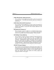
...the Power On Self-Test when the computer cannot use the video interface. This switch is not connected to a momentary SPST switch. Chapter 1 Motherboard Description 4-1. An offboard speaker can be connected to reset and run the POST (Power On Self Test). 1-13 Front Panel Connector: JPANEL1 ...20 KEY IrDA 21 VCC5 Connector 22 Ground Connector 23 IRTX 24 IRRX SPK (Speaker Connector) An offboard speaker can be installed on the motherboard as a manufacturing option. RST (Reset Button) This connector can be attached to the audio subsystem and does not receive output from the...
...the Power On Self-Test when the computer cannot use the video interface. This switch is not connected to a momentary SPST switch. Chapter 1 Motherboard Description 4-1. An offboard speaker can be connected to reset and run the POST (Power On Self Test). 1-13 Front Panel Connector: JPANEL1 ...20 KEY IrDA 21 VCC5 Connector 22 Ground Connector 23 IRTX 24 IRRX SPK (Speaker Connector) An offboard speaker can be installed on the motherboard as a manufacturing option. RST (Reset Button) This connector can be attached to the audio subsystem and does not receive output from the...
U8868 user's manual
Page 17
... is invoked by any keyboard activity, mouse activity, modem activity or when the sleep button is used to attach to internal debounce circuitry on . Chapter 1 Motherboard Description POW-LED (Power LED Connector) This connector can be attached to a front panel power switch.
... is invoked by any keyboard activity, mouse activity, modem activity or when the sleep button is used to attach to internal debounce circuitry on . Chapter 1 Motherboard Description POW-LED (Power LED Connector) This connector can be attached to a front panel power switch.

U8868 user's manual
Page 18
... 14 15 16 17 18 19 20 Assignment 3.3V -12V Ground PS_ON Ground Ground Ground -5V 5V 5V 4-3. You must be connected to IDE1. Chapter 1 Motherboard Description 4-2.
... 14 15 16 17 18 19 20 Assignment 3.3V -12V Ground PS_ON Ground Ground Ground -5V 5V 5V 4-3. You must be connected to IDE1. Chapter 1 Motherboard Description 4-2.
U8868 user's manual
Page 19
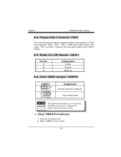
...: JCMOS1 JCMOS1 1 3 1-2 Closed 1 3 2-3 Closed Assignment Normal Operation (default) Clear CMOS Data The following procedures are for resetting the BIOS password. Floppy Disk Connector: FDD1 The motherboard provides a standard floppy disk connector (FDC) that supports 360K, 720K, 1.2M, 1.44M and 2.88M floppy disk types. Make JCMOS1 (2-3) closed. 1-16 Chapter...
...: JCMOS1 JCMOS1 1 3 1-2 Closed 1 3 2-3 Closed Assignment Normal Operation (default) Clear CMOS Data The following procedures are for resetting the BIOS password. Floppy Disk Connector: FDD1 The motherboard provides a standard floppy disk connector (FDC) that supports 360K, 720K, 1.2M, 1.44M and 2.88M floppy disk types. Make JCMOS1 (2-3) closed. 1-16 Chapter...

U8868 user's manual
Page 20
... Pin Assignment 2 +5V(fused) 4 USBP3- 6 USBP3+ 8 Ground 10 NC 4-8. Wait for KB: JKBV1 JKBV1 1 3 1-2 Closed 1 3 2-3 Closed Assignment 5V 5V_SB 1-17 Let AC power on. 6. Chapter 1 Motherboard Description 3.
... Pin Assignment 2 +5V(fused) 4 USBP3- 6 USBP3+ 8 Ground 10 NC 4-8. Wait for KB: JKBV1 JKBV1 1 3 1-2 Closed 1 3 2-3 Closed Assignment 5V 5V_SB 1-17 Let AC power on. 6. Chapter 1 Motherboard Description 3.

U8868 user's manual
Page 21
ATX 12V Power Connector: JATXPWR2 PIN 1 2 Assignment 12V 12V PIN 3 4 Assignment Ground Ground 1-18 Chapter 1 Motherboard Description 4-10.
ATX 12V Power Connector: JATXPWR2 PIN 1 2 Assignment 12V 12V PIN 3 4 Assignment Ground Ground 1-18 Chapter 1 Motherboard Description 4-10.

U8868 user's manual
Page 22
DDR SDRAM DRAM Access Time: 2.5V Unbuffered DDR SDRAM PC1600/ PC2100 Type required. Chapter 1 Motherboard Description 5. DRAM Type: 128MB/ 256MB/ 512MB/ 1GB DIMM Module (184 pin) Total Memory Size with unbuffer DIMMs (Only for reference) DIMM Socket Location DDR Module Total Memory Size (MB) DDR 1 64MB/128MB/256MB/512MB/1GB *1 Max is DDR 2 64MB/128MB/256MB/512MB/1GB 2GB *1 1-19 RAM Module Configuration 5-1.
DDR SDRAM DRAM Access Time: 2.5V Unbuffered DDR SDRAM PC1600/ PC2100 Type required. Chapter 1 Motherboard Description 5. DRAM Type: 128MB/ 256MB/ 512MB/ 1GB DIMM Module (184 pin) Total Memory Size with unbuffer DIMMs (Only for reference) DIMM Socket Location DDR Module Total Memory Size (MB) DDR 1 64MB/128MB/256MB/512MB/1GB *1 Max is DDR 2 64MB/128MB/256MB/512MB/1GB 2GB *1 1-19 RAM Module Configuration 5-1.

U8868 user's manual
Page 24
... definition are shown below: PS/2 Mouse / Keyboard Connectors Pin 1 2 3 4 5 6 Assignment Data No connect Ground +5 V (fused) Clock No connect 21 PS/2 Mouse / Keyboard Connector: JKBMS1 The motherboard provides a standard PS/2 mouse / Keyboard mini DIN connector for attaching a PS/2 mouse. Mainboard Features 6. Peripheral Port Features JKBMS1 PS/2 JUSBLAN1 Mouse LAN JPRNT1 Parallel JAUD_GAME...
... definition are shown below: PS/2 Mouse / Keyboard Connectors Pin 1 2 3 4 5 6 Assignment Data No connect Ground +5 V (fused) Clock No connect 21 PS/2 Mouse / Keyboard Connector: JKBMS1 The motherboard provides a standard PS/2 mouse / Keyboard mini DIN connector for attaching a PS/2 mouse. Mainboard Features 6. Peripheral Port Features JKBMS1 PS/2 JUSBLAN1 Mouse LAN JPRNT1 Parallel JAUD_GAME...

