Update Manual
Page 3
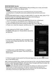
... lead to the USB port. 4. While the system boots up and the full screen logo shows up . Choose [fs0] to search for the motherboard. 2. Then, the BIOS Update is being continuously updated. The actual information and settings on or reset the computer and then press during the Power-...BIOS via USB pen drive. 1. All the information and content above are sure to flash the BIOS file. This utility only allows storage device with BIOSTAR BIOS Flasher 1. Insert the USB pen drive that contains the BIOS file to system boot failure. Press the [Y] key to restart system. 8. ...
... lead to the USB port. 4. While the system boots up and the full screen logo shows up . Choose [fs0] to search for the motherboard. 2. Then, the BIOS Update is being continuously updated. The actual information and settings on or reset the computer and then press during the Power-...BIOS via USB pen drive. 1. All the information and content above are sure to flash the BIOS file. This utility only allows storage device with BIOSTAR BIOS Flasher 1. Insert the USB pen drive that contains the BIOS file to system boot failure. Press the [Y] key to restart system. 8. ...

Setup Manual
Page 2
Table of Contents Chapter 1: Introduction 1 1.1 Before You Start 1 1.2 Package Checklist 1 1.3 Motherboard Features 2 1.4 Rear Panel Connectors 3 1.5 Motherboard Layout 4 Chapter 2: Hardware Installation 5 2.1 Installing Central Processing Unit (CPU 5 2.2 FAN Headers 7 2.3 Installing System Memory 8 2.4 Connectors and Slots 10 Chapter 3: Headers & Jumpers Setup 13 3.1 How to ...
Table of Contents Chapter 1: Introduction 1 1.1 Before You Start 1 1.2 Package Checklist 1 1.3 Motherboard Features 2 1.4 Rear Panel Connectors 3 1.5 Motherboard Layout 4 Chapter 2: Hardware Installation 5 2.1 Installing Central Processing Unit (CPU 5 2.2 FAN Headers 7 2.3 Installing System Memory 8 2.4 Connectors and Slots 10 Chapter 3: Headers & Jumpers Setup 13 3.1 How to ...

Setup Manual
Page 3
...Do not leave any safely grounded appliance, or use grounded wrist strap to remove the static charge. „ Avoid touching the components on motherboard or the rear side of the computer should be different due to 45 degrees Celsius. 1.2 PACKAGE CHECKLIST Serial ATA Cable X 4 Rear... I/O Panel for choosing our product. CHAPTER 1: INTRODUCTION TZ68K+ 1.1 BEFORE YOU START Thank you take the motherboard out from dangerous area, such as heat source, humid air and water. „ The operating temperatures of the board ...
...Do not leave any safely grounded appliance, or use grounded wrist strap to remove the static charge. „ Avoid touching the components on motherboard or the rear side of the computer should be different due to 45 degrees Celsius. 1.2 PACKAGE CHECKLIST Serial ATA Cable X 4 Rear... I/O Panel for choosing our product. CHAPTER 1: INTRODUCTION TZ68K+ 1.1 BEFORE YOU START Thank you take the motherboard out from dangerous area, such as heat source, humid air and water. „ The operating temperatures of the board ...

Setup Manual
Page 4
... Supports front panel audio function CPU Fan Header System Fan Header x1 CPU Fan power supply (with Smart Fan function) x2 System Fan Power supply 2 Motherboard Manual 1.3 MOTHERBOARD FEATURES SPEC CPU Chipset Socket 1155 Intel Core i7 / i5 / i3 / Pentium / Celeron processor Intel Z68 Supports Execute Disable Bit / Enhanced Intel SpeedStep®...
... Supports front panel audio function CPU Fan Header System Fan Header x1 CPU Fan power supply (with Smart Fan function) x2 System Fan Power supply 2 Motherboard Manual 1.3 MOTHERBOARD FEATURES SPEC CPU Chipset Socket 1155 Intel Core i7 / i5 / i3 / Pentium / Celeron processor Intel Z68 Supports Execute Disable Bit / Enhanced Intel SpeedStep®...
Setup Manual
Page 6
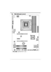
Motherboard Manual 1.5 MOTHERBOARD LAYOUT U SB_KBMS1 ATXPW R2 C PU_FAN1 HDMI1 DVI1 Socket 1155 CPU1 DDR3 _A1 DDR3 _A2 DDR3 _B1 DDR3 _B2 VGA1 RJ45USB 1 AUDIO1 SY S_FA N2 PEX16_1 ATXP WR1 LAN PEX1_1 Z68 BIOS CODEC PEX16_2 SATA2 SATA1 F_AU DIO1 BAT1 J CMOS1 Super I/O JSP DI FOUT1 J_PRINT1 PCI1 PCI2 J_C OM1 SY S_FA N1 SATA6 SATA5 SATA4 SATA3 LED_D2 LED_D1 SW_R ST1 CIR1 Note: ■ represents the 1st pin. F_USB3 F_USB2 F_USB1 PANEL1 SW_PWR1 4
Motherboard Manual 1.5 MOTHERBOARD LAYOUT U SB_KBMS1 ATXPW R2 C PU_FAN1 HDMI1 DVI1 Socket 1155 CPU1 DDR3 _A1 DDR3 _A2 DDR3 _B1 DDR3 _B2 VGA1 RJ45USB 1 AUDIO1 SY S_FA N2 PEX16_1 ATXP WR1 LAN PEX1_1 Z68 BIOS CODEC PEX16_2 SATA2 SATA1 F_AU DIO1 BAT1 J CMOS1 Super I/O JSP DI FOUT1 J_PRINT1 PCI1 PCI2 J_C OM1 SY S_FA N1 SATA6 SATA5 SATA4 SATA3 LED_D2 LED_D1 SW_R ST1 CIR1 Note: ■ represents the 1st pin. F_USB3 F_USB2 F_USB1 PANEL1 SW_PWR1 4

Setup Manual
Page 8
Motherboard Manual Step 3: Look for the triangular cut edge on socket, and the golden dot on the retention frame. Step 5: Put the CPU Fan and heatsink assembly on the CPU and buckle it on CPU should point forwards this triangular cut edge. The CPU will fit only in the correct orientation. Connect the CPU FAN power cable into the CPU_FAN1 to complete the installation. Step 4: Hold the CPU down firmly, and then lower the lever to locked position to complete the installation. 6
Motherboard Manual Step 3: Look for the triangular cut edge on socket, and the golden dot on the retention frame. Step 5: Put the CPU Fan and heatsink assembly on the CPU and buckle it on CPU should point forwards this triangular cut edge. The CPU will fit only in the correct orientation. Connect the CPU FAN power cable into the CPU_FAN1 to complete the installation. Step 4: Hold the CPU down firmly, and then lower the lever to locked position to complete the installation. 6

Setup Manual
Page 10
Memory Modules 1. Unlock a DIMM slot by pressing the retaining clips outward. Insert the DIMM vertically and firmly into the slot until the retaining chip snap back in place and the DIMM is properly seated. 8 DDR3_A1 DDR3_A2 DDR3_B1 DDR3_B2 Motherboard Manual 2.3 INSTALLING SYSTEM MEMORY A. Align a DIMM on the slot such that the notch on the DIMM matches the break on the Slot. 2.
Memory Modules 1. Unlock a DIMM slot by pressing the retaining clips outward. Insert the DIMM vertically and firmly into the slot until the retaining chip snap back in place and the DIMM is properly seated. 8 DDR3_A1 DDR3_A2 DDR3_B1 DDR3_B2 Motherboard Manual 2.3 INSTALLING SYSTEM MEMORY A. Align a DIMM on the slot such that the notch on the DIMM matches the break on the Slot. 2.

Setup Manual
Page 12
SATA5 SATA3 SATA6 SATA4 7 4 1 Pin Assignment 1 Ground 2 TX+ 3 TX4 Ground 5 RX6 RX+ 7 Ground 10 Motherboard Manual 2.4 CONNECTORS AND SLOTS SATA1/SATA2: Serial ATA3 Connectors The motherboard has a PCI to SATA Controller with 4 channels SATA2 interface, it satisfies the SATA 3.0 spec and with transfer rate of 6.0Gb/s. SATA2 SATA1 7 4 1 Pin Assignment 1 Ground 2 TX+ 3 TX4 Ground 5 RX6 RX+ 7 Ground SATA3~SATA6: Serial ATA2 Connectors The motherboard has a PCI to SATA Controller with 2 channels SATA3 interface, it satisfies the SATA 2.0 spec and with transfer rate of 3.0Gb/s.
SATA5 SATA3 SATA6 SATA4 7 4 1 Pin Assignment 1 Ground 2 TX+ 3 TX4 Ground 5 RX6 RX+ 7 Ground 10 Motherboard Manual 2.4 CONNECTORS AND SLOTS SATA1/SATA2: Serial ATA3 Connectors The motherboard has a PCI to SATA Controller with 4 channels SATA2 interface, it satisfies the SATA 3.0 spec and with transfer rate of 6.0Gb/s. SATA2 SATA1 7 4 1 Pin Assignment 1 Ground 2 TX+ 3 TX4 Ground 5 RX6 RX+ 7 Ground SATA3~SATA6: Serial ATA2 Connectors The motherboard has a PCI to SATA Controller with 2 channels SATA3 interface, it satisfies the SATA 2.0 spec and with transfer rate of 3.0Gb/s.

Setup Manual
Page 14
...up to 500MB/s per direction, for an aggregate of 16GB/s totally. - PEX16_ 1 PEX1_ 1 PEX16_ 2 PCI1/PCI2: Peripheral Component Interconnect Slot This motherboard is designated as 32 bits. PCI stands for Peripheral Component Interconnect, and it is a bus standard for an aggregate of 4GB/s totally. PCI-Express ...2.0 compliant. - PEX1_1: PCI-Express Gen2 x1 Slot - Motherboard Manual PEX16_1: PCI-Express Gen2 x16 Slot - PCI-Express Gen2 supports a raw bit-rate of 2.5Gb/s on the data pins. - 2X bandwidth ...
...up to 500MB/s per direction, for an aggregate of 16GB/s totally. - PEX16_ 1 PEX1_ 1 PEX16_ 2 PCI1/PCI2: Peripheral Component Interconnect Slot This motherboard is designated as 32 bits. PCI stands for Peripheral Component Interconnect, and it is a bus standard for an aggregate of 4GB/s totally. PCI-Express ...2.0 compliant. - PEX1_1: PCI-Express Gen2 x1 Slot - Motherboard Manual PEX16_1: PCI-Express Gen2 x16 Slot - PCI-Express Gen2 supports a raw bit-rate of 2.5Gb/s on the data pins. - 2X bandwidth ...

Setup Manual
Page 16
... in 10 Jack Sense 1 9 JSPDIFOUT1: Digital Audio-out Connector This connector allows user to connect the front audio output cable with the PC front panel. Motherboard Manual F_AUDIO1: Front Panel Audio Header This header allows user to connect the PCI bracket SPDIF output header.
... in 10 Jack Sense 1 9 JSPDIFOUT1: Digital Audio-out Connector This connector allows user to connect the front audio output cable with the PC front panel. Motherboard Manual F_AUDIO1: Front Panel Audio Header This header allows user to connect the PCI bracket SPDIF output header.

Setup Manual
Page 17
...- 4 USB- 5 USB+ 6 USB+ 7 Ground 8 Ground 9 Key 10 NC 1 9 15 Load Optimal Defaults and save settings in CMOS. TZ68K+ JCMOS1: Clear CMOS Header Placing the jumper on pin2-3 allows user to avoid damaging the motherboard. 13 Pin 1-2 Close: Normal Operation (default). 13 13 Pin 2-3 Close: Clear CMOS data. ※ Clear CMOS Procedures: 1. Set...
...- 4 USB- 5 USB+ 6 USB+ 7 Ground 8 Ground 9 Key 10 NC 1 9 15 Load Optimal Defaults and save settings in CMOS. TZ68K+ JCMOS1: Clear CMOS Header Placing the jumper on pin2-3 allows user to avoid damaging the motherboard. 13 Pin 1-2 Close: Normal Operation (default). 13 13 Pin 2-3 Close: Clear CMOS data. ※ Clear CMOS Procedures: 1. Set...

Setup Manual
Page 18
Motherboard Manual J_PRINT1: Printer Port Connector This header allows you to connector printer on the PC. 2 1 Pin Assignment 1 -Strobe 2 -ALF 3 Data 0 4 -Error 5 Data 1 6 -Init 7 Data 2 8 -Scltin 9 ... 17 Data 7 18 Ground 19 -ACK 20 Ground 21 Busy 22 Ground 23 PE 24 Ground 25 SCLT 26 Key J_COM1: Serial Port Connector The motherboard has a Serial Port Connector for connecting RS-232 Port. 2 10 1 9 Pin Assignment 1 Carrier detect 2 Received data 3 Transmitted data 4 Data terminal ready 5 Signal ground 6 Data set...
Motherboard Manual J_PRINT1: Printer Port Connector This header allows you to connector printer on the PC. 2 1 Pin Assignment 1 -Strobe 2 -ALF 3 Data 0 4 -Error 5 Data 1 6 -Init 7 Data 2 8 -Scltin 9 ... 17 Data 7 18 Ground 19 -ACK 20 Ground 21 Busy 22 Ground 23 PE 24 Ground 25 SCLT 26 Key J_COM1: Serial Port Connector The motherboard has a Serial Port Connector for connecting RS-232 Port. 2 10 1 9 Pin Assignment 1 Carrier detect 2 Received data 3 Transmitted data 4 Data terminal ready 5 Signal ground 6 Data set...

Setup Manual
Page 19
SW_RST1 17 SW_PWR1 SW_RST1: Reset button. TZ68K+ On-Board LED Indicators There are 2 on the motherboard showing system status. LED _D 2 LED _D 1 LED_D1 & LED_D2: Debug Indicators Please refer to the tables below for specific messages: LED_D1 LED_D2 Message ON ON OFF OFF ON Normal OFF Memory Error ON VGA Error OFF Abnormal: CPU / Chipset error. SW_PWR1: Power Switch button. On-Board Buttons There are 2 LED indicators on -board buttons.
SW_RST1 17 SW_PWR1 SW_RST1: Reset button. TZ68K+ On-Board LED Indicators There are 2 on the motherboard showing system status. LED _D 2 LED _D 1 LED_D1 & LED_D2: Debug Indicators Please refer to the tables below for specific messages: LED_D1 LED_D2 Message ON ON OFF OFF ON Normal OFF Memory Error ON VGA Error OFF Abnormal: CPU / Chipset error. SW_PWR1: Power Switch button. On-Board Buttons There are 2 LED indicators on -board buttons.

Setup Manual
Page 20
...: Does not deliver any drive in RAID 0 and RAID 1. It breaks up to 6 or 8. RAID 1: RAID 1 defines techniques for mirroring data. If any fault tolerance. Motherboard Manual CHAPTER 4: RAID FUNCTIONS 4.1 OPERATING SYSTEM Supports Windows Vista and Windows 7. 4.2 RAID ARRAYS RAID supports the following types of RAID arrays: RAID 0: RAID 0 defines a disk...
...: Does not deliver any drive in RAID 0 and RAID 1. It breaks up to 6 or 8. RAID 1: RAID 1 defines techniques for mirroring data. If any fault tolerance. Motherboard Manual CHAPTER 4: RAID FUNCTIONS 4.1 OPERATING SYSTEM Supports Windows Vista and Windows 7. 4.2 RAID ARRAYS RAID supports the following types of RAID arrays: RAID 0: RAID 0 defines a disk...

Setup Manual
Page 22
... for both fault tolerance and performance, allowing for data redundancy, the same as RAID level 1. Fault Tolerance: Yes. May be stripped using RAID 0 techniques. Motherboard Manual RAID 10: RAID 1 drives can be simultaneously used with other RAID levels in a RAID 10 solution for improved resiliency, performance and rebuild performance. Resulting...
... for both fault tolerance and performance, allowing for data redundancy, the same as RAID level 1. Fault Tolerance: Yes. May be stripped using RAID 0 techniques. Motherboard Manual RAID 10: RAID 1 drives can be simultaneously used with other RAID levels in a RAID 10 solution for improved resiliency, performance and rebuild performance. Resulting...
Setup Manual
Page 24
... icon will show in notification area. Select "Accelerate" page, and make sure the status of RAID with an Intel SSD drive can be improved better. Motherboard Manual 4.4 SMART STORAGE CACHING With Intel(R) Rapid Storage Technology, the performance of accelerated device has been enabled accelerated. 22
... icon will show in notification area. Select "Accelerate" page, and make sure the status of RAID with an Intel SSD drive can be improved better. Motherboard Manual 4.4 SMART STORAGE CACHING With Intel(R) Rapid Storage Technology, the performance of accelerated device has been enabled accelerated. 22

Setup Manual
Page 26
... vs. This is not recommended for any overclocking performance. When enabling Smart Fan function, Fan speed is an optional process, but not a "must-do" process; Motherboard Manual NOTE Overclock is controlled automatically by overclocking.
... vs. This is not recommended for any overclocking performance. When enabling Smart Fan function, Fan speed is an optional process, but not a "must-do" process; Motherboard Manual NOTE Overclock is controlled automatically by overclocking.

Setup Manual
Page 28
... on the respective software title. 3. Insert the Setup CD to the optical drive. TOverclocker TOverclocker presents a simple Windows-based system performance enhancement and manageability utility. Motherboard Manual 5.2 T-SERIES SOFTWARE Installing T-Series Software 1.
... on the respective software title. 3. Insert the Setup CD to the optical drive. TOverclocker TOverclocker presents a simple Windows-based system performance enhancement and manageability utility. Motherboard Manual 5.2 T-SERIES SOFTWARE Installing T-Series Software 1.

Setup Manual
Page 29
The Memory tab provides information on the CPU and motherboard. TZ68K+ The CPU tab provides information on the memory module(s). It also provides six pre-set modes for you to see its information. You can select memory module on a specific slot to change system clock settings and voltages settings. The OC Tweaker tab allows you : 27
The Memory tab provides information on the CPU and motherboard. TZ68K+ The CPU tab provides information on the memory module(s). It also provides six pre-set modes for you to see its information. You can select memory module on a specific slot to change system clock settings and voltages settings. The OC Tweaker tab allows you : 27

Setup Manual
Page 30
Motherboard Manual 3 Pre-set related values for different overclocking experience. The HW Monitor tab allows you also can set Modes: V6, V12, AUTO for CPU Smart Fan. 28 Besides, you to monitor hardware voltage, fan speed, and temperature.
Motherboard Manual 3 Pre-set related values for different overclocking experience. The HW Monitor tab allows you also can set Modes: V6, V12, AUTO for CPU Smart Fan. 28 Besides, you to monitor hardware voltage, fan speed, and temperature.

