
Setup Manual
Page 1
... a residential installation. This equipment generates, uses, and can radiate radio frequency energy and, if not installed and used in this user's manual is not allowed without obligation to notify any mistakes found to comply with the limits of a Class B digital device, pursuant to Part ... that interference will not be changed without notice and we will not occur in a particular installation. TP45 HP/TP43 HP Setup Manual FCC Information and Copyright This equipment has been tested and found in accordance with the instructions, may cause harmful interference to radio ...
... a residential installation. This equipment generates, uses, and can radiate radio frequency energy and, if not installed and used in this user's manual is not allowed without obligation to notify any mistakes found to comply with the limits of a Class B digital device, pursuant to Part ... that interference will not be changed without notice and we will not occur in a particular installation. TP45 HP/TP43 HP Setup Manual FCC Information and Copyright This equipment has been tested and found in accordance with the instructions, may cause harmful interference to radio ...
Setup Manual
Page 3
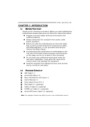
... a dry and stable working environment with sufficient lighting. „ Always disconnect the computer from power outlet before operation. „ Before you for ATX Case X 1 User's Manual X 1 Fully Setup Driver CD X 1 FDD Cable X 1 (optional) USB 2.0 Cable X1 (optional) S/PDIF out Cable X 1 (optional) Serial ATA Power Cable X 2 (optional) Note: The package contents may...
... a dry and stable working environment with sufficient lighting. „ Always disconnect the computer from power outlet before operation. „ Before you for ATX Case X 1 User's Manual X 1 Fully Setup Driver CD X 1 FDD Cable X 1 (optional) USB 2.0 Cable X1 (optional) S/PDIF out Cable X 1 (optional) Serial ATA Power Cable X 2 (optional) Note: The package contents may...
Setup Manual
Page 6
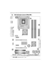
SATA2 RS TSW1 PWRSW1 4 Motherboard Manual 1.5 MOTHERBOARD LAYOUT (TP45 HP) JKBMS1 JATXPWR1 JUSB2 LGA775 CPU1 JCFAN1 DDR 2_A 1 DDR 2_A 2 DDR 2_B 1 DDR 2_B 2 BIOS JUSBV1 JUSB1 JRJ45USB1 JNFAN1 JAUDIO1 J1 Int el P45 JATXPWR2 LAN JCDIN1 PEX1_2 PEX16_1 JPE1 JPE3 JPE5 JPE7 PEX1_1 JPE2 JPE4 JPE6 JPE8 JPE9 BAT1 I ntel ICH10 JCMO S1 IDE1 CODEC PEX16_2 PCI1 SATA5 IDE SATA3 SATA1 JSPDIF_OUT1 PCI2 JAUDIOF1 JCOM1 JPRNT1 FDD1 Super I/O SATA6 SATA4 JUSBV2 JSFAN1 JUSB5 JUSB4 JUSB3 JPANEL1 LED_D2 LED_D1 Note: ■ represents the 1st pin.
SATA2 RS TSW1 PWRSW1 4 Motherboard Manual 1.5 MOTHERBOARD LAYOUT (TP45 HP) JKBMS1 JATXPWR1 JUSB2 LGA775 CPU1 JCFAN1 DDR 2_A 1 DDR 2_A 2 DDR 2_B 1 DDR 2_B 2 BIOS JUSBV1 JUSB1 JRJ45USB1 JNFAN1 JAUDIO1 J1 Int el P45 JATXPWR2 LAN JCDIN1 PEX1_2 PEX16_1 JPE1 JPE3 JPE5 JPE7 PEX1_1 JPE2 JPE4 JPE6 JPE8 JPE9 BAT1 I ntel ICH10 JCMO S1 IDE1 CODEC PEX16_2 PCI1 SATA5 IDE SATA3 SATA1 JSPDIF_OUT1 PCI2 JAUDIOF1 JCOM1 JPRNT1 FDD1 Super I/O SATA6 SATA4 JUSBV2 JSFAN1 JUSB5 JUSB4 JUSB3 JPANEL1 LED_D2 LED_D1 Note: ■ represents the 1st pin.
Setup Manual
Page 8
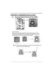
When the CPU is removed, cover the Pin Cap on the empty socket to a 90-degree angle. 6 Motherboard Manual CHAPTER 2: HARDWARE INSTALLATION 2.1 INSTALLING CENTRAL PROCESSING UNIT (CPU) Special Notice: Remove Pin Cap before installation, and make good preservation for future use. Pin Cap Step 1: Pull the socket locking lever out from the socket and then raise the lever up to ensure pin legs won't be damaged.
When the CPU is removed, cover the Pin Cap on the empty socket to a 90-degree angle. 6 Motherboard Manual CHAPTER 2: HARDWARE INSTALLATION 2.1 INSTALLING CENTRAL PROCESSING UNIT (CPU) Special Notice: Remove Pin Cap before installation, and make good preservation for future use. Pin Cap Step 1: Pull the socket locking lever out from the socket and then raise the lever up to ensure pin legs won't be damaged.

Setup Manual
Page 10
Motherboard Manual 2.2 FAN HEADERS These fan headers support cooling-fans built in the computer. Connect the fan cable to the connector while matching the black wire to ...
Motherboard Manual 2.2 FAN HEADERS These fan headers support cooling-fans built in the computer. Connect the fan cable to the connector while matching the black wire to ...
Setup Manual
Page 12
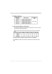
.../512MB/1GB/2GB DDR2_A2 256MB/512MB/1GB/2GB DDR2_B1 256MB/512MB/1GB/2GB DDR2_B2 256MB/512MB/1GB/2GB Total Memory Size Max is 8GB. Motherboard Manual B.
.../512MB/1GB/2GB DDR2_A2 256MB/512MB/1GB/2GB DDR2_B1 256MB/512MB/1GB/2GB DDR2_B2 256MB/512MB/1GB/2GB Total Memory Size Max is 8GB. Motherboard Manual B.
Setup Manual
Page 14
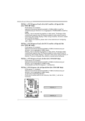
Motherboard Manual PEX16_1: PCI-Express Gen2 x16 (x16/CrossFire x8 Speed) Slot (For TP45 HP Only) - PEX16_1 slot is reserved for graphics or video cards. The design ...
Motherboard Manual PEX16_1: PCI-Express Gen2 x16 (x16/CrossFire x8 Speed) Slot (For TP45 HP Only) - PEX16_1 slot is reserved for graphics or video cards. The design ...

Setup Manual
Page 16
... closed Pin1-2 closed 3.2 DETAIL SETTINGS JPANEL1: Front Panel Header This 16-pin connector includes Power-on, Reset, HDD LED, Power LED, and speaker connection. Motherboard Manual CHAPTER 3: HEADERS & JUMPERS SETUP 3.1 HOW TO SETUP JUMPERS The illustration shows how to connect the PC case's front panel switch functions.
... closed Pin1-2 closed 3.2 DETAIL SETTINGS JPANEL1: Front Panel Header This 16-pin connector includes Power-on, Reset, HDD LED, Power LED, and speaker connection. Motherboard Manual CHAPTER 3: HEADERS & JUMPERS SETUP 3.1 HOW TO SETUP JUMPERS The illustration shows how to connect the PC case's front panel switch functions.
Setup Manual
Page 18
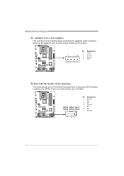
Pin Assignment 1 +12V 1 4 2 Ground 3 Ground 4 VCC SATA1~SATA6: Serial ATA Connectors The motherboard has a PCI to SATA Controller with 6 channels SATA interface, it satisfies the SATA 2.0 spec and with transfer rate of 3.0Gb/s. SATA5 SATA3 SATA1 SATA6 SATA4 SATA2 Pin Assignment 1 Ground 2 TX+ 3 TX4 Ground 5 RX6 RX+ 7 Ground 741 16 Motherboard Manual J1: Auxiliary Power for Graphics This connector is an auxiliary power connection for the graphics card provides better graphics performance. Exclusive power for graphics cards.
Pin Assignment 1 +12V 1 4 2 Ground 3 Ground 4 VCC SATA1~SATA6: Serial ATA Connectors The motherboard has a PCI to SATA Controller with 6 channels SATA interface, it satisfies the SATA 2.0 spec and with transfer rate of 3.0Gb/s. SATA5 SATA3 SATA1 SATA6 SATA4 SATA2 Pin Assignment 1 Ground 2 TX+ 3 TX4 Ground 5 RX6 RX+ 7 Ground 741 16 Motherboard Manual J1: Auxiliary Power for Graphics This connector is an auxiliary power connection for the graphics card provides better graphics performance. Exclusive power for graphics cards.
Setup Manual
Page 20
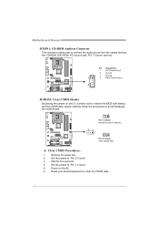
... CMOS data, please carefully follow the procedures to "Pin 2-3 close ". 5. Reset your desired password or clear the CMOS data. 18 Wait for five seconds. 4. Motherboard Manual JCDIN1: CD-ROM Audio-in Connector This connector allows user to "Pin 1-2 close ". 3.
... CMOS data, please carefully follow the procedures to "Pin 2-3 close ". 5. Reset your desired password or clear the CMOS data. 18 Wait for five seconds. 4. Motherboard Manual JCDIN1: CD-ROM Audio-in Connector This connector allows user to "Pin 1-2 close ". 3.
Setup Manual
Page 22
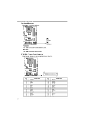
... PWRSW1 PWRSW1: This is an on -board Power Switch button. JPRNT1: Printer Port Connector This header allows you to connect printer on -board buttons. Motherboard Manual On-Board Buttons There are 2 on the PC. 25 1 Pin Assignment 1 -Strobe 2 -ALF 3 Data 0 4 -Error 5 Data 1 6 -Init 7 Data 2 8 -Scltin 9 Data 3 10 Ground 11 Data 4 12...
... PWRSW1 PWRSW1: This is an on -board Power Switch button. JPRNT1: Printer Port Connector This header allows you to connect printer on -board buttons. Motherboard Manual On-Board Buttons There are 2 on the PC. 25 1 Pin Assignment 1 -Strobe 2 -ALF 3 Data 0 4 -Error 5 Data 1 6 -Init 7 Data 2 8 -Scltin 9 Data 3 10 Ground 11 Data 4 12...
Setup Manual
Page 24
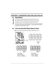
Motherboard Manual CHAPTER 4: CROSSFIRE FUNCTION (FOR TP45 HP) 4.1 REQUIREMENTS Only Windows XP/Vista supports CrossFire (Dual Video) function. The power supply unit must provide at least the ...
Motherboard Manual CHAPTER 4: CROSSFIRE FUNCTION (FOR TP45 HP) 4.1 REQUIREMENTS Only Windows XP/Vista supports CrossFire (Dual Video) function. The power supply unit must provide at least the ...

Setup Manual
Page 26
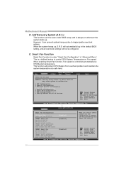
... Elite and Casual overclockers. Over-Clocking Navigator [Normal] =========== Automate OverClock System =========== Auto OverClock System [V6-Tech Engine] Manual OverClock System Intel(R) SpeedStep(tm) tech [Enabled] Ratio CMOS Setting [ x10.0] CPU Frequency Setting [266] Over Clock ... may be different from USB Flash Drive or FDD Self Recovery System (S.R.S) Smart Fan Function CMOS Reloading Program !! Motherboard Manual CHAPTER 5: T-SERIES BIOS & SOFTWARE 5.1 T-SERIES BIOS T-Series BIOS Features Overclocking Navigator Engine (O.N.E.) Memory Integration Test (M.I.T.,...
... Elite and Casual overclockers. Over-Clocking Navigator [Normal] =========== Automate OverClock System =========== Auto OverClock System [V6-Tech Engine] Manual OverClock System Intel(R) SpeedStep(tm) tech [Enabled] Ratio CMOS Setting [ x10.0] CPU Frequency Setting [266] Over Clock ... may be different from USB Flash Drive or FDD Self Recovery System (S.R.S) Smart Fan Function CMOS Reloading Program !! Motherboard Manual CHAPTER 5: T-SERIES BIOS & SOFTWARE 5.1 T-SERIES BIOS T-Series BIOS Features Overclocking Navigator Engine (O.N.E.) Memory Integration Test (M.I.T.,...

Setup Manual
Page 27
...[Auto] > DRAM Timing Configuration > Clock Gen Configuration > Voltage Configuration Memory Test [Disabled] Options Normal Automate OverClock Manual OverClock Select Screen Select Item EnterGo to be dynamically changed by software. Intel(R) SpeedStep(tm) Tech This item allows... you to malfunction. Over-Clocking Navigator [Normal] =========== Automate OverClock System =========== Auto OverClock System [V6-Tech Engine] Manual OverClock System Intel(R) SpeedStep(tm) tech [EnOapbtlieonds] Ratio CMOS Setting Nor[maxl10.0] CPU Frequency Setting Aut[o2m6a6t]e OverClock...
...[Auto] > DRAM Timing Configuration > Clock Gen Configuration > Voltage Configuration Memory Test [Disabled] Options Normal Automate OverClock Manual OverClock Select Screen Select Item EnterGo to be dynamically changed by software. Intel(R) SpeedStep(tm) Tech This item allows... you to malfunction. Over-Clocking Navigator [Normal] =========== Automate OverClock System =========== Auto OverClock System [V6-Tech Engine] Manual OverClock System Intel(R) SpeedStep(tm) tech [EnOapbtlieonds] Ratio CMOS Setting Nor[maxl10.0] CPU Frequency Setting Aut[o2m6a6t]e OverClock...

Setup Manual
Page 28
...DRAM timing settings. Over-Clocking Navigator [Normal] =========== Automate OverClock System =========== Auto OverClock System [V6-Tech Engine] Manual OverClock System Intel(R) SpeedStep(tm) tech [EnOapbtlieonds] Ratio CMOS Setting Nor[maxl10.0] CPU Frequency Setting Aut[o2m6a6t]e ...[Auto] > DRAM Timing Configuration > Clock Gen Configuration > Voltage Configuration Memory Test [Disabled] Options Normal Automate OverClock Manual OverClock Select Screen Select Item EnterGo to increase the system performance, named A.O.S. DRAM Timing Configuration Enter this item for ...
...DRAM timing settings. Over-Clocking Navigator [Normal] =========== Automate OverClock System =========== Auto OverClock System [V6-Tech Engine] Manual OverClock System Intel(R) SpeedStep(tm) tech [EnOapbtlieonds] Ratio CMOS Setting Nor[maxl10.0] CPU Frequency Setting Aut[o2m6a6t]e ...[Auto] > DRAM Timing Configuration > Clock Gen Configuration > Voltage Configuration Memory Test [Disabled] Options Normal Automate OverClock Manual OverClock Select Screen Select Item EnterGo to increase the system performance, named A.O.S. DRAM Timing Configuration Enter this item for ...

Setup Manual
Page 29
...over-clock performance. Over-Clocking Navigator [Automate OverClock] =========== Automate OverClock System =========== Auto OverClock System [V8-Tech Engine] Manual OverClock System Intel(R) SpeedStep(tm) tech [Enabled] Ratio CMOS Setting [ x10.0] CPU Frequency Setting [266] Over Clock..., Inc. 27 Over-Clocking Navigator [Automate OverClock] =========== Automate OverClock System =========== Auto OverClock System [V12-Tech Engine] Manual OverClock System Intel(R) SpeedStep(tm) tech [Enabled] Ratio CMOS Setting [ x10.0] CPU Frequency Setting [266] Over Clock...
...over-clock performance. Over-Clocking Navigator [Automate OverClock] =========== Automate OverClock System =========== Auto OverClock System [V8-Tech Engine] Manual OverClock System Intel(R) SpeedStep(tm) tech [Enabled] Ratio CMOS Setting [ x10.0] CPU Frequency Setting [266] Over Clock..., Inc. 27 Over-Clocking Navigator [Automate OverClock] =========== Automate OverClock System =========== Auto OverClock System [V12-Tech Engine] Manual OverClock System Intel(R) SpeedStep(tm) tech [Enabled] Ratio CMOS Setting [ x10.0] CPU Frequency Setting [266] Over Clock...

Setup Manual
Page 30
... cause system to malfunction. Over-Clocking Navigator [Normal] =========== Automate OverClock System =========== Auto OverClock System [V6-Tech Engine] Manual OverClock System Intel(R) SpeedStep(tm) tech [Enabled] Ratio CMOS Setting [ x10.0] CPU Frequency Setting [266] Over Clock ...malfunction. Run this test. Over-Clocking Navigator [Normal] =========== Automate OverClock System =========== Auto OverClock System [V6-Tech Engine] Manual OverClock System Intel(R) SpeedStep(tm) tech [Enabled] Ratio CMOS Setting [ x10.0] CPU Frequency Setting [266] Over Clock...
... cause system to malfunction. Over-Clocking Navigator [Normal] =========== Automate OverClock System =========== Auto OverClock System [V6-Tech Engine] Manual OverClock System Intel(R) SpeedStep(tm) tech [Enabled] Ratio CMOS Setting [ x10.0] CPU Frequency Setting [266] Over Clock ...malfunction. Run this test. Over-Clocking Navigator [Normal] =========== Automate OverClock System =========== Auto OverClock System [V6-Tech Engine] Manual OverClock System Intel(R) SpeedStep(tm) tech [Enabled] Ratio CMOS Setting [ x10.0] CPU Frequency Setting [266] Over Clock...
Setup Manual
Page 32
... 1985-200x, American Megatrends, Inc. 30 Smart Fan Function Smart Fan Function is a brilliant feature to inappropriate overclock actions. This is under BIOS setup; Motherboard Manual D. When the system hangs up . When enabling Smart Fan function, Fan speed is always on whenever the system starts up , S.R.S. Fan speed. Self Recovery System...
... 1985-200x, American Megatrends, Inc. 30 Smart Fan Function Smart Fan Function is a brilliant feature to inappropriate overclock actions. This is under BIOS setup; Motherboard Manual D. When the system hangs up . When enabling Smart Fan function, Fan speed is always on whenever the system starts up , S.R.S. Fan speed. Self Recovery System...

Setup Manual
Page 34
... Auto-run function has been enabled. 2. Launching T-Series Software After the installation process, you will help you easily do over-clocking under windows environment. Motherboard Manual 5.2 T-SERIES SOFTWARE Installing T-Series Software 1. In this panel you will be launched; OverClock 3 OverClock 3 is Main Panel.
... Auto-run function has been enabled. 2. Launching T-Series Software After the installation process, you will help you easily do over-clocking under windows environment. Motherboard Manual 5.2 T-SERIES SOFTWARE Installing T-Series Software 1. In this panel you will be launched; OverClock 3 OverClock 3 is Main Panel.

Setup Manual
Page 35
A warning dialog as below will set the best and stable performance and frequency automatically. Over Clock Panel Restore Default Settings AUTO Over-Clock V3/V6/V9 Engine Real-time Ove r-clock TP45 HP/TP43 HP Manual Adjust CPU Clock Test & Apply Manual Setting s AUTO User can click this button and the utility will show up to notify you that the system may become unstable, click on "OK" to continue. 33
A warning dialog as below will set the best and stable performance and frequency automatically. Over Clock Panel Restore Default Settings AUTO Over-Clock V3/V6/V9 Engine Real-time Ove r-clock TP45 HP/TP43 HP Manual Adjust CPU Clock Test & Apply Manual Setting s AUTO User can click this button and the utility will show up to notify you that the system may become unstable, click on "OK" to continue. 33

