

TForce4 AM2 user's manual
Page 1
... to Part 15 of merchantability or fitness for any party beforehand. The content of their respective companies. These limits are trademarks of this user's manual is subject to provide reasonable protection against harmful interference in a residential installation. There is not allowed without notice and we will not occur in... for any purpose. The vendor makes no guarantee that interference will not be changed without first obtaining the vendor's approval in writing. TForce4 AM2 Setup Manual FCC Information and Copyright This equipment has been tested and found in this user...
... to Part 15 of merchantability or fitness for any party beforehand. The content of their respective companies. These limits are trademarks of this user's manual is subject to provide reasonable protection against harmful interference in a residential installation. There is not allowed without notice and we will not occur in... for any purpose. The vendor makes no guarantee that interference will not be changed without first obtaining the vendor's approval in writing. TForce4 AM2 Setup Manual FCC Information and Copyright This equipment has been tested and found in this user...

TForce4 AM2 user's manual
Page 3
... and water. 1.2 PACKAGE CHECKLIST FDD Cable X 1 HDD Cable X 1 Serial ATA Cable X 1 Serial ATA Power Cable X 1 Rear I/O Panel for choosing our product. TForce4 AM2 CHAPTER 1: INTRODUCTION 1.1 BEFORE YOU START Thank you take the motherboard out from anti-static bag, ground yourself properly by touching any safely grounded appliance, or...working environment with sufficient lighting. „ Always disconnect the computer from power outlet before operation. „ Before you for ATX Case X 1 User's Manual X 1 Fully Setup Driver CD X 1 USB 2.0 Cable X1 (optional) S/PDIF out Cable X 1 (optional) 1
... and water. 1.2 PACKAGE CHECKLIST FDD Cable X 1 HDD Cable X 1 Serial ATA Cable X 1 Serial ATA Power Cable X 1 Rear I/O Panel for choosing our product. TForce4 AM2 CHAPTER 1: INTRODUCTION 1.1 BEFORE YOU START Thank you take the motherboard out from anti-static bag, ground yourself properly by touching any safely grounded appliance, or...working environment with sufficient lighting. „ Always disconnect the computer from power outlet before operation. „ Before you for ATX Case X 1 User's Manual X 1 Fully Setup Driver CD X 1 USB 2.0 Cable X1 (optional) S/PDIF out Cable X 1 (optional) 1

TForce4 AM2 user's manual
Page 4
... (with Smart Fan function) x3 System Fan Power supply x1 For chassis intruder detection function x1 Restore CMOS data to factory default Motherboard Manual 1.3 MOTHERBOARD FEATURES SPEC Socket AM2 AMD 64 Architecture enables 32 and 64 bit computing CPU AMD Athlon 64 / Athlon 64 FX / Althlon Supports Hyper Transport and Cool=n=Quiet...
... (with Smart Fan function) x3 System Fan Power supply x1 For chassis intruder detection function x1 Restore CMOS data to factory default Motherboard Manual 1.3 MOTHERBOARD FEATURES SPEC Socket AM2 AMD 64 Architecture enables 32 and 64 bit computing CPU AMD Athlon 64 / Athlon 64 FX / Althlon Supports Hyper Transport and Cool=n=Quiet...

TForce4 AM2 user's manual
Page 6
Motherboard Manual 1.5 MOTHERBOARD LAYOUT JKBMS1 JKBMSV1 JATXPWR2 JCFAN1 JCOM1 JPRNT1 DDR2A1 DDR2B1 DDR2A2 DDR2B2 JCOM2 (optional) JUSB4 JUSBV1 JATXPWR1 JUSBLAN1 LAN JAUDIO1 JAUDIO1 PCI-EX16 Codec JCDIN1 PCI-EX1_1 PCI-EX1_2 nVIDIA nForce4 JDDRII_2.3V JNFAN1 IDE1 IDE2 Super I/O BIOS LED_D1 LED_D2 PCI1 PCI2 JSPDIF_OUT1 PCI3 PCI4 JUSB2 JUSB3 JUSB4 BAT1 JSATA1 JSATA2 JSATA3 JSATA4 JUSBV2 JCMOS1 FDD1 RSTSW2 PWRSW1 JPANEL1 JSFAN2 JSFAN1 Note: ■ represents the 1st pin. 4
Motherboard Manual 1.5 MOTHERBOARD LAYOUT JKBMS1 JKBMSV1 JATXPWR2 JCFAN1 JCOM1 JPRNT1 DDR2A1 DDR2B1 DDR2A2 DDR2B2 JCOM2 (optional) JUSB4 JUSBV1 JATXPWR1 JUSBLAN1 LAN JAUDIO1 JAUDIO1 PCI-EX16 Codec JCDIN1 PCI-EX1_1 PCI-EX1_2 nVIDIA nForce4 JDDRII_2.3V JNFAN1 IDE1 IDE2 Super I/O BIOS LED_D1 LED_D2 PCI1 PCI2 JSPDIF_OUT1 PCI3 PCI4 JUSB2 JUSB3 JUSB4 BAT1 JSATA1 JSATA2 JSATA3 JSATA4 JUSBV2 JCMOS1 FDD1 RSTSW2 PWRSW1 JPANEL1 JSFAN2 JSFAN1 Note: ■ represents the 1st pin. 4

TForce4 AM2 user's manual
Page 8
Connect the CPU FAN power cable to complete the installation. This completes the installation. 6 Step 5: Put the CPU Fan on the CPU and buckle it. Motherboard Manual Step 4: Hold the CPU down firmly, and then close the lever toward direct B to the JCFAN1.
Connect the CPU FAN power cable to complete the installation. This completes the installation. 6 Step 5: Put the CPU Fan on the CPU and buckle it. Motherboard Manual Step 4: Hold the CPU down firmly, and then close the lever toward direct B to the JCFAN1.

TForce4 AM2 user's manual
Page 10
Insert the DIMM vertically and firmly into the slot until the retaining chip snap back in place and the DIMM is properly seated. 8 Align a DIMM on the slot such that the notch on the DIMM matches the break on the Slot. 2. Unlock a DIMM slot by pressing the retaining clips outward. Memory Modules 1. DDR2A1 DDR2B1 DDR2A2 DDR2B2 Motherboard Manual 2.3 INSTALLING SYSTEM MEMORY A.
Insert the DIMM vertically and firmly into the slot until the retaining chip snap back in place and the DIMM is properly seated. 8 Align a DIMM on the slot such that the notch on the DIMM matches the break on the Slot. 2. Unlock a DIMM slot by pressing the retaining clips outward. Memory Modules 1. DDR2A1 DDR2B1 DDR2A2 DDR2B2 Motherboard Manual 2.3 INSTALLING SYSTEM MEMORY A.

TForce4 AM2 user's manual
Page 12
... you can connect up to IDE1. 40 39 2 IDE2 1 IDE1 10 The first hard drive should always be connected to four hard disk drives. Motherboard Manual CONNECTORS AND SLOTS FDD1: Floppy Disk Connector The motherboard provides a standard floppy disk connector that provides PIO Mode 0~4, Bus Master, and Ultra DMA 33/66...
... you can connect up to IDE1. 40 39 2 IDE2 1 IDE1 10 The first hard drive should always be connected to four hard disk drives. Motherboard Manual CONNECTORS AND SLOTS FDD1: Floppy Disk Connector The motherboard provides a standard floppy disk connector that provides PIO Mode 0~4, Bus Master, and Ultra DMA 33/66...

TForce4 AM2 user's manual
Page 14
... (-) Reset button 15 Power button 16 Ground Function Sleep button N/A Power LED Power-on , Reset, HDD LED, Power LED, Sleep button and speaker connection. Motherboard Manual CHAPTER 3: HEADERS & JUMPERS SETUP 3.1 HOW TO SETUP JUMPERS The illustration shows how to connect the PC case's front panel switch functions. When the jumper cap...
... (-) Reset button 15 Power button 16 Ground Function Sleep button N/A Power LED Power-on , Reset, HDD LED, Power LED, Sleep button and speaker connection. Motherboard Manual CHAPTER 3: HEADERS & JUMPERS SETUP 3.1 HOW TO SETUP JUMPERS The illustration shows how to connect the PC case's front panel switch functions. When the jumper cap...

TForce4 AM2 user's manual
Page 16
Motherboard Manual JKBMSV1: Power Source Selection Headers for Keyboard/Mouse Pin 1-2 Close: JKBMSV1: +5V for PS/2 keyboard and mouse。 Pin 2-3 Close: JKBMSV1: PS/2 keyboard and mouse ...
Motherboard Manual JKBMSV1: Power Source Selection Headers for Keyboard/Mouse Pin 1-2 Close: JKBMSV1: +5V for PS/2 keyboard and mouse。 Pin 2-3 Close: JKBMSV1: PS/2 keyboard and mouse ...

TForce4 AM2 user's manual
Page 18
...: 1. Remove AC power line. 2. Reset your desired password or clear the CMOS data. 16 Wait for five seconds. 4. Set the jumper to "Pin 1-2 close ". 3. Motherboard Manual JCDIN1: CD-ROM Audio-in Connector This connector allows user to connect the audio source from the variaty devices, like CD-ROM, DVD-ROM, PCI...
...: 1. Remove AC power line. 2. Reset your desired password or clear the CMOS data. 16 Wait for five seconds. 4. Set the jumper to "Pin 1-2 close ". 3. Motherboard Manual JCDIN1: CD-ROM Audio-in Connector This connector allows user to connect the audio source from the variaty devices, like CD-ROM, DVD-ROM, PCI...

TForce4 AM2 user's manual
Page 20
The Default setting is placed on Pin 2-3, memory voltage can 't be manually adjusted under COMS setup. Note: 1. Please refer to pin1-2 Closed. Motherboard Manual Header for Memory Voltage Overclocking: JDDRII_2.3V When processing Memory Voltage Overclocking, please place the jumper to the table below for different messages: LED_D1 ON ...
The Default setting is placed on Pin 2-3, memory voltage can 't be manually adjusted under COMS setup. Note: 1. Please refer to pin1-2 Closed. Motherboard Manual Header for Memory Voltage Overclocking: JDDRII_2.3V When processing Memory Voltage Overclocking, please place the jumper to the table below for different messages: LED_D1 ON ...

TForce4 AM2 user's manual
Page 22
.... Depending on the system environment. RAID 1: RAID 1 defines techniques for mirroring data. It breaks up to 6 or 8. Block 1 Block 3 Block 5 Block 2 Block 4 Block 6 20 Motherboard Manual CHAPTER 4: NVIDIA RAID FUNCTIONS 4.1 OPERATION SYSTEM z Supports Windows XP Home/Professional Edition, and Windows 2000 Professional. 4.2 RAID ARRAYS NVRAID supports the following types of the...
.... Depending on the system environment. RAID 1: RAID 1 defines techniques for mirroring data. It breaks up to 6 or 8. Block 1 Block 3 Block 5 Block 2 Block 4 Block 6 20 Motherboard Manual CHAPTER 4: NVIDIA RAID FUNCTIONS 4.1 OPERATION SYSTEM z Supports Windows XP Home/Professional Edition, and Windows 2000 Professional. 4.2 RAID ARRAYS NVRAID supports the following types of the...

TForce4 AM2 user's manual
Page 23
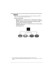
... that eliminates tedious manual backups to more expensive and less reliable media. Performance is ideal for small databases or any other drive. Drawbacks: Requires 2 drives for high-availability solutions, or as a form of automatic backup that requires fault tolerance and minimal capacity. Benefits: Provides 100% data redundancy. TForce4 AM2 RAID 1: Every...
... that eliminates tedious manual backups to more expensive and less reliable media. Performance is ideal for small databases or any other drive. Drawbacks: Requires 2 drives for high-availability solutions, or as a form of automatic backup that requires fault tolerance and minimal capacity. Benefits: Provides 100% data redundancy. TForce4 AM2 RAID 1: Every...
TForce4 AM2 user's manual
Page 24
... information, please refer to the Driver CD, or go to http://www.nvidia.com/page/pg_20011106217193.html to download NVIDIA nForce Tutorial Flash. 22 Motherboard Manual RAID 0+1: RAID 0 drives can be simultaneously used with other RAID levels in a RAID 0+1 solution for data redundancy, the same as RAID level 1. - May be mirrored...
... information, please refer to the Driver CD, or go to http://www.nvidia.com/page/pg_20011106217193.html to download NVIDIA nForce Tutorial Flash. 22 Motherboard Manual RAID 0+1: RAID 0 drives can be simultaneously used with other RAID levels in a RAID 0+1 solution for data redundancy, the same as RAID level 1. - May be mirrored...

TForce4 AM2 user's manual
Page 26
Manual Overclock System (M.O.S.) MOS is designed for both Elite and Casual overclockers. It allows users to customize personal overclock settings. 24 Motherboard Manual 5.2: T-POWER BIOS FEATURE A. Overclocking Navigator Engine (O.N.E.): ONE provides two powerful overclocking engines: MOS and AOS for experienced overclock users.
Manual Overclock System (M.O.S.) MOS is designed for both Elite and Casual overclockers. It allows users to customize personal overclock settings. 24 Motherboard Manual 5.2: T-POWER BIOS FEATURE A. Overclocking Navigator Engine (O.N.E.): ONE provides two powerful overclocking engines: MOS and AOS for experienced overclock users.

TForce4 AM2 user's manual
Page 28
... in overclock field, BET had developed an easy, fast, and powerful feature to increase the system performance, named A.O.S. Based on many tests and experiments, A.O.S. Motherboard Manual Automatic Overclock System (A.O.S.) For beginners in a single step.
... in overclock field, BET had developed an easy, fast, and powerful feature to increase the system performance, named A.O.S. Based on many tests and experiments, A.O.S. Motherboard Manual Automatic Overclock System (A.O.S.) For beginners in a single step.

TForce4 AM2 user's manual
Page 30
... from "Enable" to "Disable" to test memory compatibilities, and no extra devices or software are needed. MIT allows users to complete the test. 28 Motherboard Manual C. Step 3: When the process is done, change the setting back from CMOS setup and reboot the system to ensure the memory stability.
... from "Enable" to "Disable" to test memory compatibilities, and no extra devices or software are needed. MIT allows users to complete the test. 28 Motherboard Manual C. Step 3: When the process is done, change the setting back from CMOS setup and reboot the system to ensure the memory stability.

TForce4 AM2 user's manual
Page 32
... fan starts to this set value, the CPU fan will turn off. Choices: 32℃ (default). The range is under Full Speed. Fan speed. Motherboard Manual F. Smart Fan Function: Smart Fan Function is from 0℃~127℃, with an interval of 1℃. The range is from 0℃~127℃, with an...
... fan starts to this set value, the CPU fan will turn off. Choices: 32℃ (default). The range is under Full Speed. Fan speed. Motherboard Manual F. Smart Fan Function: Smart Fan Function is from 0℃~127℃, with an interval of 1℃. The range is from 0℃~127℃, with an...

TForce4 AM2 user's manual
Page 34
Motherboard Manual 5.3 T-POWER WINDOWS FEATURE A.Hardware Monitor: T-Power Hardware monitor allows users to pop-up warning dialogue-box when PC system is abnormal. Hardware Monitor Toolbar i. Dialogue-...
Motherboard Manual 5.3 T-POWER WINDOWS FEATURE A.Hardware Monitor: T-Power Hardware monitor allows users to pop-up warning dialogue-box when PC system is abnormal. Hardware Monitor Toolbar i. Dialogue-...

TForce4 AM2 user's manual
Page 36
... voltage. ii. Reference data This column represents the status of battery voltage. VCore This item displays the CPU voltage, represented by a light green line. Motherboard Manual CPU/Battery Voltage i. VBAT This item displays the CMOS battery voltage, represented by a light blue line. Users can set the upper and lower limit by...
... voltage. ii. Reference data This column represents the status of battery voltage. VCore This item displays the CPU voltage, represented by a light green line. Motherboard Manual CPU/Battery Voltage i. VBAT This item displays the CMOS battery voltage, represented by a light blue line. Users can set the upper and lower limit by...

