

MANUAL
Page 2
Table of Contents Chapter 1: Introduction 3 1.1 Before You Start 3 1.2 Package Checklist 3 1.3 Motherboard Features 4 1.4 Rear Panel Connectors (for TF7050-M2 6 1.5 Rear Panel Connectors (for TF7025-M2 7 1.6 Motherboard Layout (for TF7050-M2 8 1.7 Motherboard Layout (for TF7025-M2 9 Chapter 2: Hardware Installation 10 2.1 Installing Central Processing Unit (CPU 10 2.2 FAN Headers 12 2.3 Installing System Memory 13 2.4 Connectors and Slots 15 Chapter 3: Headers & Jumpers Setup ...
Table of Contents Chapter 1: Introduction 3 1.1 Before You Start 3 1.2 Package Checklist 3 1.3 Motherboard Features 4 1.4 Rear Panel Connectors (for TF7050-M2 6 1.5 Rear Panel Connectors (for TF7025-M2 7 1.6 Motherboard Layout (for TF7050-M2 8 1.7 Motherboard Layout (for TF7025-M2 9 Chapter 2: Hardware Installation 10 2.1 Installing Central Processing Unit (CPU 10 2.2 FAN Headers 12 2.3 Installing System Memory 13 2.4 Connectors and Slots 15 Chapter 3: Headers & Jumpers Setup ...
MANUAL
Page 3
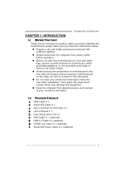
... PACKAGE CHECKLIST HDD Cable X 1 Serial ATA Cable X 1 Rear I/O Panel for choosing our product. Before you start installing the motherboard, please make sure you follow the instructions below: „ Prepare a dry and stable working environment with sufficient lighting. „...USB 2.0 Cable X1 (optional) S/PDIF out Cable X 1 (optional) Serial ATA Power Cable X 1 (optional) 3 TF7050-M2/TF7025-M2 CHAPTER 1: INTRODUCTION 1.1 BEFORE YOU START Thank you take the motherboard out from anti-static bag, ground yourself properly by touching any safely grounded appliance, or use grounded wrist strap to...
... PACKAGE CHECKLIST HDD Cable X 1 Serial ATA Cable X 1 Rear I/O Panel for choosing our product. Before you start installing the motherboard, please make sure you follow the instructions below: „ Prepare a dry and stable working environment with sufficient lighting. „...USB 2.0 Cable X1 (optional) S/PDIF out Cable X 1 (optional) Serial ATA Power Cable X 1 (optional) 3 TF7050-M2/TF7025-M2 CHAPTER 1: INTRODUCTION 1.1 BEFORE YOU START Thank you take the motherboard out from anti-static bag, ground yourself properly by touching any safely grounded appliance, or use grounded wrist strap to...
MANUAL
Page 4
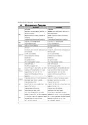
... Master Mode supports PIO Mode 0~4, supports PIO Mode 0~4, Integrated Serial ATA Controller Integrated Serial ATA Controller SATA II Data transfer rates up to 3 Gb/s. Motherboard Manual 1.3 MOTHERBOARD FEATURES TF7050-M2 TF7025-M2 Socket AM2 Socket AM2 AMD Athlon 64 / Athlon 64 FX / Athlon 64 x2 / AMD Athlon 64 / Athlon 64 FX / Athlon 64 x2 / Sempron...
... Master Mode supports PIO Mode 0~4, supports PIO Mode 0~4, Integrated Serial ATA Controller Integrated Serial ATA Controller SATA II Data transfer rates up to 3 Gb/s. Motherboard Manual 1.3 MOTHERBOARD FEATURES TF7050-M2 TF7025-M2 Socket AM2 Socket AM2 AMD Athlon 64 / Athlon 64 FX / Athlon 64 x2 / AMD Athlon 64 / Athlon 64 FX / Athlon 64 x2 / Sempron...
MANUAL
Page 6
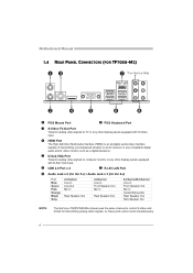
Motherboard Manual 1.4 REAR PANEL CONNECTORS (FOR TF7050-M2) X PS/2 Mouse Port Y PS/2 Keyboard Port Z S-Video TV-Out Port Transmit analog video signals to TV or any other display panels equipped with S-Video input. [ ...
Motherboard Manual 1.4 REAR PANEL CONNECTORS (FOR TF7050-M2) X PS/2 Mouse Port Y PS/2 Keyboard Port Z S-Video TV-Out Port Transmit analog video signals to TV or any other display panels equipped with S-Video input. [ ...
MANUAL
Page 8
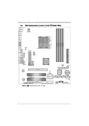
Motherboard Manual 1.6 MOTHERBOARD LAYOUT (FOR TF7050-M2) JKBMS1 JATXPWR2 JTVOUT1 JHDMI DIMMA1 DIMMB1 DIMMA2 DIMMB2 Socket A M2 VGA JUSB1 JUSBV1 JATXPWR1 IDE1 JUSBLAN1 JCFAN1 JAUDIO2 (for Ver 5.x) JAUDIO1 (for Ver 6.x) JAUDIOF1 JNFAN1 PEX1_1 GeForce 7050PV/ NF630a JUSBV2 JSFAN2 LED_D1 LED_D2 PEX16_1 LAN PCI1 JCOM1 Super I/O Codec JCDIN1 PCI2 JSPDIF_IN1 JSPDIF_OUT1 JPRNT1 FDD1 Note: ■ represents the 1st pin. JUSB2 JUSB3 JUSB4 BIOS BAT1 SATA1 SATA2 SATA3 SATA4 JCMOS1 JPANEL1 JSFAN1 PWRSW1 RSTSW1 8
Motherboard Manual 1.6 MOTHERBOARD LAYOUT (FOR TF7050-M2) JKBMS1 JATXPWR2 JTVOUT1 JHDMI DIMMA1 DIMMB1 DIMMA2 DIMMB2 Socket A M2 VGA JUSB1 JUSBV1 JATXPWR1 IDE1 JUSBLAN1 JCFAN1 JAUDIO2 (for Ver 5.x) JAUDIO1 (for Ver 6.x) JAUDIOF1 JNFAN1 PEX1_1 GeForce 7050PV/ NF630a JUSBV2 JSFAN2 LED_D1 LED_D2 PEX16_1 LAN PCI1 JCOM1 Super I/O Codec JCDIN1 PCI2 JSPDIF_IN1 JSPDIF_OUT1 JPRNT1 FDD1 Note: ■ represents the 1st pin. JUSB2 JUSB3 JUSB4 BIOS BAT1 SATA1 SATA2 SATA3 SATA4 JCMOS1 JPANEL1 JSFAN1 PWRSW1 RSTSW1 8

MANUAL
Page 9
TF7050-M2/TF7025-M2 1.7 MOTHERBOARD LAYOUT (FOR TF7025-M2) JKBMS1 JATXPWR2 VGA DIMMA1 DIMMB1 DIMMA2 DIMMB2 Socket A M2 DVI-D JUSB1 JUSBV1 JATXPWR1 IDE1 JUSBLAN1 JCFAN1 JAUDIO2 (for Ver 5.x) JAUDIO1 (for Ver 6.x) JAUDIOF1 JNFAN1 PEX1_1 GeForce 7025 / NF630a JUSBV2 JSFAN2 LED_D1 LED_D2 PEX16_1 LAN PCI1 JCOM1 Super I/O Codec JCDIN1 PCI2 JSPDIF_IN1 JSPDIF_OUT1 JPRNT1 FDD1 Note: ■ represents the 1st pin. JUSB2 JUSB3 JUSB4 BIOS BAT1 SATA1 SATA2 SATA3 SATA4 JCMOS1 JPANEL1 JSFAN1 PWRSW1 RSTSW1 9
TF7050-M2/TF7025-M2 1.7 MOTHERBOARD LAYOUT (FOR TF7025-M2) JKBMS1 JATXPWR2 VGA DIMMA1 DIMMB1 DIMMA2 DIMMB2 Socket A M2 DVI-D JUSB1 JUSBV1 JATXPWR1 IDE1 JUSBLAN1 JCFAN1 JAUDIO2 (for Ver 5.x) JAUDIO1 (for Ver 6.x) JAUDIOF1 JNFAN1 PEX1_1 GeForce 7025 / NF630a JUSBV2 JSFAN2 LED_D1 LED_D2 PEX16_1 LAN PCI1 JCOM1 Super I/O Codec JCDIN1 PCI2 JSPDIF_IN1 JSPDIF_OUT1 JPRNT1 FDD1 Note: ■ represents the 1st pin. JUSB2 JUSB3 JUSB4 BIOS BAT1 SATA1 SATA2 SATA3 SATA4 JCMOS1 JPANEL1 JSFAN1 PWRSW1 RSTSW1 9
MANUAL
Page 10
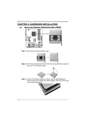
The CPU will fit only in the correct orientation. 10 Motherboard Manual CHAPTER 2: HARDWARE INSTALLATION 2.1 INSTALLING CENTRAL PROCESSING UNIT (CPU) Step 1: Remove the socket protection cap. Step 3: Look for the white triangle on socket, and the gold triangle on CPU should point towards this white triangle. Step 2: Pull the lever toward direction A from the socket and then raise the lever up to a 90-degree angle.
The CPU will fit only in the correct orientation. 10 Motherboard Manual CHAPTER 2: HARDWARE INSTALLATION 2.1 INSTALLING CENTRAL PROCESSING UNIT (CPU) Step 1: Remove the socket protection cap. Step 3: Look for the white triangle on socket, and the gold triangle on CPU should point towards this white triangle. Step 2: Pull the lever toward direction A from the socket and then raise the lever up to a 90-degree angle.

MANUAL
Page 12
... wire is the positive and should be connected to pin#2, and the black wire is Ground and should be different according to the fan manufacturer. Motherboard Manual 2.2 FAN HEADERS These fan headers support cooling-fans built in the computer. The fan cable and connector may be connected to pin#1.
... wire is the positive and should be connected to pin#2, and the black wire is Ground and should be different according to the fan manufacturer. Motherboard Manual 2.2 FAN HEADERS These fan headers support cooling-fans built in the computer. The fan cable and connector may be connected to pin#1.
MANUAL
Page 14
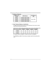
...of the same density in pairs, shown in the following table. Dual Channel Memory installation To trigger the Dual Channel function of the motherboard, the memory module must meet the following requirements: Install memory module of the memory module must be the same (x8 or x16) 14... Motherboard Manual B. C. Memory Capacity DIMM Socket Location DDR2 Module DIMMA1 256MB/512MB/1024MB DIMMB1 256MB/512MB/1024MB DIMMA2 256MB/512MB/1024MB DIMMB2 256MB/512MB...
...of the same density in pairs, shown in the following table. Dual Channel Memory installation To trigger the Dual Channel function of the motherboard, the memory module must meet the following requirements: Install memory module of the memory module must be the same (x8 or x16) 14... Motherboard Manual B. C. Memory Capacity DIMM Socket Location DDR2 Module DIMMA1 256MB/512MB/1024MB DIMMB1 256MB/512MB/1024MB DIMMA2 256MB/512MB/1024MB DIMMB2 256MB/512MB...

MANUAL
Page 15
This connector supports the provided floppy drive ribbon cables. 2 34 1 33 IDE1: Hard Disk Connector The motherboard has a 32-bit Enhanced PCI IDE Controller that supports 360K, 720K, 1.2M, 1.44M and 2.88M floppy disk types. The IDE connector can connect a master and a slave drive, so you can connect up to two hard disk drives. 40 39 21 15 TF7050-M2/TF7025-M2 2.4 CONNECTORS AND SLOTS FDD1: Floppy Disk Connector The motherboard provides a standard floppy disk connector that provides PIO Mode 0~4, Bus Master, and Ultra DMA 33/66/100/133 functionality.
This connector supports the provided floppy drive ribbon cables. 2 34 1 33 IDE1: Hard Disk Connector The motherboard has a 32-bit Enhanced PCI IDE Controller that supports 360K, 720K, 1.2M, 1.44M and 2.88M floppy disk types. The IDE connector can connect a master and a slave drive, so you can connect up to two hard disk drives. 40 39 21 15 TF7050-M2/TF7025-M2 2.4 CONNECTORS AND SLOTS FDD1: Floppy Disk Connector The motherboard provides a standard floppy disk connector that provides PIO Mode 0~4, Bus Master, and Ultra DMA 33/66/100/133 functionality.
MANUAL
Page 16
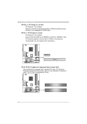
... up to 250MB/s per direction, for expansion cards. PCI stands for Peripheral Component Interconnect, and it is a bus standard for an aggregate of 8GB/s totally. Motherboard Manual PEX16_1: PCI-Express x16 Slot - PCI-Express 1.0a compliant. - Maximum theoretical realized bandwidth of 2.5GB/s on the data pins. - 2X bandwidth over .... PCI-Express supports a raw bit-rate of 4GB/s simultaneously per direction; 500MB/s in total. - PEX1_1 PEX16_1 PCI1~PCI2: Peripheral Component Interconnect Slots This motherboard is designated as 32 bits. PCI-Express 1.0a compliant. - PCI1 PCI2 16
... up to 250MB/s per direction, for expansion cards. PCI stands for Peripheral Component Interconnect, and it is a bus standard for an aggregate of 8GB/s totally. Motherboard Manual PEX16_1: PCI-Express x16 Slot - PCI-Express 1.0a compliant. - Maximum theoretical realized bandwidth of 2.5GB/s on the data pins. - 2X bandwidth over .... PCI-Express supports a raw bit-rate of 4GB/s simultaneously per direction; 500MB/s in total. - PEX1_1 PEX16_1 PCI1~PCI2: Peripheral Component Interconnect Slots This motherboard is designated as 32 bits. PCI-Express 1.0a compliant. - PCI1 PCI2 16

MANUAL
Page 18
Motherboard Manual JATXPWR1: ATX Power Source Connector This connector allows user to connect 24-pin power connector on the ATX power supply. 12 24 Pin Assignment ...
Motherboard Manual JATXPWR1: ATX Power Source Connector This connector allows user to connect 24-pin power connector on the ATX power supply. 12 24 Pin Assignment ...

MANUAL
Page 20
... This connector allows user to SATA Controller with the PC front panel. Pin Assignment 1 Ground 2 TX+ 3 TX- 4 Ground SATA1 SATA3 5 RX- Motherboard Manual SATA1~SATA4: Serial ATA Connectors The motherboard has a PCI to connect the audio source from the variaty devices, like CD-ROM, DVD-ROM, PCI sound card, PCI TV turner...
... This connector allows user to SATA Controller with the PC front panel. Pin Assignment 1 Ground 2 TX+ 3 TX- 4 Ground SATA1 SATA3 5 RX- Motherboard Manual SATA1~SATA4: Serial ATA Connectors The motherboard has a PCI to connect the audio source from the variaty devices, like CD-ROM, DVD-ROM, PCI sound card, PCI TV turner...

MANUAL
Page 21
Set the jumper to "Pin 1-2 close ". 3. Set the jumper to "Pin 2-3 close ". 5. Wait for five seconds. 4. Remove AC power line. 2. Reset your desired password or clear the CMOS data. 21 TF7050-M2/TF7025-M2 JCMOS1: Clear CMOS Header By placing the jumper on the AC. 6. Power on pin2-3, it allows user to restore the BIOS safe setting and the CMOS data, please carefully follow the procedures to avoid damaging the motherboard. 3 1 Pin 1-2 Close: Normal Operation (default). 3 3 1 1 ※ Clear CMOS Procedures: Pin 2-3 Close: Clear CMOS data. 1.
Set the jumper to "Pin 1-2 close ". 3. Set the jumper to "Pin 2-3 close ". 5. Wait for five seconds. 4. Remove AC power line. 2. Reset your desired password or clear the CMOS data. 21 TF7050-M2/TF7025-M2 JCMOS1: Clear CMOS Header By placing the jumper on the AC. 6. Power on pin2-3, it allows user to restore the BIOS safe setting and the CMOS data, please carefully follow the procedures to avoid damaging the motherboard. 3 1 Pin 1-2 Close: Normal Operation (default). 3 3 1 1 ※ Clear CMOS Procedures: Pin 2-3 Close: Clear CMOS data. 1.
MANUAL
Page 22
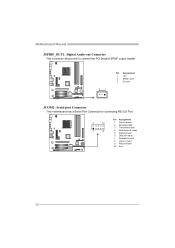
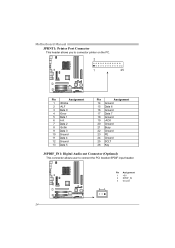
Motherboard Manual JSPDIF_OUT1: Digital Audio-out Connector This connector allows user to connect the PCI bracket SPDIF output header. 3 1 Pin Assignment 1 +5V 2 SPDIF_OUT 3 Ground JCOM1: Serial port Connector The motherboard has a Serial Port Connector for connecting RS-232 Port. 2 10 1 9 Pin Assignment 1 Carrier detect 2 Received data 3 Transmitted data 4 Data terminal ready 5 Signal ground 6 Data set ready 7 Request to send 8 Clear to send 9 Ring indicator 10 Key 22
Motherboard Manual JSPDIF_OUT1: Digital Audio-out Connector This connector allows user to connect the PCI bracket SPDIF output header. 3 1 Pin Assignment 1 +5V 2 SPDIF_OUT 3 Ground JCOM1: Serial port Connector The motherboard has a Serial Port Connector for connecting RS-232 Port. 2 10 1 9 Pin Assignment 1 Carrier detect 2 Received data 3 Transmitted data 4 Data terminal ready 5 Signal ground 6 Data set ready 7 Request to send 8 Clear to send 9 Ring indicator 10 Key 22

MANUAL
Page 23
TF7050-M2/TF7025-M2 PWRSW1 RSTSW1 PWRSW1: This is an on -board Power Switch button. RSTSW1: This is an on -board Reset button. LED_D1 LED_D2 LED_D1 and LED_D2: These 2 LED indicate system power on -board buttons. Please refer to show system status. On-Board Buttons There are 2 LED indicators on the motherboard to the table below for different messages: LED_D1 ON ON OFF OFF LED_D2 ON OFF ON OFF Message Normal Memory Error VGA Error Abnormal: CPU / Chipset error. 23 On-Board LED Indicators There are 2 on diagnostics.
TF7050-M2/TF7025-M2 PWRSW1 RSTSW1 PWRSW1: This is an on -board Power Switch button. RSTSW1: This is an on -board Reset button. LED_D1 LED_D2 LED_D1 and LED_D2: These 2 LED indicate system power on -board buttons. Please refer to show system status. On-Board Buttons There are 2 LED indicators on the motherboard to the table below for different messages: LED_D1 ON ON OFF OFF LED_D2 ON OFF ON OFF Message Normal Memory Error VGA Error Abnormal: CPU / Chipset error. 23 On-Board LED Indicators There are 2 on diagnostics.
MANUAL
Page 24
Motherboard Manual JPRNT1: Printer Port Connector This header allows you to connector printer on the PC. 2 1 25 Pin Assignment 1 -Strobe 2 -ALF 3 Data 0 4 -Error 5 Data 1 6 -Init 7 Data 2 8 -Scltin 9 Data 3 10 Ground 11 Data 4 12 Ground 13 Data 5 Pin Assignment 14 Ground 15 Data 6 16 Ground 17 Data 7 18 Ground 19 -ACK 20 Ground 21 Busy 22 Ground 23 PE 24 Ground 25 SCLT 26 Key JSPDIF_IN1: Digital Audio-out Connector (Optional) This connector allows user to connect the PCI bracket SPDIF input header. 3 1 Pin Assignment 1 +5V 2 SPDIF_IN 3 Ground 24
Motherboard Manual JPRNT1: Printer Port Connector This header allows you to connector printer on the PC. 2 1 25 Pin Assignment 1 -Strobe 2 -ALF 3 Data 0 4 -Error 5 Data 1 6 -Init 7 Data 2 8 -Scltin 9 Data 3 10 Ground 11 Data 4 12 Ground 13 Data 5 Pin Assignment 14 Ground 15 Data 6 16 Ground 17 Data 7 18 Ground 19 -ACK 20 Ground 21 Busy 22 Ground 23 PE 24 Ground 25 SCLT 26 Key JSPDIF_IN1: Digital Audio-out Connector (Optional) This connector allows user to connect the PCI bracket SPDIF input header. 3 1 Pin Assignment 1 +5V 2 SPDIF_IN 3 Ground 24
MANUAL
Page 26
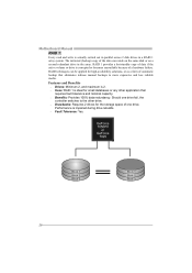
... corrupted or becomes unavailable because of a hardware failure. RAID techniques can reside on the same disk or on a second redundant drive in a RAID 1 array system. Motherboard Manual RAID 1: Every read and write is ideal for the storage space of one drive.
... corrupted or becomes unavailable because of a hardware failure. RAID techniques can reside on the same disk or on a second redundant drive in a RAID 1 array system. Motherboard Manual RAID 1: Every read and write is ideal for the storage space of one drive.
MANUAL
Page 28
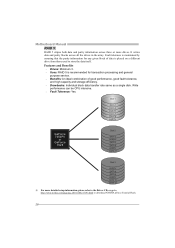
... 7050PV or GeForce 7025 Disk 2 DATA 2 PARITY DATA 5 DATA 8 PARITY DATA 11 Disk 3 PARITY DATA 4 DATA 6 PARITY DATA 10 DATA 12 ※ For more drives. Motherboard Manual RAID 5: RAID 5 stripes both data and parity information across all the drives in the array. Write performance can be CPU intensive. Fault Tolerance...
... 7050PV or GeForce 7025 Disk 2 DATA 2 PARITY DATA 5 DATA 8 PARITY DATA 11 Disk 3 PARITY DATA 4 DATA 6 PARITY DATA 10 DATA 12 ※ For more drives. Motherboard Manual RAID 5: RAID 5 stripes both data and parity information across all the drives in the array. Write performance can be CPU intensive. Fault Tolerance...

MANUAL
Page 30
Overclocking Navigator Engine (O.N.E.): ONE provides two powerful overclocking engines: MOS and AOS for experienced overclock users. Manual Overclock System (M.O.S.) MOS is designed for both Elite and Casual overclockers. It allows users to customize personal overclock settings. 30 Motherboard Manual 5.2 T-POWER BIOS FEATURE A.
Overclocking Navigator Engine (O.N.E.): ONE provides two powerful overclocking engines: MOS and AOS for experienced overclock users. Manual Overclock System (M.O.S.) MOS is designed for both Elite and Casual overclockers. It allows users to customize personal overclock settings. 30 Motherboard Manual 5.2 T-POWER BIOS FEATURE A.

