Setup Manual
Page 4
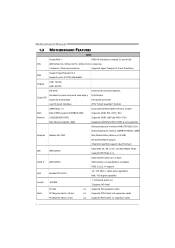
... used legacy Super I/O Super I/O functionality. SATA II AMD SB750 SATA Version 2.0 specification compliant. H/W Monitor Fan Speed Controller Low Pin Count Interface ITE's "Smart Guardian" function DIMM Slots x 4 Dual Channel Mode DDR2 memory module Main Each DIMM supports 256MB/512MB/ Supports DDR2 533 / 667 / 800 Memory 1GB/2GB/4GB DDR2 Supports DDR2 1066 (by AM2+ CPU) Max Memory Capicity 16GB Registered DIMM and ECC DIMM is not supported Onboard side port memory 64MB (TA790GX A2+) Onboard side port memory 128MB (TA790GX 128M) Graphics Radeon HD 3300 Max Shared Video Memory...
... used legacy Super I/O Super I/O functionality. SATA II AMD SB750 SATA Version 2.0 specification compliant. H/W Monitor Fan Speed Controller Low Pin Count Interface ITE's "Smart Guardian" function DIMM Slots x 4 Dual Channel Mode DDR2 memory module Main Each DIMM supports 256MB/512MB/ Supports DDR2 533 / 667 / 800 Memory 1GB/2GB/4GB DDR2 Supports DDR2 1066 (by AM2+ CPU) Max Memory Capicity 16GB Registered DIMM and ECC DIMM is not supported Onboard side port memory 64MB (TA790GX A2+) Onboard side port memory 128MB (TA790GX 128M) Graphics Radeon HD 3300 Max Shared Video Memory...
Setup Manual
Page 5
...digital audio in function CPU Fan header x1 CPU Fan power supply (with Smart Fan function) System Fan header x2 System Fan Power supply CMOS clear header x1 Restore CMOS data to factory default USB connector x3 Each connector supports 2 front panel USB ports Serial port Connector x1 Connects to RS-232 Port Power Connector (24pin) x1 Connects to Power supply Power Connector (4pin) x2 Connects to Power supply PS/2 Keyboard x1 Connects to PS/2 Keyboard PS/2 Mouse x1 Connects to PS/2 Mouse HDMI port x1 Connect to HDTV Back Panel VGA port x1 Connect to D-SUB monitor...
...digital audio in function CPU Fan header x1 CPU Fan power supply (with Smart Fan function) System Fan header x2 System Fan Power supply CMOS clear header x1 Restore CMOS data to factory default USB connector x3 Each connector supports 2 front panel USB ports Serial port Connector x1 Connects to RS-232 Port Power Connector (24pin) x1 Connects to Power supply Power Connector (4pin) x2 Connects to Power supply PS/2 Keyboard x1 Connects to PS/2 Keyboard PS/2 Mouse x1 Connects to PS/2 Mouse HDMI port x1 Connect to HDTV Back Panel VGA port x1 Connect to D-SUB monitor...

Setup Manual
Page 13
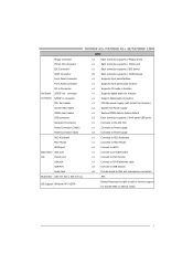
The IDE connector can connect a master and a slave drive, so you can connect up to two drives. 40 39 2 1 11 This connector supports the provided floppy drive ribbon cables. 2 34 1 33 IDE1: IDE/ATAPI Connector The motherboard has a 32-bit Enhanced IDE Controller that supports 360K, 720K, 1.2M, 1.44M and 2.88M floppy disk types. TA790GX A2+/TA790GX A2+ SE/TA790GX 128M 2.4 CONNECTORS AND SLOTS FDD1: Floppy Disk Connector The motherboard provides a standard floppy disk connector that provides PIO Mode 0~4, Bus Master, and Ultra DMA 33/66/100/133 functionality.
The IDE connector can connect a master and a slave drive, so you can connect up to two drives. 40 39 2 1 11 This connector supports the provided floppy drive ribbon cables. 2 34 1 33 IDE1: IDE/ATAPI Connector The motherboard has a 32-bit Enhanced IDE Controller that supports 360K, 720K, 1.2M, 1.44M and 2.88M floppy disk types. TA790GX A2+/TA790GX A2+ SE/TA790GX 128M 2.4 CONNECTORS AND SLOTS FDD1: Floppy Disk Connector The motherboard provides a standard floppy disk connector that provides PIO Mode 0~4, Bus Master, and Ultra DMA 33/66/100/133 functionality.
Setup Manual
Page 16
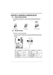
...on button 14 Motherboard Manual CHAPTER 3: HEADERS & JUMPERS SETUP 3.1 HOW TO SETUP JUMPERS The illustration shows how to connect the PC case's front panel switch functions. It allows user to set up jumpers. PWR_LED On/Off ++ - 9 16 1 +- 8 SPK RST HLED Pin Assignment 1 +5V 2 N/A 3 N/A 4 Speaker 5 HDD LED (+) 6 HDD LED (-) 7 Ground 8 Reset control Function Pin 9 Speaker 10 Connector 11 12 Hard drive 13 LED 14 Reset button 15 16 Assignment N/A N/A N/A Power LED (+) Power LED (+) Power LED (-) Power button Ground Function N/A N/A Power LED Power-on pins...
...on button 14 Motherboard Manual CHAPTER 3: HEADERS & JUMPERS SETUP 3.1 HOW TO SETUP JUMPERS The illustration shows how to connect the PC case's front panel switch functions. It allows user to set up jumpers. PWR_LED On/Off ++ - 9 16 1 +- 8 SPK RST HLED Pin Assignment 1 +5V 2 N/A 3 N/A 4 Speaker 5 HDD LED (+) 6 HDD LED (-) 7 Ground 8 Reset control Function Pin 9 Speaker 10 Connector 11 12 Hard drive 13 LED 14 Reset button 15 16 Assignment N/A N/A N/A Power LED (+) Power LED (+) Power LED (-) Power button Ground Function N/A N/A Power LED Power-on pins...

Setup Manual
Page 24
... n HD3650 Pair of CrossFireX function, please visit following web-sites: http://ati.amd.com/technology/crossfire/tutorials.html http://ati.amd.com/technology/crossfire/howitworksdemo.html 22 A power supply above 500W is recommended under CrossFireX mode. 4.2 CROSSFIREX INSTALLATION Step 1: Insert the two CrossFireX-Ready graphics cards into slots completely. Step 2: Connect a 4-pin ATX power cable to Auxiliary Power Connector (JATXPWR1), this will be unstable. A pair of your system.
... n HD3650 Pair of CrossFireX function, please visit following web-sites: http://ati.amd.com/technology/crossfire/tutorials.html http://ati.amd.com/technology/crossfire/howitworksdemo.html 22 A power supply above 500W is recommended under CrossFireX mode. 4.2 CROSSFIREX INSTALLATION Step 1: Insert the two CrossFireX-Ready graphics cards into slots completely. Step 2: Connect a 4-pin ATX power cable to Auxiliary Power Connector (JATXPWR1), this will be unstable. A pair of your system.

Setup Manual
Page 25
... 3: In the graphics card configuration program, choose "Hybrid CrossFireX" function. A power supply above 450W is recommended under Hybrid CrossFireX mode. 4.4 HYBRID CROSSFIREX INSTALLATION Step 1: Insert the Hybrid CrossFireX-Ready graphics card into PEX16_1 (Master), and insert the DCCFX-P2 Paddle Card into slots completely. Step 2: Connect a 4-pin ATX power cable to Auxiliary Power Connector (JATXPWR1), this will be unstable. The graphics card driver should support Hybrid CrossFireX technology. PEX16_2(S lave) DCCFX- TA790GX A2+/TA790GX A2+ SE/TA790GX 128M...
... 3: In the graphics card configuration program, choose "Hybrid CrossFireX" function. A power supply above 450W is recommended under Hybrid CrossFireX mode. 4.4 HYBRID CROSSFIREX INSTALLATION Step 1: Insert the Hybrid CrossFireX-Ready graphics card into PEX16_1 (Master), and insert the DCCFX-P2 Paddle Card into slots completely. Step 2: Connect a 4-pin ATX power cable to Auxiliary Power Connector (JATXPWR1), this will be unstable. The graphics card driver should support Hybrid CrossFireX technology. PEX16_2(S lave) DCCFX- TA790GX A2+/TA790GX A2+ SE/TA790GX 128M...
Setup Manual
Page 31
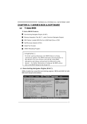
... from USB Flash Drive or FDD Self Recovery System (S.R.S) Smart Fan Function CMOS Reloading Program !! A. Main Advanced BIOS SETUP UTILITY PCIPnP Boot Chipset T-Series Exit T-Series Settings Options WARNING: Setting wrong values in below in the Setup CD. TA790GX A2+/TA790GX A2+ SE/TA790GX 128M CHAPTER 6: T-SERIES BIOS & SOFTWARE 6.1 T-SERIES BIOS T-Series BIOS Features Overclocking Navigator Engine (O.N.E.) Memory Integration Test (M.I.T., under Overclock Navigator Engine) BIO-Flasher: Update BIOS file from this manual is being continuously updated. Change Option F1...
... from USB Flash Drive or FDD Self Recovery System (S.R.S) Smart Fan Function CMOS Reloading Program !! A. Main Advanced BIOS SETUP UTILITY PCIPnP Boot Chipset T-Series Exit T-Series Settings Options WARNING: Setting wrong values in below in the Setup CD. TA790GX A2+/TA790GX A2+ SE/TA790GX 128M CHAPTER 6: T-SERIES BIOS & SOFTWARE 6.1 T-SERIES BIOS T-Series BIOS Features Overclocking Navigator Engine (O.N.E.) Memory Integration Test (M.I.T., under Overclock Navigator Engine) BIO-Flasher: Update BIOS file from this manual is being continuously updated. Change Option F1...
Setup Manual
Page 35
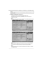
.... Main Advanced PCIPnP BIOS SETUP UTILITY Boot Chipset T-Series Exit T-Series Settings Options WARNING: Setting wrong values in below sections may cause system to test memory compatibilities, and no extra devices or software are needed. Enabled Disabled OverClock Navigator [Normal] =========== Automate OverClock System =========== Auto OverClock System [V6-Tech Engine] Manual OverClock System CPU Over Voltage [StartUp] Memory Over Voltage [1.95V] Chipset Over Voltage [1.15V] HT Over Voltage [1.20V] CPU Frequency [200] > CPU FID/VID Control > DRAM Timing...
.... Main Advanced PCIPnP BIOS SETUP UTILITY Boot Chipset T-Series Exit T-Series Settings Options WARNING: Setting wrong values in below sections may cause system to test memory compatibilities, and no extra devices or software are needed. Enabled Disabled OverClock Navigator [Normal] =========== Automate OverClock System =========== Auto OverClock System [V6-Tech Engine] Manual OverClock System CPU Over Voltage [StartUp] Memory Over Voltage [1.95V] Chipset Over Voltage [1.15V] HT Over Voltage [1.20V] CPU Frequency [200] > CPU FID/VID Control > DRAM Timing...

Setup Manual
Page 38
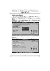
... Exit Options Save Changes and Exit Discard Changes and Exit Discard Changes Load Optimal Defaults CMOS Backup Function Security Settings > Security BIOS SETUP UTILITY Boot Chipset T-Series Exit CMOS Backup Func CMOS Data Reload CMOS Data Save Select Screen Select Item EnterGo to save different CMOS settings into BIOS-ROM. F. The range is lower than the set value, the CPU/System fan will turn off. Moreover, users are able to the set value, the CPU/ System fan will work when CPU/System temperature...
... Exit Options Save Changes and Exit Discard Changes and Exit Discard Changes Load Optimal Defaults CMOS Backup Function Security Settings > Security BIOS SETUP UTILITY Boot Chipset T-Series Exit CMOS Backup Func CMOS Data Reload CMOS Data Save Select Screen Select Item EnterGo to save different CMOS settings into BIOS-ROM. F. The range is lower than the set value, the CPU/System fan will turn off. Moreover, users are able to the set value, the CPU/ System fan will work when CPU/System temperature...

Setup Manual
Page 48
... internet before using this manual. 46 For better performance, the software is a new BIOS version, the utility will ask you to be slightly different from internet. Motherboard Manual (for AMI BIOS only) Automatically download and update the latest BIOS via internet; make any operation during the programing process. Click OK to enter BIOS setup. While the system boots up and the full screen logo shows, press key to...
... internet before using this manual. 46 For better performance, the software is a new BIOS version, the utility will ask you to be slightly different from internet. Motherboard Manual (for AMI BIOS only) Automatically download and update the latest BIOS via internet; make any operation during the programing process. Click OK to enter BIOS setup. While the system boots up and the full screen logo shows, press key to...

Setup Manual
Page 51
... are used for recovery 4 Flash Programming successful 5 File read error 7 No Flash EPROM detected 10 Flash Erase error 11 Flash Program error 12 "AMIBOOT.ROM" file size error 13 BIOS ROM image mismatch (file layout does not match image present in flash device) POST BIOS Beep Codes Number of Beeps Description 1 Memory refresh timer error 3 Base memory read/write test error 6 Keyboard controller BAT command failed 7 General exception error (processor exception interrupt error) 8 Display memory error (system video adapter) Troubleshooting POST BIOS Beep Codes Number...
... are used for recovery 4 Flash Programming successful 5 File read error 7 No Flash EPROM detected 10 Flash Erase error 11 Flash Program error 12 "AMIBOOT.ROM" file size error 13 BIOS ROM image mismatch (file layout does not match image present in flash device) POST BIOS Beep Codes Number of Beeps Description 1 Memory refresh timer error 3 Base memory read/write test error 6 Keyboard controller BAT command failed 7 General exception error (processor exception interrupt error) 8 Display memory error (system video adapter) Troubleshooting POST BIOS Beep Codes Number...
Bios Setup
Page 2
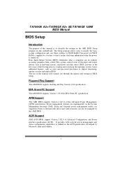
... in the ACPI specification, developed by Microso ft, Intel and T oshiba. 1 It provides ASL code for pow er manag ement and device con figuration capabilities as keyboard, mouse, serial ports and disk drives. Power management features are also included in BIOS. Sleep and Suspend power man agement modes are supported. Power to guide you through the options and settings in BIOS Setup. TA790GX A2+/TA790GX A2+ SE/TA790GX 128M BIOS Manual BIOS Setup Introduction T he purpose of this manual is turned off...
... in the ACPI specification, developed by Microso ft, Intel and T oshiba. 1 It provides ASL code for pow er manag ement and device con figuration capabilities as keyboard, mouse, serial ports and disk drives. Power management features are also included in BIOS. Sleep and Suspend power man agement modes are supported. Power to guide you through the options and settings in BIOS Setup. TA790GX A2+/TA790GX A2+ SE/TA790GX 128M BIOS Manual BIOS Setup Introduction T he purpose of this manual is turned off...

Bios Setup
Page 6
... Set the Smart Monitoring, Analysis, and Reporting T echnology. Type Select the type of the sub-menu. Options: Auto (Default) / Disabled / Enabled 5 SATA 1/2/3/4/5/6 Dev ice Main BIOS SETUP UTILITY Primary IDE Master Device : Type [Auto] LBA/Large Mode [Auto] Block (Multi-Sector Transfer)[Auto] PIO Mode [Auto] DMA Mode [Auto] S.M.A.R.T [Auto] 32Bit Data Transfer [Enabled] Select the type of device connected to the name of the IDE/SAT A drive. Options: Auto (Default) / Disabled Block (Multi-Sector Transfer) Enable or disable multi-sector trans fer. Change...
... Set the Smart Monitoring, Analysis, and Reporting T echnology. Type Select the type of the sub-menu. Options: Auto (Default) / Disabled / Enabled 5 SATA 1/2/3/4/5/6 Dev ice Main BIOS SETUP UTILITY Primary IDE Master Device : Type [Auto] LBA/Large Mode [Auto] Block (Multi-Sector Transfer)[Auto] PIO Mode [Auto] DMA Mode [Auto] S.M.A.R.T [Auto] 32Bit Data Transfer [Enabled] Select the type of device connected to the name of the IDE/SAT A drive. Options: Auto (Default) / Disabled Block (Multi-Sector Transfer) Enable or disable multi-sector trans fer. Change...

Bios Setup
Page 9
Options: Enabled (Default) / Disabled SuperIO Configuration Advan ced BIOS SETU P U TILITY Configure ITE8 718 Super IO Chipse t Onboard Floppy Controller Serial Port1 A ddress Parallel Port Address Parallel Por t Mode Parallel Por t IRQ Keyboard Power On Mouse PowerOn Restore on the system board and you wish to use it. Options: Enabled (Default) / Disabled 8 C hange Option F1 G eneral Help F10 S ave and Exit ESC E xit vxx .xx (C)Copyright 1985-200x, American Me gatrends, Inc. If...
Options: Enabled (Default) / Disabled SuperIO Configuration Advan ced BIOS SETU P U TILITY Configure ITE8 718 Super IO Chipse t Onboard Floppy Controller Serial Port1 A ddress Parallel Port Address Parallel Por t Mode Parallel Por t IRQ Keyboard Power On Mouse PowerOn Restore on the system board and you wish to use it. Options: Enabled (Default) / Disabled 8 C hange Option F1 G eneral Help F10 S ave and Exit ESC E xit vxx .xx (C)Copyright 1985-200x, American Me gatrends, Inc. If...

Bios Setup
Page 12
... the system temperature, fan speed, and voltage information. Options: Disabled (Default) / 60℃/140℉ / 65℃/149℉ / 70℃/158℉ / 75℃/167℉ / 80℃/176℉ / 85℃/185℉ / 90℃/194℉ 11 TA790GX A2+/TA790GX A2+ SE/TA790GX 128M BIOS Manual Fan Ctrl Start Value When CPU/System temperature arriv es to set value, the CPU/System fan will work under Windows 98 ACPI mode. Options: 1~127 Hardware...
... the system temperature, fan speed, and voltage information. Options: Disabled (Default) / 60℃/140℉ / 65℃/149℉ / 70℃/158℉ / 75℃/167℉ / 80℃/176℉ / 85℃/185℉ / 90℃/194℉ 11 TA790GX A2+/TA790GX A2+ SE/TA790GX 128M BIOS Manual Fan Ctrl Start Value When CPU/System temperature arriv es to set value, the CPU/System fan will work under Windows 98 ACPI mode. Options: 1~127 Hardware...

Bios Setup
Page 13
S elect Screen S elect Item +- Options: ACPI v1.0 (Default) / ACPI v2.0 ACPI APIC support T his item is used for System Suspend. Options: Enabled (Default) / Disabled 12 TA790GX A2+/TA790GX A2+ SE/TA790GX 128M BIOS Manual Power Configuration Advan ced BIOS SETU P U TILITY ACPI Settings Suspend mode ACPI Version F eatures ACPI APIC supp ort AMI OEMB table Headless mode RTC Resume RTC Alarm Date (Days) RTC Alarm Time USB Wakeup Fro m S3/S4 Power On by LA N [S1 (POS)] [ACP I v1.0] [Ena bled] [Ena...
S elect Screen S elect Item +- Options: ACPI v1.0 (Default) / ACPI v2.0 ACPI APIC support T his item is used for System Suspend. Options: Enabled (Default) / Disabled 12 TA790GX A2+/TA790GX A2+ SE/TA790GX 128M BIOS Manual Power Configuration Advan ced BIOS SETU P U TILITY ACPI Settings Suspend mode ACPI Version F eatures ACPI APIC supp ort AMI OEMB table Headless mode RTC Resume RTC Alarm Date (Days) RTC Alarm Time USB Wakeup Fro m S3/S4 Power On by LA N [S1 (POS)] [ACP I v1.0] [Ena bled] [Ena...

Bios Setup
Page 15
.../TA790GX 128M BIOS Manual USB Configuration T his item shows the USB controller and using such USB devices with operating systems that do not natively support USB (e.g. Select Screen Select Item +- Change Option F1 General Help F10 Save and Exit ESC Exit vxx.xx (C)Copyright 1985-200x, American Megatrends, Inc. Legacy USB Support T his item determines if the BIOS should provide legacy support fo r USB devices like the keyboard, mouse, and USB drive. Advanced BIOS SETUP UTILITY USB Configuration Module Version - 2.24.2-13.4 USB Devices Enabled: Legacy USB Support USB...
.../TA790GX 128M BIOS Manual USB Configuration T his item shows the USB controller and using such USB devices with operating systems that do not natively support USB (e.g. Select Screen Select Item +- Change Option F1 General Help F10 Save and Exit ESC Exit vxx.xx (C)Copyright 1985-200x, American Megatrends, Inc. Legacy USB Support T his item determines if the BIOS should provide legacy support fo r USB devices like the keyboard, mouse, and USB drive. Advanced BIOS SETUP UTILITY USB Configuration Module Version - 2.24.2-13.4 USB Devices Enabled: Legacy USB Support USB...

Bios Setup
Page 26
... the memory mode used for internal graphics. Options: Auto (Default) / 16M / 32M / 64M / 128M / 256M / 512M / Disabled GFX EngineClock Override T his item allows you to control the northbridge HD azalia (HDMI audio) function. Options: Enabled (Default) / Disabled 25 Options: Above 4G (Default) / Under 4G AMD 780 HD Audio T his item allows you to control the internal GFX engine clock override function. TA790GX A2+/TA790GX A2+ SE/TA790GX 128M BIOS Manual Internal Graphics Configuration BIOS SETU P U TILITY Chipset Internal Graph ics Configuration Internal Graph ics Mode...
... the memory mode used for internal graphics. Options: Auto (Default) / 16M / 32M / 64M / 128M / 256M / 512M / Disabled GFX EngineClock Override T his item allows you to control the northbridge HD azalia (HDMI audio) function. Options: Enabled (Default) / Disabled 25 Options: Above 4G (Default) / Under 4G AMD 780 HD Audio T his item allows you to control the internal GFX engine clock override function. TA790GX A2+/TA790GX A2+ SE/TA790GX 128M BIOS Manual Internal Graphics Configuration BIOS SETU P U TILITY Chipset Internal Graph ics Configuration Internal Graph ics Mode...

Bios Setup
Page 30
... T his item allows you to enable or disable the Onboard LAN Boot ROM. Options: Enable (Default) / Disable Realtek Option ROM T his option allows you to control the onboard LAN controller. MAC ID Information T his area shows the MAC ID. TA790GX A2+/TA790GX A2+ SE/TA790GX 128M BIOS Manual OnBoard Peripherals Configuration BIOS SETU P U TILITY Chipset MAC ID Informa tion Realtek PCIE N IC Realtek Optio n ROM [Ena ble] [Dis abled] Enable/Disable Onboard RTL8111C PCIE Network Controller S elect Screen S elect Item +- C hange Option F1 G eneral Help F10 S ave and...
... T his item allows you to enable or disable the Onboard LAN Boot ROM. Options: Enable (Default) / Disable Realtek Option ROM T his option allows you to control the onboard LAN controller. MAC ID Information T his area shows the MAC ID. TA790GX A2+/TA790GX A2+ SE/TA790GX 128M BIOS Manual OnBoard Peripherals Configuration BIOS SETU P U TILITY Chipset MAC ID Informa tion Realtek PCIE N IC Realtek Optio n ROM [Ena ble] [Dis abled] Enable/Disable Onboard RTL8111C PCIE Network Controller S elect Screen S elect Item +- C hange Option F1 G eneral Help F10 S ave and...
Bios Setup
Page 42
.... TA790GX A2+/TA790GX A2+ SE/TA790GX 128M BIOS Manual CMOS Backup Function It allows users to save an ideal overclock setting during overclock operation. Moreover, users are able to nam e the CMOS data acco rding to save different CMOS settings into BIOS-ROM and reload any saved CMOS setting for customizing system configurations. BIOS SETU P U TILITY Exit Security Setti ngs Supervisor Pas sword :Not Installe d User Password :Not Installe d Change Supervi sor Password User Access Le vel Change User Pa ssword Clear User Pas...
.... TA790GX A2+/TA790GX A2+ SE/TA790GX 128M BIOS Manual CMOS Backup Function It allows users to save an ideal overclock setting during overclock operation. Moreover, users are able to nam e the CMOS data acco rding to save different CMOS settings into BIOS-ROM and reload any saved CMOS setting for customizing system configurations. BIOS SETU P U TILITY Exit Security Setti ngs Supervisor Pas sword :Not Installe d User Password :Not Installe d Change Supervi sor Password User Access Le vel Change User Pa ssword Clear User Pas...


