
Setup Manual
Page 5
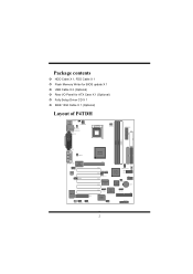
Package contents › HDD Cable X 1, FDD Cable X 1 › Flash Memory Writer for BIOS update X 1 › USB Cable X 2 (Optional) › Rear I/O Panel for ATX Case X 1 (Optional) › Fully Setup Driver CD X 1 › IEEE 1394 Cable X 1 (Optional) Layout of P4TDH K/B & Mouse JKBMS1 JKBV1 JATXPWR2 USB & LAN (Optional) JUSBV1 JRJ45USB1 JCOM1 JPRNT1 Socket 478 JCFAN1 JATXPWR1...
Package contents › HDD Cable X 1, FDD Cable X 1 › Flash Memory Writer for BIOS update X 1 › USB Cable X 2 (Optional) › Rear I/O Panel for ATX Case X 1 (Optional) › Fully Setup Driver CD X 1 › IEEE 1394 Cable X 1 (Optional) Layout of P4TDH K/B & Mouse JKBMS1 JKBV1 JATXPWR2 USB & LAN (Optional) JUSBV1 JRJ45USB1 JCOM1 JPRNT1 Socket 478 JCFAN1 JATXPWR1...
Setup Manual
Page 7
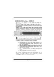
... DIMM Module (184 pin) Due to the limitation of chipset, this board only can support one DDR module and you are so many as possible. BIOSTAR would like to two double-sided*8 on DDR1/2. ; However, in DDR1 and 2 (blue color) Sockets. ※ DDR 3, white color sockets, only support ...※ Supports up to use the same type of modules including the model, speed and size of DDR memory. So we divide one bank into the sockets, we strongly suggest to 2 banks of memory. 4 For better compatibility, before insert DDR modules into 2 sockets. That means the bank just can support ...
... DIMM Module (184 pin) Due to the limitation of chipset, this board only can support one DDR module and you are so many as possible. BIOSTAR would like to two double-sided*8 on DDR1/2. ; However, in DDR1 and 2 (blue color) Sockets. ※ DDR 3, white color sockets, only support ...※ Supports up to use the same type of modules including the model, speed and size of DDR memory. So we divide one bank into the sockets, we strongly suggest to 2 banks of memory. 4 For better compatibility, before insert DDR modules into 2 sockets. That means the bank just can support ...
Setup Manual
Page 11
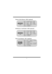
...: JMS1 (optional) 1 JMS1 Pin1 ==> Ground , Pin2 ==> MS1 Pin3 ==> 3.3V , Pin4 ==> MS2 Pin5 ==> MS3 , Pin6 ==> MS4 Pin7 ==> MS5 , Pin8 ==> MSCLK Pin9 ==> MSPWCTL# Pin10 ==> MSLED SD Memory Card Header: JSD1 (optional) 1 JSD1 Pin1 ==> Ground , Pin2 ==> SD1 Pin3 ==> 3.3V , Pin4 ==> SD2 Pin5 ==> SD3 , Pin6 ==> SD4 Pin7 ==> SD5 , Pin8 ==> SDCLK Pin9 ==> SDPWCTL# Pin10 ==> SDLED ...
...: JMS1 (optional) 1 JMS1 Pin1 ==> Ground , Pin2 ==> MS1 Pin3 ==> 3.3V , Pin4 ==> MS2 Pin5 ==> MS3 , Pin6 ==> MS4 Pin7 ==> MS5 , Pin8 ==> MSCLK Pin9 ==> MSPWCTL# Pin10 ==> MSLED SD Memory Card Header: JSD1 (optional) 1 JSD1 Pin1 ==> Ground , Pin2 ==> SD1 Pin3 ==> 3.3V , Pin4 ==> SD2 Pin5 ==> SD3 , Pin6 ==> SD4 Pin7 ==> SD5 , Pin8 ==> SDCLK Pin9 ==> SDPWCTL# Pin10 ==> SDLED ...
Setup Manual
Page 31
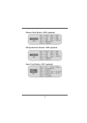
Memory Stick Header: JMS1 (optional) 1 JMS1 Pin1 ==> Masse , Pin2 ==> MS1 Pin3 ==> 3.3V , Pin4 ==> MS2 Pin5 ==> MS3 , Pin6 ==> MS4 Pin7 ==> MS5 , Pin8 ==> MSCLK Pin9 ==> MSPWCTL# Pin10 ==> MSLED ...
Memory Stick Header: JMS1 (optional) 1 JMS1 Pin1 ==> Masse , Pin2 ==> MS1 Pin3 ==> 3.3V , Pin4 ==> MS2 Pin5 ==> MS3 , Pin6 ==> MS4 Pin7 ==> MS5 , Pin8 ==> MSCLK Pin9 ==> MSPWCTL# Pin10 ==> MSLED ...

Setup Manual
Page 44
...™ ] technology assures the system stability by automatically rebooting the computer and then restart to power up CPU core voltage and Memory voltage. In addition, the frequency statuses of CPU, memory, AGP, and PCI along with just one . 41 Moreover, to protect users' computer systems if the setting is either the original...
...™ ] technology assures the system stability by automatically rebooting the computer and then restart to power up CPU core voltage and Memory voltage. In addition, the frequency statuses of CPU, memory, AGP, and PCI along with just one . 41 Moreover, to protect users' computer systems if the setting is either the original...
Setup Manual
Page 48
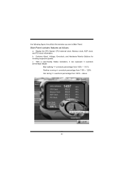
With a user-friendly Status Animation, it can represent 3 overclock percentage stages: Man walking => overclock percentage from 100% ~ 110 % Panther running => overclock percentage from 110% ~ 120% Car racing => overclock percentage from 120% ~ above 45 Contains About, Voltage, Overclock, and Hardware Monitor Buttons for invoking respective panels. b. the following figure; Display the CPU Speed, CPU external clock, Memory clock, AGP clock, and PCI clock information. the utility's first window you see is Main Panel. Main Panel contains features as follows: a. c.
With a user-friendly Status Animation, it can represent 3 overclock percentage stages: Man walking => overclock percentage from 100% ~ 110 % Panther running => overclock percentage from 110% ~ 120% Car racing => overclock percentage from 120% ~ above 45 Contains About, Voltage, Overclock, and Hardware Monitor Buttons for invoking respective panels. b. the following figure; Display the CPU Speed, CPU external clock, Memory clock, AGP clock, and PCI clock information. the utility's first window you see is Main Panel. Main Panel contains features as follows: a. c.
Setup Manual
Page 49
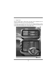
The default setting is "No". 3. In this panel, you click the option "Yes". 46 If you want to get the best performance of overclocking, we recommend you can decide to up as the following figure. Voltage Panel Click the Voltage button in Main Panel, the button will be highlighted and the Voltage Panel will slide out to increase CPU core voltage and Memory voltage or not.
The default setting is "No". 3. In this panel, you click the option "Yes". 46 If you want to get the best performance of overclocking, we recommend you can decide to up as the following figure. Voltage Panel Click the Voltage button in Main Panel, the button will be highlighted and the Voltage Panel will slide out to increase CPU core voltage and Memory voltage or not.
Bios Setup
Page 2
...BIOS. Power management features are supported. Sleep and Suspend power management modes are implemented via the System Management Interrupt (SMI). P4TDH BIOS Setup BIOS Setup Introduction This manual discussed Award™ Setup program built into the ROM BIOS. Adding important has customized the... is a custom version of this AWARD BIOS. 1 This special information is then stored in your computer system's ROM (Read Only Memory) is intended to modify the basic system configuration. APM Support These AWARD BIOS supports Version 1.1&1.2 of the EPA Green PC specification. ...
...BIOS. Power management features are supported. Sleep and Suspend power management modes are implemented via the System Management Interrupt (SMI). P4TDH BIOS Setup BIOS Setup Introduction This manual discussed Award™ Setup program built into the ROM BIOS. Adding important has customized the... is a custom version of this AWARD BIOS. 1 This special information is then stored in your computer system's ROM (Read Only Memory) is intended to modify the basic system configuration. APM Support These AWARD BIOS supports Version 1.1&1.2 of the EPA Green PC specification. ...
Bios Setup
Page 6
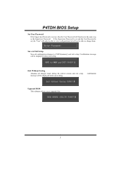
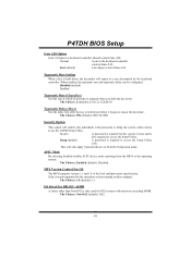
... This submenu allows you to upgrade bios. 5 Exit Without Saving Abandon all configuration changes to CMOS(memory) and exit setup. message will be able to change them. Confirmation message will be displayed before proceeding. P4TDH BIOS Setup Set User Password If the Supervisor Password is set , then the User Password will function...
... This submenu allows you to upgrade bios. 5 Exit Without Saving Abandon all configuration changes to CMOS(memory) and exit setup. message will be able to change them. Confirmation message will be displayed before proceeding. P4TDH BIOS Setup Set User Password If the Supervisor Password is set , then the User Password will function...
Bios Setup
Page 9
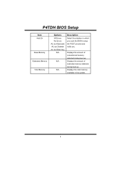
P4TDH BIOS Setup Item Halt On Base Memory Extended Memory Total Memory Options All Errors No Errors All, but Keyboard All, but Diskette All, but Disk/ Key N/A N/A N/A Description Select the situation in the system. 8 Displays the amount of extended memory detected during boot up . Displays the amount of conventional memory detected during boot up . Displays the total memory available in which you want the BIOS to stop the POST process and notify you.
P4TDH BIOS Setup Item Halt On Base Memory Extended Memory Total Memory Options All Errors No Errors All, but Keyboard All, but Diskette All, but Disk/ Key N/A N/A N/A Description Select the situation in the system. 8 Displays the amount of extended memory detected during boot up . Displays the amount of conventional memory detected during boot up . Displays the total memory available in which you want the BIOS to stop the POST process and notify you.
Bios Setup
Page 11
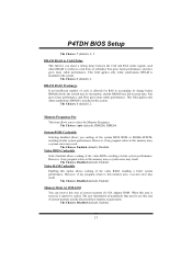
... supported by the keyboard controller. OS Select For DRAM > 64MB A choice other than Non-OS2 is required to repeat the keystroke. P4TDH BIOS Setup Gate A20 Option Select if chipset or keyboard controller should control Gate A20. When enabled, the typematic rate and typematic delay can...Choices: 250 (default), 500,750,1000. The Choices: 6 (default), 8,10,12,15,20,24,30. This will enable only individuals with memory exceeding 64MB. Typematic Rate Setting When a key is repeated when you hold the key down before it begins to access the Setup Utility only. The...
... supported by the keyboard controller. OS Select For DRAM > 64MB A choice other than Non-OS2 is required to repeat the keystroke. P4TDH BIOS Setup Gate A20 Option Select if chipset or keyboard controller should control Gate A20. When enabled, the typematic rate and typematic delay can...Choices: 250 (default), 500,750,1000. The Choices: 6 (default), 8,10,12,15,20,24,30. This will enable only individuals with memory exceeding 64MB. Typematic Rate Setting When a key is repeated when you hold the key down before it begins to access the Setup Utility only. The...

Bios Setup
Page 13
P4TDH BIOS Setup 4 Advanced Chipset Features This submenu allows you are suspicious that came with the PCI bus. This chipset manage bus speeds and access to ... This item controls the number of CAS latency depends on your system have been optimized and therefore should not be changed unless you to system memory resources, such as DRAM and external cache. The default settings that the settings have been changed incorrectly. „ Figure 4. The Choices: By SPD (default), Manual...
P4TDH BIOS Setup 4 Advanced Chipset Features This submenu allows you are suspicious that came with the PCI bus. This chipset manage bus speeds and access to ... This item controls the number of CAS latency depends on your system have been optimized and therefore should not be changed unless you to system memory resources, such as DRAM and external cache. The default settings that the settings have been changed incorrectly. „ Figure 4. The Choices: By SPD (default), Manual...
Bios Setup
Page 14
... Disabled (default), Enabled. 13 DRAM RAS# Precharge If an insufficient number of the video RAM, resulting a better system performance. Memory Frequency For This item allows you caching of the video BIOS, resulting a better system performance. Video BIOS Cacheable Select Enabled allows ... , read from, or refreshed. However, if any program writes to select the Memory Frequency. Fast gives faster performance; Video RAM Cacheable Enabling this option allows caching of cycle is installed in the system. P4TDH BIOS Setup The Choices: 7 (default), 6, 5. The Choices: 3 (default),...
... Disabled (default), Enabled. 13 DRAM RAS# Precharge If an insufficient number of the video RAM, resulting a better system performance. Memory Frequency For This item allows you caching of the video BIOS, resulting a better system performance. Video BIOS Cacheable Select Enabled allows ... , read from, or refreshed. However, if any program writes to select the Memory Frequency. Fast gives faster performance; Video RAM Cacheable Enabling this option allows caching of cycle is installed in the system. P4TDH BIOS Setup The Choices: 7 (default), 6, 5. The Choices: 3 (default),...
Bios Setup
Page 15
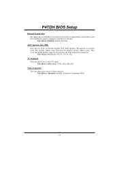
The Choices: Enabled (default), Disabled. AGP Aperture Size (MB) Select the size of the PCI memory address range dedicated for graphics memory address space. The Choices: 64 (default), 4, 8, 16, 32, 128, 256. Video Connector This item allows you to support delay transactions cycles. The...Standard This item allows you to the AGP without any translation. The apertures is a portion of the Accelerated Graphics Port (AGP) aperture. P4TDH BIOS Setup Delayed Transaction The chipset has an embedded 32-bit posted write buffer to select TV signal. Select Enabled to support compliance with...
The Choices: Enabled (default), Disabled. AGP Aperture Size (MB) Select the size of the PCI memory address range dedicated for graphics memory address space. The Choices: 64 (default), 4, 8, 16, 32, 128, 256. Video Connector This item allows you to support delay transactions cycles. The...Standard This item allows you to the AGP without any translation. The apertures is a portion of the Accelerated Graphics Port (AGP) aperture. P4TDH BIOS Setup Delayed Transaction The chipset has an embedded 32-bit posted write buffer to select TV signal. Select Enabled to support compliance with...
Bios Setup
Page 25
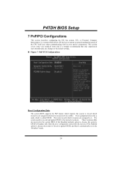
...The system BIOS supports the PnP feature which requires the system to record which resources are assigned to it is automatically set to the memory locations. This node records which resources are reserved in the system BIOS. PCI, or Personal Computer Interconnect, is a system which ...new configuration varies from conflict. Every peripheral device has a node, which allows I/O devices to the default settings. „ Figure 7. P4TDH BIOS Setup 7 PnP/PCI Configurations This section describes configuring the PCI bus system. This section covers some very technical items and it .
...The system BIOS supports the PnP feature which requires the system to record which resources are assigned to it is automatically set to the memory locations. This node records which resources are reserved in the system BIOS. PCI, or Personal Computer Interconnect, is a system which ...new configuration varies from conflict. Every peripheral device has a node, which allows I/O devices to the default settings. „ Figure 7. P4TDH BIOS Setup 7 PnP/PCI Configurations This section describes configuring the PCI bus system. This section covers some very technical items and it .


