
Setup Manual
Page 5
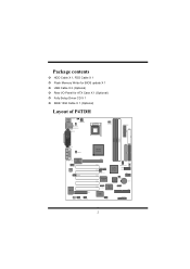
... › HDD Cable X 1, FDD Cable X 1 › Flash Memory Writer for BIOS update X 1 › USB Cable X 2 (Optional) › Rear I/O Panel for ATX Case X 1 (Optional) › Fully Setup Driver CD X 1 › IEEE 1394 Cable X 1 (Optional) Layout of P4TDH K/B & Mouse JKBMS1 JKBV1 JATXPWR2 USB & LAN (Optional) JUSBV1 JRJ45USB1 JCOM1 JPRNT1 Socket 478...CNR1 WOL1 J1394A1 J1394B1 AGP1 PCI1 JUSB4 JUSB3 PCI2 JUSBV3_4 PCI3 Winbond I/O PCI4 INTEL 82801DB (ICH4) JSFAN1 JDIMMVOLT JMS1 JSD1 JSC1 FWH BIOS JCMOS1 BAT1 PCI5 JSATA1 Serials ATA Controller JSATA2 IDE3 IEEE J1394C1 JPANEL1 2
... › HDD Cable X 1, FDD Cable X 1 › Flash Memory Writer for BIOS update X 1 › USB Cable X 2 (Optional) › Rear I/O Panel for ATX Case X 1 (Optional) › Fully Setup Driver CD X 1 › IEEE 1394 Cable X 1 (Optional) Layout of P4TDH K/B & Mouse JKBMS1 JKBV1 JATXPWR2 USB & LAN (Optional) JUSBV1 JRJ45USB1 JCOM1 JPRNT1 Socket 478...CNR1 WOL1 J1394A1 J1394B1 AGP1 PCI1 JUSB4 JUSB3 PCI2 JUSBV3_4 PCI3 Winbond I/O PCI4 INTEL 82801DB (ICH4) JSFAN1 JDIMMVOLT JMS1 JSD1 JSC1 FWH BIOS JCMOS1 BAT1 PCI5 JSATA1 Serials ATA Controller JSATA2 IDE3 IEEE J1394C1 JPANEL1 2
Setup Manual
Page 9
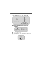
z Please set this header as "Open" while the voltage are adjusted via BIOS. Power Connectors: JATXPWR1/ JATXPWR2 JATXPWR2 (ATX 12V Power Conn.) JATXPWR1 (ATX Main Power Conn.) DIMM Power Selection Header: JDIMMVOLT (Optional) 1 2 12 JDIMMVOLT (Default ==> 2.56V) PPPPJPPPPuiiiiiiiinnnnnnnnm13571357p--------o24682468pooooooooeffffnnnnnffff 222222222.........678956789VVVVVVVVV z It is for over voltage function. Wake On LAN Header: WOL1 Ground 5V_SB Wake up 1 WOL1 6
z Please set this header as "Open" while the voltage are adjusted via BIOS. Power Connectors: JATXPWR1/ JATXPWR2 JATXPWR2 (ATX 12V Power Conn.) JATXPWR1 (ATX Main Power Conn.) DIMM Power Selection Header: JDIMMVOLT (Optional) 1 2 12 JDIMMVOLT (Default ==> 2.56V) PPPPJPPPPuiiiiiiiinnnnnnnnm13571357p--------o24682468pooooooooeffffnnnnnffff 222222222.........678956789VVVVVVVVV z It is for over voltage function. Wake On LAN Header: WOL1 Ground 5V_SB Wake up 1 WOL1 6

Setup Manual
Page 35
› HDD X 1、FDD X 1 › BIOS X 1 › USB X 2 ATX I/Oパネル X 1 CD X 1 › IEEE 1394 X 1 P4TDH JKBMS1 K /B と マウス JKBV1 JATXPWR2 USB と JUSBV1 AN JRJ45USB1 JCOM1 JPRNT1 JCFAN1 JATXPWR1 FDD1 COM1 DDR1 DDR2 DDR31 VGA1 JVGA1 JUSBV2 INTEL ... CODEC JCDIN1 CMI8738 CNR1 WOL1 J1394A1 J1394B1 AGP1 PCI1 JUSB4 JUSB3 PCI2 JUSBV3_4 PCI3 Winbond I/O PCI4 INTEL 82801DB (ICH4) JSFAN1 JDIMMVOLT JMS1 JSD1 JSC1 FWH BIOS JCMOS1 BAT1 PCI5 JSATA1 ATA JSATA2 IDE3 IEEE J1394C1 JPANEL1 32
› HDD X 1、FDD X 1 › BIOS X 1 › USB X 2 ATX I/Oパネル X 1 CD X 1 › IEEE 1394 X 1 P4TDH JKBMS1 K /B と マウス JKBV1 JATXPWR2 USB と JUSBV1 AN JRJ45USB1 JCOM1 JPRNT1 JCFAN1 JATXPWR1 FDD1 COM1 DDR1 DDR2 DDR31 VGA1 JVGA1 JUSBV2 INTEL ... CODEC JCDIN1 CMI8738 CNR1 WOL1 J1394A1 J1394B1 AGP1 PCI1 JUSB4 JUSB3 PCI2 JUSBV3_4 PCI3 Winbond I/O PCI4 INTEL 82801DB (ICH4) JSFAN1 JDIMMVOLT JMS1 JSD1 JSC1 FWH BIOS JCMOS1 BAT1 PCI5 JSATA1 ATA JSATA2 IDE3 IEEE J1394C1 JPANEL1 32

Setup Manual
Page 44
... protect users' computer systems if the setting is not appropriate when testing and results in the About panel, you can get the detailed descriptions about BIOS model and chipsets. In addition, the frequency statuses of CPU, memory, AGP, and PCI along with just one . 41 With the Overclock Manager, users can...
... protect users' computer systems if the setting is not appropriate when testing and results in the About panel, you can get the detailed descriptions about BIOS model and chipsets. In addition, the frequency statuses of CPU, memory, AGP, and PCI along with just one . 41 With the Overclock Manager, users can...
Setup Manual
Page 52
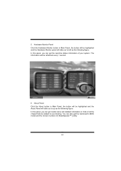
... can get model name and detailed information in Main Panel, the button will be refreshed every 1 second. 6. In this panel, you can get the mainboard's BIOS model and the Version number of all the chipset that are related to overclocking. 5. The information will slide out to left as the following figure...
... can get model name and detailed information in Main Panel, the button will be refreshed every 1 second. 6. In this panel, you can get the mainboard's BIOS model and the Version number of all the chipset that are related to overclocking. 5. The information will slide out to left as the following figure...

Bios Setup
Page 1
P4TDH BIOS Setup BIOS Setup 1 1 Main Menu 3 2 Standard CMOS Features 6 3 Advanced BIOS Features 9 4 Advanced Chipset Features 12 5 Integrated Peripherals 15 6 Power Management Setup 19 7 PnP/PCI Configurations 24 8 PC Health Status 27 9 Frequency Control 28 Special Feature: 9th Touch 30 i
P4TDH BIOS Setup BIOS Setup 1 1 Main Menu 3 2 Standard CMOS Features 6 3 Advanced BIOS Features 9 4 Advanced Chipset Features 12 5 Integrated Peripherals 15 6 Power Management Setup 19 7 PnP/PCI Configurations 24 8 PC Health Status 27 9 Frequency Control 28 Special Feature: 9th Touch 30 i
Bios Setup
Page 2
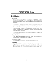
...Power to modify the basic system configuration. This means that it supports Intel Pentium ® 4 processor input/output system. The BIOS provides critical low-level support for detailed fine-tuning of configuring your system using Setup. The Setup program allows users to the hard...management modes are implemented via the System Management Interrupt (SMI). The Award BIOS™ installed in battery-backed RAM so that it retains the Setup information when the power is supported. P4TDH BIOS Setup BIOS Setup Introduction This manual discussed Award™ Setup program built into the ...
...Power to modify the basic system configuration. This means that it supports Intel Pentium ® 4 processor input/output system. The BIOS provides critical low-level support for detailed fine-tuning of configuring your system using Setup. The Setup program allows users to the hard...management modes are implemented via the System Management Interrupt (SMI). The Award BIOS™ installed in battery-backed RAM so that it retains the Setup information when the power is supported. P4TDH BIOS Setup BIOS Setup Introduction This manual discussed Award™ Setup program built into the ...

Bios Setup
Page 3
...by using the keyboard. Keystroke Up arrow Down arrow Left arrow Right arrow Move Enter PgUp key PgDn key + Key - Supported CPUs This AWARD BIOS supports the Intel Pentium ® 4 CPU. Key Esc key F1 key F5 key F6 key F7 key F10 key Function Move to previous ...item on Setup navigation keys Load previous values from CMOS Load the fail-safe defaults from BIOS default table Load the optimized defaults Save all the CMOS changes and exit 2 P4TDH BIOS Setup PCI Bus Support This AWARD BIOS also supports Version 2.1 of the Intel PCI (Peripheral Component Interconnect) local bus specification....
...by using the keyboard. Keystroke Up arrow Down arrow Left arrow Right arrow Move Enter PgUp key PgDn key + Key - Supported CPUs This AWARD BIOS supports the Intel Pentium ® 4 CPU. Key Esc key F1 key F5 key F6 key F7 key F10 key Function Move to previous ...item on Setup navigation keys Load previous values from CMOS Load the fail-safe defaults from BIOS default table Load the optimized defaults Save all the CMOS changes and exit 2 P4TDH BIOS Setup PCI Bus Support This AWARD BIOS also supports Version 2.1 of the Intel PCI (Peripheral Component Interconnect) local bus specification....
Bios Setup
Page 4
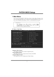
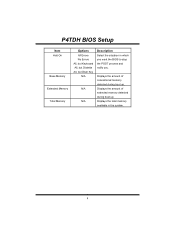
.... Advanced Chipset Features This submenu allows you to configure enhanced features of the BIOS. The Main Menu allows you to accept and enter the sub-menu. !! P4TDH BIOS Setup 1 Main Menu Once you enter Award BIOS™ CMOS Setup Utility, the Main Menu will appear on board, for ...reference, please refer to the BIOS installed on the screen. The information about BIOS defaults on manual (Figure 1,2,3,4,5,6,7,8,9) is just ...
.... Advanced Chipset Features This submenu allows you to configure enhanced features of the BIOS. The Main Menu allows you to accept and enter the sub-menu. !! P4TDH BIOS Setup 1 Main Menu Once you enter Award BIOS™ CMOS Setup Utility, the Main Menu will appear on board, for ...reference, please refer to the BIOS installed on the screen. The information about BIOS defaults on manual (Figure 1,2,3,4,5,6,7,8,9) is just ...

Bios Setup
Page 5
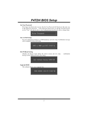
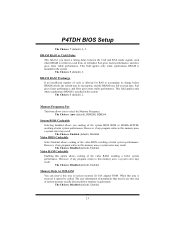
... change the voltage and clock may cause CPU or M/B damage!) Load Optimized Defaults This selection allows you to reload the BIOS when the system is strongly recommended not to use. Set Supervisor Password Setting the supervisor password will be prompted with the ... defaults are factory settings optimized for this function is having problems particularly with to enter a password. 4 These configurations are set. P4TDH BIOS Setup Integrated Peripherals This submenu allows you to configure certain "Plug and Play" and PCI options. PnP/PCI Configurations This submenu allows...
... change the voltage and clock may cause CPU or M/B damage!) Load Optimized Defaults This selection allows you to reload the BIOS when the system is strongly recommended not to use. Set Supervisor Password Setting the supervisor password will be prompted with the ... defaults are factory settings optimized for this function is having problems particularly with to enter a password. 4 These configurations are set. P4TDH BIOS Setup Integrated Peripherals This submenu allows you to configure certain "Plug and Play" and PCI options. PnP/PCI Configurations This submenu allows...
Bios Setup
Page 6
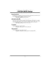
... Save all changes made during the current session and exit setup. Confirmation message will be displayed before proceeding. message will be displayed before proceeding. P4TDH BIOS Setup Set User Password If the Supervisor Password is set , then the User Password will not be able to change them. If the Supervisor ... set , the "User" will only be able to view configurations but will function in the same way as the Supervisor Password. confirmation Upgrade BIOS This submenu allows you to CMOS(memory) and exit setup. Exit Without Saving Abandon all configuration changes to upgrade...
... Save all changes made during the current session and exit setup. Confirmation message will be displayed before proceeding. message will be displayed before proceeding. P4TDH BIOS Setup Set User Password If the Supervisor Password is set , then the User Password will not be able to change them. If the Supervisor ... set , the "User" will only be able to view configurations but will function in the same way as the Supervisor Password. confirmation Upgrade BIOS This submenu allows you to CMOS(memory) and exit setup. Exit Without Saving Abandon all configuration changes to upgrade...
Bios Setup
Page 7
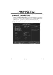
Each category includes no, one or more than one setup items. Use the arrow keys to highlight the item and then use the or keys to select the value you want in Standard CMOS Setup Menu are divided into 10 categories. Standard CMOS Setup 6 P4TDH BIOS Setup 2 Standard CMOS Features The items in each item. „ Figure 2.
Each category includes no, one or more than one setup items. Use the arrow keys to highlight the item and then use the or keys to select the value you want in Standard CMOS Setup Menu are divided into 10 categories. Standard CMOS Setup 6 P4TDH BIOS Setup 2 Standard CMOS Features The items in each item. „ Figure 2.
Bios Setup
Page 8
Time hh : mm : ss Set the system internal clock. sub menu of detailed options. sub menu of detailed options. CGA 80 MONO 7 P4TDH BIOS Setup Main Menu Selections This table shows the selections that the 'Day' automatically changes when you can make on the Main Menu. sub menu of ...
Time hh : mm : ss Set the system internal clock. sub menu of detailed options. sub menu of detailed options. CGA 80 MONO 7 P4TDH BIOS Setup Main Menu Selections This table shows the selections that the 'Day' automatically changes when you can make on the Main Menu. sub menu of ...
Bios Setup
Page 9
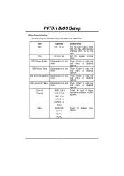
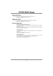
P4TDH BIOS Setup Item Halt On Base Memory Extended Memory Total Memory Options All Errors No Errors All, but Keyboard All, but Diskette All, but Disk/ Key N/A N/A N/A Description Select the situation in the system. 8 Displays the total memory available in which you want the BIOS to stop the POST process and notify you. Displays the amount of conventional memory detected during boot up . Displays the amount of extended memory detected during boot up .
P4TDH BIOS Setup Item Halt On Base Memory Extended Memory Total Memory Options All Errors No Errors All, but Keyboard All, but Diskette All, but Disk/ Key N/A N/A N/A Description Select the situation in the system. 8 Displays the total memory available in which you want the BIOS to stop the POST process and notify you. Displays the amount of conventional memory detected during boot up . Displays the amount of extended memory detected during boot up .
Bios Setup
Page 10
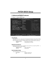
P4TDH BIOS Setup 3 Advanced BIOS Features „ Figure 3. Enabled Virus protection is arrow keys. 9 Off Numpad is activated. If this option will cause an abridged version of the Power On ... feature that is made to write to protect the IDE Hard Disk boot sector. Enabled (default) Enable quick POST. On (default) Numpad is disabled. Advanced BIOS Setup Virus Warning This option allows you power up the computer. Disabled (default) Virus protection is number keys. Boot Up NumLock Status Selects the NumLock...
P4TDH BIOS Setup 3 Advanced BIOS Features „ Figure 3. Enabled Virus protection is arrow keys. 9 Off Numpad is activated. If this option will cause an abridged version of the Power On ... feature that is made to write to protect the IDE Hard Disk boot sector. Enabled (default) Enable quick POST. On (default) Numpad is disabled. Advanced BIOS Setup Virus Warning This option allows you power up the computer. Disabled (default) Virus protection is number keys. Boot Up NumLock Status Selects the NumLock...
Bios Setup
Page 11
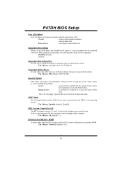
...Setup main menu. The Choices: 1.4 (default), 1.1. Normal A pin in the keyboard controller controls Gate A20. MPS Version Control For OS The BIOS supports version 1.1 and 1.4 of the Intel multiprocessor specification. Select version supported by the keyboard controller. Disabled (default) Enabled Typematic Rate (Chars/Sec)... which a keystroke is repeated when you hold the key down before it begins to access the Setup Utility. P4TDH BIOS Setup Gate A20 Option Select if chipset or keyboard controller should control Gate A20. Fast (default) Lets chipset control Gate A20.
...Setup main menu. The Choices: 1.4 (default), 1.1. Normal A pin in the keyboard controller controls Gate A20. MPS Version Control For OS The BIOS supports version 1.1 and 1.4 of the Intel multiprocessor specification. Select version supported by the keyboard controller. Disabled (default) Enabled Typematic Rate (Chars/Sec)... which a keystroke is repeated when you hold the key down before it begins to access the Setup Utility. P4TDH BIOS Setup Gate A20 Option Select if chipset or keyboard controller should control Gate A20. Fast (default) Lets chipset control Gate A20.
Bios Setup
Page 12
... Screen Show This item allows you to enable/ disable display the small EPA logo. Boot Seq & Floppy Setup First/ Second/ Third/ Boot Other Device These BIOS attempt to boot-up. Swap Floppy Drive For systems with two floppy drives, this option will test the floppy drives to determine if they have... system from the device in the sequence selected in these items. The Choices: Floppy, LS120, HDD-0, SCSI, CDROM, HDD-1, HDD-2, HDD-3, ZIP100, LAN, HPT370, Disabled. P4TDH BIOS Setup Small Logo(EPA) Show This item allows you to enable/ disable display the Summary Screen Show.
... Screen Show This item allows you to enable/ disable display the small EPA logo. Boot Seq & Floppy Setup First/ Second/ Third/ Boot Other Device These BIOS attempt to boot-up. Swap Floppy Drive For systems with two floppy drives, this option will test the floppy drives to determine if they have... system from the device in the sequence selected in these items. The Choices: Floppy, LS120, HDD-0, SCSI, CDROM, HDD-1, HDD-2, HDD-3, ZIP100, LAN, HPT370, Disabled. P4TDH BIOS Setup Small Logo(EPA) Show This item allows you to enable/ disable display the Summary Screen Show.

Bios Setup
Page 13
It also coordinates communications with your system. P4TDH BIOS Setup 4 Advanced Chipset Features This submenu allows you are suspicious that came with the PCI bus. Active to Precharge Delay This item controls the number ...
It also coordinates communications with your system. P4TDH BIOS Setup 4 Advanced Chipset Features This submenu allows you are suspicious that came with the PCI bus. Active to Precharge Delay This item controls the number ...
Bios Setup
Page 14
...data. When this memory area, a system error may result. The Choices: 3 (default), 2. The Choices: Enabled (default), Disabled. Video BIOS Cacheable Select Enabled allows caching of system memory for RAS to select the Memory Frequency. The Choices: Disabled (default), Enabled. Fast gives faster performance... strobe signals, used when DRAM is allowed for ISA adapter ROM. Fast gives faster performance; P4TDH BIOS Setup The Choices: 7 (default), 6, 5. System BIOS Cacheable Selecting Enabled allows you to accumulate its charge before DRAM refresh, the refresh may result.
...data. When this memory area, a system error may result. The Choices: 3 (default), 2. The Choices: Enabled (default), Disabled. Video BIOS Cacheable Select Enabled allows caching of system memory for RAS to select the Memory Frequency. The Choices: Disabled (default), Enabled. Fast gives faster performance... strobe signals, used when DRAM is allowed for ISA adapter ROM. Fast gives faster performance; P4TDH BIOS Setup The Choices: 7 (default), 6, 5. System BIOS Cacheable Selecting Enabled allows you to accumulate its charge before DRAM refresh, the refresh may result.
Bios Setup
Page 15
... dedicated for graphics memory address space. Select Enabled to the AGP without any translation. Video Connector This item allows you to support delay transactions cycles. P4TDH BIOS Setup Delayed Transaction The chipset has an embedded 32-bit posted write buffer to select TV signal. The Choices: 64 (default), 4, 8, 16, 32, 128, 256...
... dedicated for graphics memory address space. Select Enabled to the AGP without any translation. Video Connector This item allows you to support delay transactions cycles. P4TDH BIOS Setup Delayed Transaction The chipset has an embedded 32-bit posted write buffer to select TV signal. The Choices: 64 (default), 4, 8, 16, 32, 128, 256...

