
User Manual
Page 2
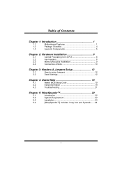
...Package Checklist 4 1.3 Layout & Components 5 Chapter 2: Hardware Installation 6 2.1 Central Processing Unit (CPU 6 2.2 Fan Headers 8 2.3 Memory Modules Installation 9 2.4 Connectors & Slots 10 Chapter 3: Headers & Jumpers Setup 12 3.1 How to setup Jumpers 12 3.2 Detail Settings 12 Chapter 4: Useful Help 19 4.1 Award BIOS Beep Code 19 4.2 Extra Information 19 4.3 Troubleshooting 21 Chapter 5: WarpSpeeder 22 5.1 Introduction 22 5.2 System Requirement 22 5.3 Installation 23 5.4 [WarpSpeeder™] includes 1 tray icon and 5 panels....... 24 ii
...Package Checklist 4 1.3 Layout & Components 5 Chapter 2: Hardware Installation 6 2.1 Central Processing Unit (CPU 6 2.2 Fan Headers 8 2.3 Memory Modules Installation 9 2.4 Connectors & Slots 10 Chapter 3: Headers & Jumpers Setup 12 3.1 How to setup Jumpers 12 3.2 Detail Settings 12 Chapter 4: Useful Help 19 4.1 Award BIOS Beep Code 19 4.2 Extra Information 19 4.3 Troubleshooting 21 Chapter 5: WarpSpeeder 22 5.1 Introduction 22 5.2 System Requirement 22 5.3 Installation 23 5.4 [WarpSpeeder™] includes 1 tray icon and 5 panels....... 24 ii

User Manual
Page 3
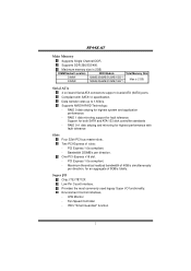
... (L) On-board IDE 2 on-board connectors support 4 IDE disk drives. Supports AMD Athlon 64 and Sempron processors. Supports NVIDIA nTune Utility. - Complaints with PCI-Express Version 1.a specification. Supports 1 PCI-Express x16 interface graphics slot. - Chipset NVIDIA nForce4 4X: - Supports 4 SATA ports, each channel up to 1.5Gb/s. - Supports SCO UNIX. NF44X-A7 CHAPTER 1: INTRODUCTION 1.1 MOTHERBOARD FEATURES A. Supports HyperTransport Technology and AMD Cool'n'Quiet Technology. AMD 64 architecture enables simultaneous 32 and 64 bit computing. Supports NVIDIA RAID functions...
... (L) On-board IDE 2 on-board connectors support 4 IDE disk drives. Supports AMD Athlon 64 and Sempron processors. Supports NVIDIA nTune Utility. - Complaints with PCI-Express Version 1.a specification. Supports 1 PCI-Express x16 interface graphics slot. - Chipset NVIDIA nForce4 4X: - Supports 4 SATA ports, each channel up to 1.5Gb/s. - Supports SCO UNIX. NF44X-A7 CHAPTER 1: INTRODUCTION 1.1 MOTHERBOARD FEATURES A. Supports HyperTransport Technology and AMD Cool'n'Quiet Technology. AMD 64 architecture enables simultaneous 32 and 64 bit computing. Supports NVIDIA RAID functions...
User Manual
Page 4
... RAID Technology: - RAID 0 disk striping for highest performance with SATA1.0 specification. RAID 0+1 disk striping and mirroring for highest system and application performance - Environment Control initiatives, - DIMM Socket Location DDR Module Total Memory Size DIMM1 DIMM2 128MB/256MB/512MB/1GB *1 128MB/256MB/512MB/1GB *1 Max is 2GB. Provides the most commonly used legacy Super I /O Chip: ITE IT8712F. One PCI-Express x16 slot. - Maximum theoretical realized bandwidth of 8GB/s totally. NF44X-A7 Main Memory Supports...
... RAID Technology: - RAID 0 disk striping for highest performance with SATA1.0 specification. RAID 0+1 disk striping and mirroring for highest system and application performance - Environment Control initiatives, - DIMM Socket Location DDR Module Total Memory Size DIMM1 DIMM2 128MB/256MB/512MB/1GB *1 128MB/256MB/512MB/1GB *1 Max is 2GB. Provides the most commonly used legacy Super I /O Chip: ITE IT8712F. One PCI-Express x16 slot. - Maximum theoretical realized bandwidth of 8GB/s totally. NF44X-A7 Main Memory Supports...

User Manual
Page 5
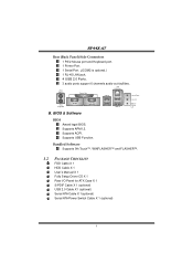
...88Mbytes. 2 IDE connectors support 4 IDE disk drives. 3 USB headers support 6 USB 2.0 ports at front panel. 4 Serial ATA connectors support 4 SATA devices. 3 Environment Control initiatives: - Fan Speed Controller, - Security NVIDIA Firewall technology - Remote access, configuration, monitoring - Native firewall solution Advanced features - H/W Monitor, - Supports 6 channels audio output. 10/100 LAN Chip: RTL8201BL / RTL8201CL. WMI scripts. NF44X-A7 On-board AC'97 Audio Sound Codec Chip: ALC655: - Internal On-board Connectors and Headers 1 audio-out header supports audio-out...
...88Mbytes. 2 IDE connectors support 4 IDE disk drives. 3 USB headers support 6 USB 2.0 ports at front panel. 4 Serial ATA connectors support 4 SATA devices. 3 Environment Control initiatives: - Fan Speed Controller, - Security NVIDIA Firewall technology - Remote access, configuration, monitoring - Native firewall solution Advanced features - H/W Monitor, - Supports 6 channels audio output. 10/100 LAN Chip: RTL8201BL / RTL8201CL. WMI scripts. NF44X-A7 On-board AC'97 Audio Sound Codec Chip: ALC655: - Internal On-board Connectors and Headers 1 audio-out header supports audio-out...
User Manual
Page 6
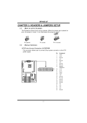
...; and FLASHER™. 1.2 PACKAGE CHECKLIST FDD Cable X 1 HDD Cable X 1 User's Manual X 1 Fully Setup Driver CD X 1 Rear I/O Panel for ATX Case X 1 S/PDIF Cable X 1 (optional) USB 2.0 Cable X1 (optional) Serial ATA Cable X 1(optional) Serial ATA Power Switch Cable X 1 (optional) 4 NF44X-A7 Rear (Back Panel) Side Connectors 1 PS/2 Mouse port and Keyboard port. 1 Printer Port. 1 Serial Port. (JCOM2 is optional.) 1 RJ-45 LAN jack. 4 USB 2.0 Ports. 3 audio ports support 6 channels audio-out facilities. BIOS & Software BIOS Award legal BIOS. Supports APM1.2. Supports ACPI.
...; and FLASHER™. 1.2 PACKAGE CHECKLIST FDD Cable X 1 HDD Cable X 1 User's Manual X 1 Fully Setup Driver CD X 1 Rear I/O Panel for ATX Case X 1 S/PDIF Cable X 1 (optional) USB 2.0 Cable X1 (optional) Serial ATA Cable X 1(optional) Serial ATA Power Switch Cable X 1 (optional) 4 NF44X-A7 Rear (Back Panel) Side Connectors 1 PS/2 Mouse port and Keyboard port. 1 Printer Port. 1 Serial Port. (JCOM2 is optional.) 1 RJ-45 LAN jack. 4 USB 2.0 Ports. 3 audio ports support 6 channels audio-out facilities. BIOS & Software BIOS Award legal BIOS. Supports APM1.2. Supports ACPI.
User Manual
Page 7
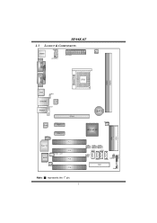
NF44X-A7 1.3 LAYOUT & COMPONENTS JKBMSV1 JKBMS1 JATXPWR2 JATXPWR1 JCFAN1 JCOM1 JPRNT1 Socket 754 JCOM2 (optional) CPU1 DIMM2 DIMM1 JUSB1 JUSBV1 JUSBLAN1 LAN JFAUDIO1 JAUDIO1 PEX16 Codec PEX1_1 JCDIN1 Super I/O BIOS PEX1_2 JSPDIF_OUT1 PCI1 PCI2 PCI3 JSFAN1 PCI4 BAT1 JNBFAN1 nForce4 4X IDE1 IDE2 JUSB2 JUSB3 JUSB4 JSATA1 JSATA3 JUSBV2 JCI1 JSATA2 JCMOS1 JSATA4 FDD1 JPANEL1 Note: ■ represents the 1st pin. 5 (optional)
NF44X-A7 1.3 LAYOUT & COMPONENTS JKBMSV1 JKBMS1 JATXPWR2 JATXPWR1 JCFAN1 JCOM1 JPRNT1 Socket 754 JCOM2 (optional) CPU1 DIMM2 DIMM1 JUSB1 JUSBV1 JUSBLAN1 LAN JFAUDIO1 JAUDIO1 PEX16 Codec PEX1_1 JCDIN1 Super I/O BIOS PEX1_2 JSPDIF_OUT1 PCI1 PCI2 PCI3 JSFAN1 PCI4 BAT1 JNBFAN1 nForce4 4X IDE1 IDE2 JUSB2 JUSB3 JUSB4 JSATA1 JSATA3 JUSBV2 JCI1 JSATA2 JCMOS1 JSATA4 FDD1 JPANEL1 Note: ■ represents the 1st pin. 5 (optional)

User Manual
Page 10
When connecting with Smart Fan Control utility. NF44X-A7 2.2 FAN HEADERS CPU FAN Power Header: JCFAN1 System Fan Power Header: JSFAN1 Northbridge Fan Power Header: JNBFAN1 JCFAN1 13 JNBFAN1 Pin Assignment 1 Ground 2 +12V 3 FAN RPM rate sense (Only for JCFAN1 and JSFAN1.) 31 JSFAN1 3 1 Note: The JCFAN1 and JSFAN1 support system cooling fan with wires onto connectors, please note that the red wire is the positive and should be connected to pin#2, and the black wire is Ground and should be connected to GND. 8 It supports 3 pin head connector.
When connecting with Smart Fan Control utility. NF44X-A7 2.2 FAN HEADERS CPU FAN Power Header: JCFAN1 System Fan Power Header: JSFAN1 Northbridge Fan Power Header: JNBFAN1 JCFAN1 13 JNBFAN1 Pin Assignment 1 Ground 2 +12V 3 FAN RPM rate sense (Only for JCFAN1 and JSFAN1.) 31 JSFAN1 3 1 Note: The JCFAN1 and JSFAN1 support system cooling fan with wires onto connectors, please note that the red wire is the positive and should be connected to pin#2, and the black wire is Ground and should be connected to GND. 8 It supports 3 pin head connector.
User Manual
Page 12
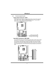
... hard drive should always be connected to four hard disk drives. IDE1 IDE2 40 39 2 1 10 NF44X-A7 2.4 CONNECTORS & SLOTS Floppy Disk Connector: FDD1 The motherboard provides a standard floppy disk connector that provides PIO Mode 0~5, Bus Master, and Ultra DMA 33/66/100/133 functionality. This connector supports the provided floppy drive ribbon cables. 2 34 1 33 Hard Disk Connectors: IDE1/IDE2 The motherboard has two 32-bit Enhanced PCI IDE Controller that supports 360K, 720K, 1.2M, 1.44M and 2.88M floppy disk types. It has two HDD connectors...
... hard drive should always be connected to four hard disk drives. IDE1 IDE2 40 39 2 1 10 NF44X-A7 2.4 CONNECTORS & SLOTS Floppy Disk Connector: FDD1 The motherboard provides a standard floppy disk connector that provides PIO Mode 0~5, Bus Master, and Ultra DMA 33/66/100/133 functionality. This connector supports the provided floppy drive ribbon cables. 2 34 1 33 Hard Disk Connectors: IDE1/IDE2 The motherboard has two 32-bit Enhanced PCI IDE Controller that supports 360K, 720K, 1.2M, 1.44M and 2.88M floppy disk types. It has two HDD connectors...
User Manual
Page 14
Pin opened 3.2 DETAIL SETTINGS Pin closed Pin1-2 closed ATX Power Source Connector: JATXPWR1 This connector allows user to set up jumpers. NF44X-A7 CHAPTER 3: HEADERS & JUMPERS SETUP 3.1 HOW TO SETUP JUMPERS The illustration shows how to connect 24-pin power connector on pins, the jumper is "close", if not, that means the jumper is placed on the ATX power supply. Pin Assignment 1 +3.3V 2 +3.3V 3 Ground 4 +5V 5 Ground 6 +5V 7 Ground 8 PW_OK 9 Standby Voltage+5V 24 13 10 +12V 12 1 11...
Pin opened 3.2 DETAIL SETTINGS Pin closed Pin1-2 closed ATX Power Source Connector: JATXPWR1 This connector allows user to set up jumpers. NF44X-A7 CHAPTER 3: HEADERS & JUMPERS SETUP 3.1 HOW TO SETUP JUMPERS The illustration shows how to connect 24-pin power connector on pins, the jumper is "close", if not, that means the jumper is placed on the ATX power supply. Pin Assignment 1 +3.3V 2 +3.3V 3 Ground 4 +5V 5 Ground 6 +5V 7 Ground 8 PW_OK 9 Standby Voltage+5V 24 13 10 +12V 12 1 11...
User Manual
Page 15
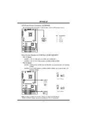
NF44X-A7 ATX Power Source Connector: JATXPWR2 By connecting this connector, it will provide +12V to support this function "Power-on system via USB device," "JUSBV1/JUSBV2" jumper cap should be placed on Pin 2-3 individually. 13 JUSBV2: +5V for USB ports at JUSB1 and JUSBLAN1 are powered with +5V standby voltage. Pin 2-3 Close: JUSBV1: USB ports at JUSB1 and JUSBLAN1. JUSBV2: Front USB headers (JUSB2/JUSB3/JUSB4) are powered with +5V standby voltage. 3 13...
NF44X-A7 ATX Power Source Connector: JATXPWR2 By connecting this connector, it will provide +12V to support this function "Power-on system via USB device," "JUSBV1/JUSBV2" jumper cap should be placed on Pin 2-3 individually. 13 JUSBV2: +5V for USB ports at JUSB1 and JUSBLAN1 are powered with +5V standby voltage. Pin 2-3 Close: JUSBV1: USB ports at JUSB1 and JUSBLAN1. JUSBV2: Front USB headers (JUSB2/JUSB3/JUSB4) are powered with +5V standby voltage. 3 13...
User Manual
Page 16
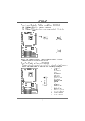
... Panel Audio-out Header: JFAUDIO1 This connector will disable the output on the PC case. It will allow user to connect with +5V standby voltage. 13 13 Pin 1-2 close 13 Pin 2-3 close Note: In order to support this function "Power-on system via keyboard and mouse", "JKBMSV1" jumper cap should be placed on Pin 2-3. NF44X-A7 Power Source Header for PS/2 Keyboard/Mouse: JKBMSV1 Pin 1-2 Close: +5V for PS/2 keyboard and mouse. Pin...
... Panel Audio-out Header: JFAUDIO1 This connector will disable the output on the PC case. It will allow user to connect with +5V standby voltage. 13 13 Pin 1-2 close 13 Pin 2-3 close Note: In order to support this function "Power-on system via keyboard and mouse", "JKBMSV1" jumper cap should be placed on Pin 2-3. NF44X-A7 Power Source Header for PS/2 Keyboard/Mouse: JKBMSV1 Pin 1-2 Close: +5V for PS/2 keyboard and mouse. Pin...

User Manual
Page 17
If the signal has been triggered, it will record to monitor PC case open signal 2 Ground 15 Pin Assignment 1 Left channel input 2 Ground 3 Ground 4 Right channel input 4 1 Case Open Headers: JCI1 This connector allows system to the CMOS and show the message on next boot-up. NF44X-A7 CD-ROM Audio-in Connector: JCDIN1 This connector allows user to connect the audio source from the variety devices, like CD-ROM, DVD-ROM, PCI sound card, PCI TV turner card etc.. JCI1 12 Pin Assignment 1 Case open status.
If the signal has been triggered, it will record to monitor PC case open signal 2 Ground 15 Pin Assignment 1 Left channel input 2 Ground 3 Ground 4 Right channel input 4 1 Case Open Headers: JCI1 This connector allows system to the CMOS and show the message on next boot-up. NF44X-A7 CD-ROM Audio-in Connector: JCDIN1 This connector allows user to connect the audio source from the variety devices, like CD-ROM, DVD-ROM, PCI sound card, PCI TV turner card etc.. JCI1 12 Pin Assignment 1 Case open status.

User Manual
Page 18
JUSB2 2 10 1 9 JUSB3 Pin Assignment 1 +5V (fused) 2 +5V (fused) 3 USB4 USB5 USB+ 6 USB+ 7 Ground 8 Ground JUSB4 9 Key 10 NC 16 NF44X-A7 Digital Audio-out Connector: JSPDIF_OUT1 These connectors allow user to connect additional USB cables at PC front panel, and also can be connected with internal USB devices, like USB card reader. Pin Assignment 1 +5V 2 SPDIF OUT 3 Ground 3 1 Headers for USB Ports at Front Panel: JUSB2~JUSB4 This connector allows user to connect the PCI bracket SPDIF output or input header.
JUSB2 2 10 1 9 JUSB3 Pin Assignment 1 +5V (fused) 2 +5V (fused) 3 USB4 USB5 USB+ 6 USB+ 7 Ground 8 Ground JUSB4 9 Key 10 NC 16 NF44X-A7 Digital Audio-out Connector: JSPDIF_OUT1 These connectors allow user to connect additional USB cables at PC front panel, and also can be connected with internal USB devices, like USB card reader. Pin Assignment 1 +5V 2 SPDIF OUT 3 Ground 3 1 Headers for USB Ports at Front Panel: JUSB2~JUSB4 This connector allows user to connect the PCI bracket SPDIF output or input header.
User Manual
Page 19
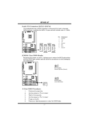
Set the jumper to "Pin 1-2 close". 5. Remove AC power line. 2. Set the jumper to "Pin 2-3 close : Clear CMOS data. 13 ※ Clear CMOS Procedures: 1. Power on pin2-3, it satisfies the SATA 1.0 spec and with transfer rate of 1.5Gb/s. Reset your desired password or clear the CMOS data. 17 Wait for five seconds. 4. NF44X-A7 Serial ATA Connectors: JSATA1~JSATA4 The motherboard has a SATA Controller in nForce4 4X SLI with 4 channels SATA interface, it allows user to restore the BIOS safe setting and the CMOS data...
Set the jumper to "Pin 1-2 close". 5. Remove AC power line. 2. Set the jumper to "Pin 2-3 close : Clear CMOS data. 13 ※ Clear CMOS Procedures: 1. Power on pin2-3, it satisfies the SATA 1.0 spec and with transfer rate of 1.5Gb/s. Reset your desired password or clear the CMOS data. 17 Wait for five seconds. 4. NF44X-A7 Serial ATA Connectors: JSATA1~JSATA4 The motherboard has a SATA Controller in nForce4 4X SLI with 4 channels SATA interface, it allows user to restore the BIOS safe setting and the CMOS data...

User Manual
Page 20
... optional 24 23 Pin Assignment 1 +5V 3 N/A 5 N/A 7 Speaker 9 HDD LED (+) 11 HDD LED (-) 13 Ground 15 Reset control 17 N/A 19 N/A 21 +5V 23 IRTX Function Speaker Connector Hard drive LED Reset button IrDA Connector (optional) 21 Pin Assignment 2 Sleep control 4 Ground 6 N/A 8 Power LED (+) 10 Power LED (+) 12 Power LED (-) 14 Power button 16 Ground 18 Key 20 Key 22 Ground 24 IRRX Function Sleep button N/A Power LED Power-on , Reset, HDD LED, Power LED, Sleep button, speaker and IrDA Connection. It allows user to connect the PC case's front panel switch functions...
... optional 24 23 Pin Assignment 1 +5V 3 N/A 5 N/A 7 Speaker 9 HDD LED (+) 11 HDD LED (-) 13 Ground 15 Reset control 17 N/A 19 N/A 21 +5V 23 IRTX Function Speaker Connector Hard drive LED Reset button IrDA Connector (optional) 21 Pin Assignment 2 Sleep control 4 Ground 6 N/A 8 Power LED (+) 10 Power LED (+) 12 Power LED (-) 14 Power button 16 Ground 18 Key 20 Key 22 Ground 24 IRRX Function Sleep button N/A Power LED Power-on , Reset, HDD LED, Power LED, Sleep button, speaker and IrDA Connection. It allows user to connect the PC case's front panel switch functions...
User Manual
Page 21
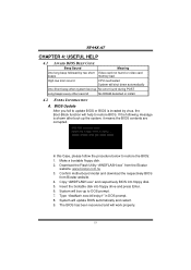
... floppy drive and press Enter. 6. Type "Awdflash xxxx.bf/sn/py/r" in DOS prompt. 8. If the following message is invaded by two short Video card not found or video card beeps memory bad High-low siren sound CPU overheated System will shut down automatically One Short beep when system boot-up No error found during POST Long beeps every other second No DRAM detected or install 4.2 EXTRA INFORMATION A. NF44X-A7 CHAPTER 4: USEFUL HELP 4.1 AWARD BIOS BEEP CODE Beep Sound Meaning One long beep...
... floppy drive and press Enter. 6. Type "Awdflash xxxx.bf/sn/py/r" in DOS prompt. 8. If the following message is invaded by two short Video card not found or video card beeps memory bad High-low siren sound CPU overheated System will shut down automatically One Short beep when system boot-up No error found during POST Long beeps every other second No DRAM detected or install 4.2 EXTRA INFORMATION A. NF44X-A7 CHAPTER 4: USEFUL HELP 4.1 AWARD BIOS BEEP CODE Beep Sound Meaning One long beep...

User Manual
Page 22
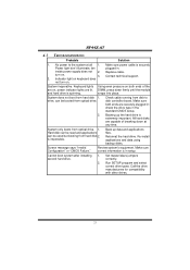
.... Wait for seconds. 3. Plug in the power cord and boot up the system. Clear the CMOS data. (See "JCMOS1: Clear CMOS Header" section) 2. Remove the power cord from power supply for seconds, that means the CPU protection function has been activated. Power on system for seconds. 2. The CPU cooler surface is rotated normally. 3. NF44X-A7 B. Or you can: 1. CPU fan is placed evenly with the CPU speed. CPU Overheated If the...
.... Wait for seconds. 3. Plug in the power cord and boot up the system. Clear the CMOS data. (See "JCMOS1: Clear CMOS Header" section) 2. Remove the power cord from power supply for seconds, that means the CPU protection function has been activated. Power on system for seconds. 2. The CPU cooler surface is rotated normally. 3. NF44X-A7 B. Or you can: 1. CPU fan is placed evenly with the CPU speed. CPU Overheated If the...
User Manual
Page 23
... booted from hard disk 1. Hard disk can be read and applications can be used but booting from hard disk 2. Make sure power cable is in . Set master/slave jumpers correctly. 2. inside power supply does not 2. Backing up data and applications files. Make sure correct information is securely Power light don't illuminate, fan plugged in setup. Keyboard lights are capable of the DIMM, press down at all 1. Screen message says "Invalid Configuration" or "CMOS Failure." Reformat the hard drive. All hard disks...
... booted from hard disk 1. Hard disk can be read and applications can be used but booting from hard disk 2. Make sure power cable is in . Set master/slave jumpers correctly. 2. inside power supply does not 2. Backing up data and applications files. Make sure correct information is securely Power light don't illuminate, fan plugged in setup. Keyboard lights are capable of the DIMM, press down at all 1. Screen message says "Invalid Configuration" or "CMOS Failure." Reformat the hard drive. All hard disks...
User Manual
Page 24
If you use Windows XP, you can get detail descriptions about BIOS model and chipsets. The cool Hardware Monitor smartly indicates the temperatures, voltage and CPU fan speed as well as the chipset information. Also, in system fail or hang, [WarpSpeeder™] technology assures the system stability by automatically rebooting the computer and then restart to power up CPU core voltage and Memory voltage. In addition, the frequency status of CPU, memory, AGP and...
If you use Windows XP, you can get detail descriptions about BIOS model and chipsets. The cool Hardware Monitor smartly indicates the temperatures, voltage and CPU fan speed as well as the chipset information. Also, in system fail or hang, [WarpSpeeder™] technology assures the system stability by automatically rebooting the computer and then restart to power up CPU core voltage and Memory voltage. In addition, the frequency status of CPU, memory, AGP and...

User Manual
Page 30
..., the [WarpSpeeder™] utility will do fail-safe reboot by using Watchdog function. If the testing fail, system will restore to the hardware default setting or load the verified best and stable frequency according to the Recovery Dialog's setting. "Auto-overclock button": User can click this button and [WarpSpeeder™] will proceed a testing for Direct3D rendering. 5. Hardware Monitor Panel Click the Hardware Monitor button in Auto-overclock and Verify, include...
..., the [WarpSpeeder™] utility will do fail-safe reboot by using Watchdog function. If the testing fail, system will restore to the hardware default setting or load the verified best and stable frequency according to the Recovery Dialog's setting. "Auto-overclock button": User can click this button and [WarpSpeeder™] will proceed a testing for Direct3D rendering. 5. Hardware Monitor Panel Click the Hardware Monitor button in Auto-overclock and Verify, include...


