

M7VKH user's manual
Page 3
... 1-2 1.1.1 Hardware 1-2 1.1.2 Software 1-5 1.1.3 Attachments 1-5 1.2 Motherboard Installation 1-6 1.2.1 Layout of Motherboard 1-6 1.3 Motherboard Quick Reference 1-7 1.3.1 Front Panel Headers (JPANEL1 / JPANEL2 1-8 1.3.2 Floppy Disk Connector (FDD1 1-10 1.3.3 Hard Disk Connectors (IDE1/IDE2 1-10 1.3.4 ATX 20-pin Power Connector (JATXPWR1 1-11 1.4 ...
... 1-2 1.1.1 Hardware 1-2 1.1.2 Software 1-5 1.1.3 Attachments 1-5 1.2 Motherboard Installation 1-6 1.2.1 Layout of Motherboard 1-6 1.3 Motherboard Quick Reference 1-7 1.3.1 Front Panel Headers (JPANEL1 / JPANEL2 1-8 1.3.2 Floppy Disk Connector (FDD1 1-10 1.3.3 Hard Disk Connectors (IDE1/IDE2 1-10 1.3.4 ATX 20-pin Power Connector (JATXPWR1 1-11 1.4 ...
M7VKH user's manual
Page 6
... Local Bus, and AGP Bus to support upgrades to find relevant topics. This manual also explains how to install the mainboard for this product! Chapter 1 Motherboard Description Introduction System Overview Thanks for multi-tasking and fully supports MS-DOS, Windows NT, Windows 2000, Novell, Windows95/98, Windows ME, UNIX, SCO UNIX...
... Local Bus, and AGP Bus to support upgrades to find relevant topics. This manual also explains how to install the mainboard for this product! Chapter 1 Motherboard Description Introduction System Overview Thanks for multi-tasking and fully supports MS-DOS, Windows NT, Windows 2000, Novell, Windows95/98, Windows ME, UNIX, SCO UNIX...
M7VKH user's manual
Page 7
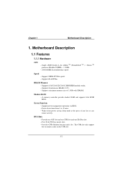
Motherboard Description 1.1 Features 1.1.1 Hardware CPU − Single AMD Socket-A for Athlon TM (Thunderbird TM ) / Duron TM processor Module-500MHz ~ 1.3GHz. − 200/266MHz System Interface speed. ... and one CNR slot and one ISA Bus slot. − Five 32-bit PCI bus master slots. − Provides CNR (Modem function only) slot . Chapter 1 Motherboard Description 1. DRAM Memory − Supports 8/16/32/64/128/256/512MB DIMM module socket. − Supports Synchronous DRAM (3.3V). − Support a maximum memory size of...
Motherboard Description 1.1 Features 1.1.1 Hardware CPU − Single AMD Socket-A for Athlon TM (Thunderbird TM ) / Duron TM processor Module-500MHz ~ 1.3GHz. − 200/266MHz System Interface speed. ... and one CNR slot and one ISA Bus slot. − Five 32-bit PCI bus master slots. − Provides CNR (Modem function only) slot . Chapter 1 Motherboard Description 1. DRAM Memory − Supports 8/16/32/64/128/256/512MB DIMM module socket. − Supports Synchronous DRAM (3.3V). − Support a maximum memory size of...
M7VKH user's manual
Page 8
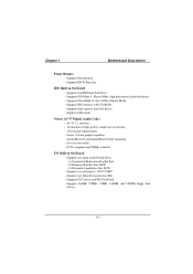
... 33/ 66/ 100 Bus Master Mode. − Supports IDE interface with CD-ROM. − Supports high capacity hard disk drives. − Supports LBA mode. Chapter 1 Motherboard Description Flash Memory − Supports flash memory. − Supports ESCD Function.
... 33/ 66/ 100 Bus Master Mode. − Supports IDE interface with CD-ROM. − Supports high capacity hard disk drives. − Supports LBA mode. Chapter 1 Motherboard Description Flash Memory − Supports flash memory. − Supports ESCD Function.
M7VKH user's manual
Page 9
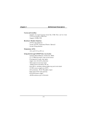
Hardware Monitor Function − CPU Fan Speed Monitor. − System and CPU Temperature Monitor (Optional). − System Voltage Monitor. Chapter 1 Motherboard Description Universal Serial Bus − Supports two back Universal Serial Bus (USB) Ports and two front Universal serial Bus (USB) Ports. − Supports 48 MHz ...
Hardware Monitor Function − CPU Fan Speed Monitor. − System and CPU Temperature Monitor (Optional). − System Voltage Monitor. Chapter 1 Motherboard Description Universal Serial Bus − Supports two back Universal Serial Bus (USB) Ports and two front Universal serial Bus (USB) Ports. − Supports 48 MHz ...
M7VKH user's manual
Page 10
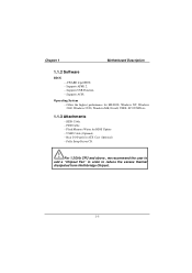
... Cable. − Flash Memory Writer for BIOS Update. − USB2 Cable (Optional). − Rear I/O Panel for ATX Case (Optional). − Fully Setup Driver CD. Chapter 1 Motherboard Description 1.1.2 Software BIOS − AWARD legal BIOS. − Supports APM1.2. − Supports USB Function. − Supports ACPI.
... Cable. − Flash Memory Writer for BIOS Update. − USB2 Cable (Optional). − Rear I/O Panel for ATX Case (Optional). − Fully Setup Driver CD. Chapter 1 Motherboard Description 1.1.2 Software BIOS − AWARD legal BIOS. − Supports APM1.2. − Supports USB Function. − Supports ACPI.

M7VKH user's manual
Page 11
Chapter 1 Motherboard Description 1.2 Motherboard Installation 1.2.1 Layout of Motherboard Model No.M7VKH 1-6
Chapter 1 Motherboard Description 1.2 Motherboard Installation 1.2.1 Layout of Motherboard Model No.M7VKH 1-6

M7VKH user's manual
Page 12
System Fan Header (JSFAN1) C. PCI BUS Slots (PCI1-5) R. ISA Slots (SL1-2) T. COM Ⅱ(JCOM2*) U. DIMMs (DIMM1-3) J. ATX Power Connector (JATXPWR1) L. Chapter 1 Motherboard Description 1.3 Motherboard Quick Reference T SR P N M L K J U I . Front Audio Header (JF_AUDIO) Q. CPU Frequency Selection (JCLK1) H. Front Panel Headers (JPANEL1-2) V. CPU Fan Header (JCFAN1) K. Wake-On-LAN Header (JWOL1) X. Telephony ...
System Fan Header (JSFAN1) C. PCI BUS Slots (PCI1-5) R. ISA Slots (SL1-2) T. COM Ⅱ(JCOM2*) U. DIMMs (DIMM1-3) J. ATX Power Connector (JATXPWR1) L. Chapter 1 Motherboard Description 1.3 Motherboard Quick Reference T SR P N M L K J U I . Front Audio Header (JF_AUDIO) Q. CPU Frequency Selection (JCLK1) H. Front Panel Headers (JPANEL1-2) V. CPU Fan Header (JCFAN1) K. Wake-On-LAN Header (JWOL1) X. Telephony ...

M7VKH user's manual
Page 13
Chapter 1 Motherboard Description 1.3.1 Front Panel Headers (JPANEL1 / JPANEL2) JPANEL1 JPANEL2 V G NC PWR-LED PWR-LED PWR 2 82 1 71 SPK HLED RST SLP NC V NC 18 17 IR ...
Chapter 1 Motherboard Description 1.3.1 Front Panel Headers (JPANEL1 / JPANEL2) JPANEL1 JPANEL2 V G NC PWR-LED PWR-LED PWR 2 82 1 71 SPK HLED RST SLP NC V NC 18 17 IR ...
M7VKH user's manual
Page 14
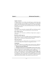
... is being read from the audio subsystem. Closing the SMI switch sends a System Management Interrupt (SMI) to a hard drive. Chapter 1 Motherboard Description Speaker Connector An offboard speaker can be installed on the front panel I/O connector supports a front panel SMI switch, which immediately goes into... servicing external interrupts (such as laptops, PDAs, and printers using the BIOS inactivity timer feature The 2-pin header located on the motherboard as a manufacturing option. To reactivate or resume the system, the SMI switch must be pressed again, or the keyboard or mouse...
... is being read from the audio subsystem. Closing the SMI switch sends a System Management Interrupt (SMI) to a hard drive. Chapter 1 Motherboard Description Speaker Connector An offboard speaker can be installed on the front panel I/O connector supports a front panel SMI switch, which immediately goes into... servicing external interrupts (such as laptops, PDAs, and printers using the BIOS inactivity timer feature The 2-pin header located on the motherboard as a manufacturing option. To reactivate or resume the system, the SMI switch must be pressed again, or the keyboard or mouse...
M7VKH user's manual
Page 15
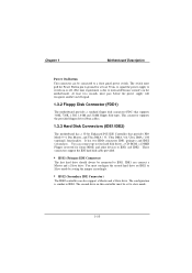
... drive should always be connected to IDE1. This connector supports the provided floppy drive ribbon cables. 1.3.3 Hard Disk Connectors (IDE1/IDE2) The motherboard has a 32-bit Enhanced PCI IDE Controller that supports 360K, 720K, 1.2M, 1.44M and 2.88M floppy disk types. IDE1 can be... is similar to IDE1. At least two seconds must be connected to internal debounce circuitry on or off signal. 1.3.2 Floppy Disk Connector (FDD1) The motherboard provides a standard floppy disk connector (FDC) that provides PIO Mode 0~4, Bus Master, and Ultra DMA / 33, Ultra DMA / 66, Ultra DMA...
... drive should always be connected to IDE1. This connector supports the provided floppy drive ribbon cables. 1.3.3 Hard Disk Connectors (IDE1/IDE2) The motherboard has a 32-bit Enhanced PCI IDE Controller that supports 360K, 720K, 1.2M, 1.44M and 2.88M floppy disk types. IDE1 can be... is similar to IDE1. At least two seconds must be connected to internal debounce circuitry on or off signal. 1.3.2 Floppy Disk Connector (FDD1) The motherboard provides a standard floppy disk connector (FDC) that provides PIO Mode 0~4, Bus Master, and Ultra DMA / 33, Ultra DMA / 66, Ultra DMA...
M7VKH user's manual
Page 16
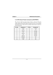
... 1.3.4 ATX 20-pin Power Connector (JATXPWR1) This connector supports the power button on this motherboard. Pin No. 1 2 3 4 5 6 7 8 9 10 Assignment +3.3V +3.3V Ground +5V Ground +5V Ground PW_OK 5V_SB +12V Pin No. 11 12 13 14 15 16 17 18 19 ...
... 1.3.4 ATX 20-pin Power Connector (JATXPWR1) This connector supports the power button on this motherboard. Pin No. 1 2 3 4 5 6 7 8 9 10 Assignment +3.3V +3.3V Ground +5V Ground +5V Ground PW_OK 5V_SB +12V Pin No. 11 12 13 14 15 16 17 18 19 ...

M7VKH user's manual
Page 17
... 3 GND Pin 4 VCC Pin 1 Mouse DATA Pin 2 NC Pin 6 NC Pin 4 VCC Pin 2 NC Pin 5 KBD Clock Pin 3 GND Pin 1 KBD DATA Keyboard 1-12 Chapter 1 Motherboard Description 1.4 Back Panel Connectors JKBMS1 PS/2 Mouse JUSB1 CN2 Parallel U14 Game Port PS/2 USB Keyboard COM1 CN1 VGA1 CN3 Speaker Line Mic out in...
... 3 GND Pin 4 VCC Pin 1 Mouse DATA Pin 2 NC Pin 6 NC Pin 4 VCC Pin 2 NC Pin 5 KBD Clock Pin 3 GND Pin 1 KBD DATA Keyboard 1-12 Chapter 1 Motherboard Description 1.4 Back Panel Connectors JKBMS1 PS/2 Mouse JUSB1 CN2 Parallel U14 Game Port PS/2 USB Keyboard COM1 CN1 VGA1 CN3 Speaker Line Mic out in...

M7VKH user's manual
Page 18
JUSB1 USB 12 34 1234 Stacked USB Connector Pin No. Assignment 1 +5 V 2 USBP0- [USBP1-] 3 USBP0+ [USBP1+] 4 Ground Signal names in brackets ([]) are for attaching USB devices such as: keyboard, mouse and other USB device. Chapter 1 Motherboard Description PS/2 Mouse / Keyboard Connectors Pin No. 1 2 3 4 5 6 Assignment Data No connection Ground +5 V Clock No connection 1.4.2 USB Connector: JUSB1 The motherboard provides a OHCI (Open Host Controller Interface) Universal Serial Bus Roots for USB Port 1. 1-13
JUSB1 USB 12 34 1234 Stacked USB Connector Pin No. Assignment 1 +5 V 2 USBP0- [USBP1-] 3 USBP0+ [USBP1+] 4 Ground Signal names in brackets ([]) are for attaching USB devices such as: keyboard, mouse and other USB device. Chapter 1 Motherboard Description PS/2 Mouse / Keyboard Connectors Pin No. 1 2 3 4 5 6 Assignment Data No connection Ground +5 V Clock No connection 1.4.2 USB Connector: JUSB1 The motherboard provides a OHCI (Open Host Controller Interface) Universal Serial Bus Roots for USB Port 1. 1-13

M7VKH user's manual
Page 19
Assignment Pin No. Assignment 1 Red 2 Green 3 Blue 4 +5V 5 Ground 6 Ground 7 Ground 8 Ground 9 +5V 10 Ground 11 +5V 12 DDC/Data 13 HSYNC 14 VSYNC 15 DDC/CLK 1-14 Your monitor will attach directly to JVGA1 connector on the motherboard. 5 1 15 11 JVGA1 Pin No. Chapter 1 Motherboard Description 1.4.3 Monitor Connector: JVGA1 This motherboard has built in video facilities.
Assignment Pin No. Assignment 1 Red 2 Green 3 Blue 4 +5V 5 Ground 6 Ground 7 Ground 8 Ground 9 +5V 10 Ground 11 +5V 12 DDC/Data 13 HSYNC 14 VSYNC 15 DDC/CLK 1-14 Your monitor will attach directly to JVGA1 connector on the motherboard. 5 1 15 11 JVGA1 Pin No. Chapter 1 Motherboard Description 1.4.3 Monitor Connector: JVGA1 This motherboard has built in video facilities.

M7VKH user's manual
Page 20
Assignment Pin No. Assignment 1 +5V 2 Ground 3 USBP2- 4 Ground 5 USBP2+ 6 USBP3+ 7 Ground 8 USBP3- 9 Ground 10 +5V 1-15 Chapter 1 Motherboard Description 1.4.4 Front USB Header: JUSB2 JUSB2 2 10 19 Pin No.
Assignment Pin No. Assignment 1 +5V 2 Ground 3 USBP2- 4 Ground 5 USBP2+ 6 USBP3+ 7 Ground 8 USBP3- 9 Ground 10 +5V 1-15 Chapter 1 Motherboard Description 1.4.4 Front USB Header: JUSB2 JUSB2 2 10 19 Pin No.

M7VKH user's manual
Page 21
... port can be accomplished by using each machine's serial port. The serial port on this chapter. If you can purchase a 9-to another computer system. Chapter 1 Motherboard Description 1.5 Serial and Parallel Interface Ports This system comes equipped with another system it can also be used to a serial port. The Serial Interface: CN1...
... port can be accomplished by using each machine's serial port. The serial port on this chapter. If you can purchase a 9-to another computer system. Chapter 1 Motherboard Description 1.5 Serial and Parallel Interface Ports This system comes equipped with another system it can also be used to a serial port. The Serial Interface: CN1...

M7VKH user's manual
Page 22
... Data Data Terminal Ready Signal Ground Data Set Ready Request to Send Clear to Send Ring Indicator DB9 PIN 1 2 3 4 5 6 7 8 9 DB25 PIN 8 3 2 20 7 6 4 5 22 1-17 Chapter 1 Motherboard Description Connectivity The serial port can be necessary to become familiar with the serial port.
... Data Data Terminal Ready Signal Ground Data Set Ready Request to Send Clear to Send Ring Indicator DB9 PIN 1 2 3 4 5 6 7 8 9 DB25 PIN 8 3 2 20 7 6 4 5 22 1-17 Chapter 1 Motherboard Description Connectivity The serial port can be necessary to become familiar with the serial port.

M7VKH user's manual
Page 23
..., a special adapter called a "Null Modem" is needed to make communication between devices, one set of serial devices that can be connected to a serial port. Chapter 1 Motherboard Description The Serial Interface Port-II: JCOM2 (Optional) 2 10 Signal DCD RX TX DTR GND DSR RTS CTS RI 1 9 Name Data Carrier Detect Receive Data...
..., a special adapter called a "Null Modem" is needed to make communication between devices, one set of serial devices that can be connected to a serial port. Chapter 1 Motherboard Description The Serial Interface Port-II: JCOM2 (Optional) 2 10 Signal DCD RX TX DTR GND DSR RTS CTS RI 1 9 Name Data Carrier Detect Receive Data...
M7VKH user's manual
Page 24
... not to another device. The jumper settings will inform you wish, two more than two ports can generally be installed on setting parameters. 1-19 Chapter 1 Motherboard Description signals to your computer is set for setting their jumper settings. Should you have installed an internal modem, be sure that accompany the peripheral...
... not to another device. The jumper settings will inform you wish, two more than two ports can generally be installed on setting parameters. 1-19 Chapter 1 Motherboard Description signals to your computer is set for setting their jumper settings. Should you have installed an internal modem, be sure that accompany the peripheral...

