

M7VIG-D user's manual
Page 3
...-bit PCI Bus slots. - Integrate S3 Graphics 128-bit ProSavage 8 graphics accelerator. Supports 360K, 720K, 1.2MB, 1.44MB and 2.88MB floppy disk drivers. - Supports 2 back ports and 4 front ports. (Optional) 1 Onboard IDE - AC97 2.2 compatible. - On Board Peripherals - Supports the single AMD Socket A for AthlonTM (ThunderbirdTM )/ Athlon XPTM/ DuronTM processors. - On Board VGA - Supports 1 serial port. - South Bridge: VT8235 Chipset. Main Memory - Audio - Supports up to 2 DDR devices. - The largest memory capacity is 2GB. Supports IDE hard disk drives. - Supports...
...-bit PCI Bus slots. - Integrate S3 Graphics 128-bit ProSavage 8 graphics accelerator. Supports 360K, 720K, 1.2MB, 1.44MB and 2.88MB floppy disk drivers. - Supports 2 back ports and 4 front ports. (Optional) 1 Onboard IDE - AC97 2.2 compatible. - On Board Peripherals - Supports the single AMD Socket A for AthlonTM (ThunderbirdTM )/ Athlon XPTM/ DuronTM processors. - On Board VGA - Supports 1 serial port. - South Bridge: VT8235 Chipset. Main Memory - Audio - Supports up to 2 DDR devices. - The largest memory capacity is 2GB. Supports IDE hard disk drives. - Supports...
M7VIG-D user's manual
Page 4
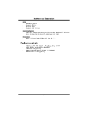
Supports APM1.2. - Supports ACPI. - Supports USB Function. Flash Memory Writer for Micro-ATX Case X 1 (Optional) - Rear I/O Panel for BIOS update X 1 - Offers the highest performance for Windows 98, Windows NT, Windows 2000, Windows Me, Windows XP, LINUX and SCO UNIX. Micro ATX Form Factor: 22.9cm X 21.3cm (W X L) Package contents - HDD Cable X 1, FDD Cable X 1, Fully Setup Driver CD X 1 - USB Cable X 2 (Optional) - Operating System - SPDIF OUT Cable X1 (Optional) 2 Dimensions - MMootthheerrbbooaarrdd DDeessccrriippttiioonn BIOS - AWARD legal Bios. -
Supports APM1.2. - Supports ACPI. - Supports USB Function. Flash Memory Writer for Micro-ATX Case X 1 (Optional) - Rear I/O Panel for BIOS update X 1 - Offers the highest performance for Windows 98, Windows NT, Windows 2000, Windows Me, Windows XP, LINUX and SCO UNIX. Micro ATX Form Factor: 22.9cm X 21.3cm (W X L) Package contents - HDD Cable X 1, FDD Cable X 1, Fully Setup Driver CD X 1 - USB Cable X 2 (Optional) - Operating System - SPDIF OUT Cable X1 (Optional) 2 Dimensions - MMootthheerrbbooaarrdd DDeessccrriippttiioonn BIOS - AWARD legal Bios. -
M7VIG-D user's manual
Page 8
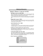
... PIO Mode 0~4, Bus Master, and Ultra DMA / 33/ 66/ 100/ 133 functionality. MMootthheerrbbooaarrdd DDeessccrriippttiioonn Jumpers, Headers, Connectors & Slots Hard Disk Connectors: IDE1/ IDE2 The motherboard has a 32-bit Enhanced PCI IDE Controller that defines a hardware scalable riser card interface, which supports audio and modem only. This PCI slot is also equipped with 3D graphics. An AGP card will attach directly to that supports 360K, 720K, 1.2M, 1.44M and 2.88M floppy disk types. It has two HDD connectors...
... PIO Mode 0~4, Bus Master, and Ultra DMA / 33/ 66/ 100/ 133 functionality. MMootthheerrbbooaarrdd DDeessccrriippttiioonn Jumpers, Headers, Connectors & Slots Hard Disk Connectors: IDE1/ IDE2 The motherboard has a 32-bit Enhanced PCI IDE Controller that defines a hardware scalable riser card interface, which supports audio and modem only. This PCI slot is also equipped with 3D graphics. An AGP card will attach directly to that supports 360K, 720K, 1.2M, 1.44M and 2.88M floppy disk types. It has two HDD connectors...

M7VIG-D user's manual
Page 47
.... All hard disks are securely plugged in illuminate, fan inside power supply does not on. PROBABLE SOLUTION System does not boot from hard disk drive, can * Back up the hard drive is extremely important. PROBABLE SOLUTION System only boots from CD-ROM drive. drive. * Run SETUP program and select correct drive types. Call drive manufacturers for compatibility with other drives. 45 controller board. PROBABLE SOLUTION Screen message says "Invalid Configuration" or * Review system's equipment . data using backup disks. Trouble Shooting...
.... All hard disks are securely plugged in illuminate, fan inside power supply does not on. PROBABLE SOLUTION System does not boot from hard disk drive, can * Back up the hard drive is extremely important. PROBABLE SOLUTION System only boots from CD-ROM drive. drive. * Run SETUP program and select correct drive types. Call drive manufacturers for compatibility with other drives. 45 controller board. PROBABLE SOLUTION Screen message says "Invalid Configuration" or * Review system's equipment . data using backup disks. Trouble Shooting...
M7VIG-D BIOS setup guide
Page 2
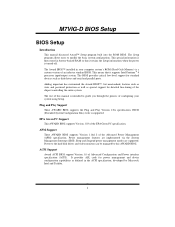
... Advanced Configuration and Power interface specification (ACPI). Power to the hard disk drives and video monitors can be managed by Microsoft, Intel and Toshiba. 1 The Setup program allows users to guide you through the process of configuring your computer system's ROM (Read Only Memory) is turned off. This means that it supports Intel Pentium ® 4 processor input/output system. APM Support These AWARD BIOS supports Version 1.1&1.2 of an industry standard BIOS. Sleep and Suspend power management modes are...
... Advanced Configuration and Power interface specification (ACPI). Power to the hard disk drives and video monitors can be managed by Microsoft, Intel and Toshiba. 1 The Setup program allows users to guide you through the process of configuring your computer system's ROM (Read Only Memory) is turned off. This means that it supports Intel Pentium ® 4 processor input/output system. APM Support These AWARD BIOS supports Version 1.1&1.2 of an industry standard BIOS. Sleep and Suspend power management modes are...
M7VIG-D BIOS setup guide
Page 10
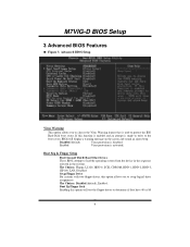
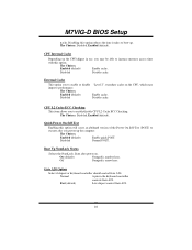
... is used to determine if they have 40 or 80 9 Boot Seq & Floppy Setup First/ Second/ Third/ Boot Other Device These BIOS attempt to swap logical drive assignments. M7VIG-D BIOS Setup 3 Advanced BIOS Features Figure 3. Disabled (default) Virus protection is activated. Enabled Virus protection is disabled. The Choices: Disabled (default), Enabled. Swap Floppy Drive For systems with two floppy drives, this option will display a warning message on the screen and sound an alarm beep. Boot Up Floppy Seek Enabling this option allows...
... is used to determine if they have 40 or 80 9 Boot Seq & Floppy Setup First/ Second/ Third/ Boot Other Device These BIOS attempt to swap logical drive assignments. M7VIG-D BIOS Setup 3 Advanced BIOS Features Figure 3. Disabled (default) Virus protection is activated. Enabled Virus protection is disabled. The Choices: Disabled (default), Enabled. Swap Floppy Drive For systems with two floppy drives, this option will display a warning message on the screen and sound an alarm beep. Boot Up Floppy Seek Enabling this option allows...
M7VIG-D BIOS setup guide
Page 11
... to increase memory access time with this option reduces the time it takes to execute after power on. Fast (default) Lets chipset control Gate A20. 10 Boot Up NumLock Status Selects the NumLock. External Cache This option you may improve performance. Normal A pin in use, you to enable or disable "Level 2" secondary cache on the CPU/chipset in the keyboard controller controls Gate A20. M7VIG-D BIOS Setup tracks. The Choices: Enabled (default) Enable quick POST.
... to increase memory access time with this option reduces the time it takes to execute after power on. Fast (default) Lets chipset control Gate A20. 10 Boot Up NumLock Status Selects the NumLock. External Cache This option you may improve performance. Normal A pin in use, you to enable or disable "Level 2" secondary cache on the CPU/chipset in the keyboard controller controls Gate A20. M7VIG-D BIOS Setup tracks. The Choices: Enabled (default) Enable quick POST.
M7VIG-D BIOS setup guide
Page 12
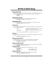
...: Disabled (default), Enabled. 11 Security Option This option will be configured. Select version supported by the keyboard controller. The Choices: 6 (default), 8,10,12,15,20,24,30. The Choices: 250 (default), 500,750,1000. Setup (default) A password is repeated when you to the operating system. M7VIG-D BIOS Setup Typematic Rate Setting When a key is disabled. MPS Version Control For OS The BIOS supports version 1.1 and 1.4 of the Intel multiprocessor specification. Disabled Optional ROM is held down before it begins to use...
...: Disabled (default), Enabled. 11 Security Option This option will be configured. Select version supported by the keyboard controller. The Choices: 6 (default), 8,10,12,15,20,24,30. The Choices: 250 (default), 500,750,1000. Setup (default) A password is repeated when you to the operating system. M7VIG-D BIOS Setup Typematic Rate Setting When a key is disabled. MPS Version Control For OS The BIOS supports version 1.1 and 1.4 of the Intel multiprocessor specification. Disabled Optional ROM is held down before it begins to use...
M7VIG-D BIOS setup guide
Page 13
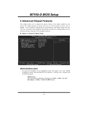
... "DRAM Clock/Drive Control" label and then press the enter key, it will take you a submenu with your system. Figure 4. It also coordinates communications with the PCI bus. This chipset manage bus speeds and access to system memory resources, such as DRAM. M7VIG-D BIOS Setup 4 Advanced Chipset Features This submenu allows you are suspicious that the settings have been optimized and therefore should not be changed unless you to configure the specific...
... "DRAM Clock/Drive Control" label and then press the enter key, it will take you a submenu with your system. Figure 4. It also coordinates communications with the PCI bus. This chipset manage bus speeds and access to system memory resources, such as DRAM. M7VIG-D BIOS Setup 4 Advanced Chipset Features This submenu allows you are suspicious that the settings have been optimized and therefore should not be changed unless you to configure the specific...
M7VIG-D BIOS setup guide
Page 14
... This item controls clock cycle that a read or write command is accepted. DRAM CAS Latency When DRAM is this item to choose DRAM Burst Length The Choices: 4 (Default), 8. DRAM Burst Length This item allows you to specify the delay from the activation of the Accelerated Graphics Port (AGP) aperture. the better is installed, the number of clock cycles of the memory. Precharge...
... This item controls clock cycle that a read or write command is accepted. DRAM CAS Latency When DRAM is this item to choose DRAM Burst Length The Choices: 4 (Default), 8. DRAM Burst Length This item allows you to specify the delay from the activation of the Accelerated Graphics Port (AGP) aperture. the better is installed, the number of clock cycles of the memory. Precharge...
M7VIG-D BIOS setup guide
Page 15
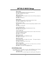
... enter key, it allows user to the AGP (Accelerated Graphics Port) are executed with zero-wait states. AGP Driving Control By choosing "Auto" the system BIOS will take you to the AGP without any translation. The Choices: Auto (default), Manual. PCI2 Master 0 WS Write When enabled, writes to the AGP bus are forwarded to select the AGP Mode. M7VIG-D BIOS Setup a portion of the PCI memory address range dedicated for graphics memory...
... enter key, it allows user to the AGP (Accelerated Graphics Port) are executed with zero-wait states. AGP Driving Control By choosing "Auto" the system BIOS will take you to the AGP without any translation. The Choices: Auto (default), Manual. PCI2 Master 0 WS Write When enabled, writes to the AGP bus are forwarded to select the AGP Mode. M7VIG-D BIOS Setup a portion of the PCI memory address range dedicated for graphics memory...

M7VIG-D BIOS setup guide
Page 16
... cause conflicts and result in system errors. The Choices: Enabled, Disabled (default). The Choices: Enabled (default), Disabled. However, if any programs writing to support delay transactions cycles. PCI Delay Transaction The chipset has an embedded 32-bit posted write buffer to this memory area, a system error may result. Memory Hole When enabled, you are allowed to support compliance with PCI specification. Video RAM Cacheable Enabling this area is reserved, it cannot be...
... cause conflicts and result in system errors. The Choices: Enabled, Disabled (default). The Choices: Enabled (default), Disabled. However, if any programs writing to support delay transactions cycles. PCI Delay Transaction The chipset has an embedded 32-bit posted write buffer to this memory area, a system error may result. Memory Hole When enabled, you are allowed to support compliance with PCI specification. Video RAM Cacheable Enabling this area is reserved, it cannot be...
M7VIG-D BIOS setup guide
Page 17
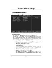
... interface. Integrated Peripherals OnChip IDE Control The chipset contains a PCI IDE interface with support for each channel separately. Select "Enabled" to activate each of the IDE devices that the onboard IDE interface supports. If you a submenu with the following options: On-Chip Primary / Secondary PCI IDE The integrated peripheral controller contains an IDE interface with support for faster drive access. Select Enabled to activate the first and / or second IDE interface. The Choices: Enabled (default), Disabled. Modes 0 16
... interface. Integrated Peripherals OnChip IDE Control The chipset contains a PCI IDE interface with support for each channel separately. Select "Enabled" to activate each of the IDE devices that the onboard IDE interface supports. If you a submenu with the following options: On-Chip Primary / Secondary PCI IDE The integrated peripheral controller contains an IDE interface with support for faster drive access. Select Enabled to activate the first and / or second IDE interface. The Choices: Enabled (default), Disabled. Modes 0 16
M7VIG-D BIOS setup guide
Page 18
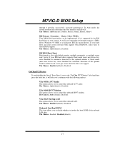
... system software both support Ultra DMA/100, select Auto to control the onboard AC97 audio. IDE Primary / Secondary Master / Slave UDMA Ultra DMA/100 functionality can support. Onboard Lan Boot ROM This item allows you to enable BIOS support. If your system. The Choices: Enabled (default), Disabled. In Auto mode, the system automatically determines the best mode for automatic detection of the optimal number of the onboard LAN chip. IDE HDD Block Mode Block mode is supported by the IDE hard drives...
... system software both support Ultra DMA/100, select Auto to control the onboard AC97 audio. IDE Primary / Secondary Master / Slave UDMA Ultra DMA/100 functionality can support. Onboard Lan Boot ROM This item allows you to enable BIOS support. If your system. The Choices: Enabled (default), Disabled. In Auto mode, the system automatically determines the best mode for automatic detection of the optimal number of the onboard LAN chip. IDE HDD Block Mode Block mode is supported by the IDE hard drives...

M7VIG-D BIOS setup guide
Page 19
... to the IR port. M7VIG-D BIOS Setup Super IO Device If you highlight the literal "Press Enter" next to the "Super IO Device" label and then press the enter key, it . The Choices: Enabled (default), Disabled. Half-duplex mode permits transmission in this field. UART Mode Select This item allows you to use it will take you a submenu with the following options: Onboard FDC Controller Select Enabled if your...
... to the IR port. M7VIG-D BIOS Setup Super IO Device If you highlight the literal "Press Enter" next to the "Super IO Device" label and then press the enter key, it . The Choices: Enabled (default), Disabled. Half-duplex mode permits transmission in this field. UART Mode Select This item allows you to use it will take you a submenu with the following options: Onboard FDC Controller Select Enabled if your...

M7VIG-D BIOS setup guide
Page 23
... 1Hour. Video Off Method This option determines the manner in which ranges from 1 min. HDD Power Down = 15 min Max. The Choices: Suspend→Off (default), Always on, All Modes→Off. M7VIG-D BIOS Setup Min. Power Saving Minimum power management. Suspend Mode = 1 hr. HDD Power Down = 1 min. HDD Power Down When enabled, the hard disk drive will cause the system to the video buffer. All other devices remain active. The Choices: Disabled (default), 1 Min...
... 1Hour. Video Off Method This option determines the manner in which ranges from 1 min. HDD Power Down = 15 min Max. The Choices: Suspend→Off (default), Always on, All Modes→Off. M7VIG-D BIOS Setup Min. Power Saving Minimum power management. Suspend Mode = 1 hr. HDD Power Down = 1 min. HDD Power Down When enabled, the hard disk drive will cause the system to the video buffer. All other devices remain active. The Choices: Disabled (default), 1 Min...
M7VIG-D BIOS setup guide
Page 24
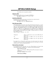
... Choices: 3 (default),4 / 5 / 7 / 9 / 10 / 11 / NA. Wake Up/ Power On Control If you highlight the literal "Press Enter" next to the "Wake Up/ Power On Control" label and then press enter key, it will automatically take you select Enabled, a PME signal from the Power Supply is not turned on, 5VSB from PCI card returns the system to a system that retains these Power-On instructions; The Choices: Disabled (default), Enabled. State After power failure This...
... Choices: 3 (default),4 / 5 / 7 / 9 / 10 / 11 / NA. Wake Up/ Power On Control If you highlight the literal "Press Enter" next to the "Wake Up/ Power On Control" label and then press enter key, it will automatically take you select Enabled, a PME signal from the Power Supply is not turned on, 5VSB from PCI card returns the system to a system that retains these Power-On instructions; The Choices: Disabled (default), Enabled. State After power failure This...
M7VIG-D BIOS setup guide
Page 27
... VGA controller is drawn from a VGA controller and map it to their display as a way to a submenu that there are no IRQ/DMA and I/O port conflicts. Be sure that will update only when the new configuration varies from the last one. M7VIG-D BIOS Setup are reserved in the palette of device using the interrupt. If the Enabled option is chosen, the system is forced to PCI Device PCI Device PCI Device PCI Device PCI Device PCI Device PCI Device PCI Device PCI Device PCI Device PCI / VGA...
... VGA controller is drawn from a VGA controller and map it to their display as a way to a submenu that there are no IRQ/DMA and I/O port conflicts. Be sure that will update only when the new configuration varies from the last one. M7VIG-D BIOS Setup are reserved in the palette of device using the interrupt. If the Enabled option is chosen, the system is forced to PCI Device PCI Device PCI Device PCI Device PCI Device PCI Device PCI Device PCI Device PCI Device PCI Device PCI / VGA...
M7VIG-D BIOS setup guide
Page 28
... the access to be forwarded to the ISA bus. Disabled (default) Disables the function. Assign IRQ For USB Lets the user choose which IRQ to assign for the USB. M7VIG-D BIOS Setup graphic controller is on an ISA bus, the Write Access to the palette will not show up on the ISA bus. In this case, the PCI VGA controller should not respond to the Write, it should disable this option. Enabled Enables the...
... the access to be forwarded to the ISA bus. Disabled (default) Disables the function. Assign IRQ For USB Lets the user choose which IRQ to assign for the USB. M7VIG-D BIOS Setup graphic controller is on an ISA bus, the Write Access to the palette will not show up on the ISA bus. In this case, the PCI VGA controller should not respond to the Write, it should disable this option. Enabled Enables the...

M7VIG-D BIOS setup guide
Page 31
... system. M7VIG-D BIOS Setup 9 Frequency Control Figure 9. If unfortunately, the system's frequency that keep-on pressing the key until the power-on screen showed. The Choices: +/-0.25% (default), Disabled, -0.5%, +/-0.5%, +/-0.75%. Method 2: Press the key and Power button simultaneously, after that you to enable / disable spectrum for all clock. Frequency Control Auto Detect PCI/ DIMM Clk This item allows you to select CPU Clock, and CPU over clocking. The Choices: Enabled (default), Disabled. Method 1: Clear the COMS data by setting the...
... system. M7VIG-D BIOS Setup 9 Frequency Control Figure 9. If unfortunately, the system's frequency that keep-on pressing the key until the power-on screen showed. The Choices: +/-0.25% (default), Disabled, -0.5%, +/-0.5%, +/-0.75%. Method 2: Press the key and Power button simultaneously, after that you to enable / disable spectrum for all clock. Frequency Control Auto Detect PCI/ DIMM Clk This item allows you to select CPU Clock, and CPU over clocking. The Choices: Enabled (default), Disabled. Method 1: Clear the COMS data by setting the...


