

M7VIF user's guide
Page 3
... 1-2 1.1 Features 1-2 1.1.1 Hardware...1-2 1.1.2 BIOS ...1-5 1.1.3 Software...1-5 1.1.4 Accessories ...1-5 1.2 Motherboard Installation 1-6 1.2.1 System Block Diagram 1-6 1.2.2 Layout of Motherboard 1-7 1.2.3 Quick Reference 1-8 1.3 CPU Installation 1-9 1.3.1 CPU Installation Procedure: Socket A 1-9 1.3.2 Frequency Selection: JCLK1 1-10 1.3.3 CPU Fan Header: JCFAN1 1-10 1.3.4 System Fan Header: JSFAN1 1-11 1.3.5 North Bridge Chipset ...
... 1-2 1.1 Features 1-2 1.1.1 Hardware...1-2 1.1.2 BIOS ...1-5 1.1.3 Software...1-5 1.1.4 Accessories ...1-5 1.2 Motherboard Installation 1-6 1.2.1 System Block Diagram 1-6 1.2.2 Layout of Motherboard 1-7 1.2.3 Quick Reference 1-8 1.3 CPU Installation 1-9 1.3.1 CPU Installation Procedure: Socket A 1-9 1.3.2 Frequency Selection: JCLK1 1-10 1.3.3 CPU Fan Header: JCFAN1 1-10 1.3.4 System Fan Header: JSFAN1 1-11 1.3.5 North Bridge Chipset ...

M7VIF user's guide
Page 6
..., Windows NT, Windows 2000, Windows ME, Windows XP, Novell, UNIX, LINUX and SCO UNIX. 1-1 In the tradition of its predecessors, this motherboard continues the commitment of your new system! M7VIF Highlights: 8 Contains on board I/O facilities, which brings to provide you the latest technology in microarchitecture design, graphics performance, system bus design, cache...
..., Windows NT, Windows 2000, Windows ME, Windows XP, Novell, UNIX, LINUX and SCO UNIX. 1-1 In the tradition of its predecessors, this motherboard continues the commitment of your new system! M7VIF Highlights: 8 Contains on board I/O facilities, which brings to provide you the latest technology in microarchitecture design, graphics performance, system bus design, cache...

M7VIF user's guide
Page 7
... (2.5 V). − Supports 6 banks up to 4Gb DRAMs for registered DDR Module (DIMMx4pcs) − 200/266/333 MHz Bus Frequency. 1-2 Chapter 1 Motherboard Description 1. Runing at 200 or 266 MHz Front Side Bus frequency. Motherboard Description 1.1 Features 1.1.1 Hardware CPU − − − Single Socket-A for unbuffered DDR SDRAM module. (DIMM x 3pcs) − Supports 8 banks...
... (2.5 V). − Supports 6 banks up to 4Gb DRAMs for registered DDR Module (DIMMx4pcs) − 200/266/333 MHz Bus Frequency. 1-2 Chapter 1 Motherboard Description 1. Runing at 200 or 266 MHz Front Side Bus frequency. Motherboard Description 1.1 Features 1.1.1 Hardware CPU − − − Single Socket-A for unbuffered DDR SDRAM module. (DIMM x 3pcs) − Supports 8 banks...
M7VIF user's guide
Page 8
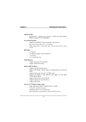
... Award BIOS™ power management functionality. − Has a power down timer from power saving sleep mode with any keyboard or mouse activity. Chapter 1 Motherboard Description Shadow RAM − Motherboard is equipped with a memory controller providing shadow RAM and support for audio on PC2001 systems. 1-3 BUS Slots − (1) AGP slot. − (1) CNR slot...
... Award BIOS™ power management functionality. − Has a power down timer from power saving sleep mode with any keyboard or mouse activity. Chapter 1 Motherboard Description Shadow RAM − Motherboard is equipped with a memory controller providing shadow RAM and support for audio on PC2001 systems. 1-3 BUS Slots − (1) AGP slot. − (1) CNR slot...

M7VIF user's guide
Page 9
.... − System Temperature. I/O facilities − One multi-mode Parallel Port capable of supporting the following specifications: Standard & Bidirection Parallel Port. Enhanced Parallel Port (EPP). Chapter 1 Motherboard Description − 18-bit stereo full-duplex CODEC with independent and variable sampling rate. − 3D Stereo Enhancement. Universal Serial Bus V2.0 − Supports two...
.... − System Temperature. I/O facilities − One multi-mode Parallel Port capable of supporting the following specifications: Standard & Bidirection Parallel Port. Enhanced Parallel Port (EPP). Chapter 1 Motherboard Description − 18-bit stereo full-duplex CODEC with independent and variable sampling rate. − 3D Stereo Enhancement. Universal Serial Bus V2.0 − Supports two...
M7VIF user's guide
Page 10
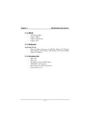
Chapter 1 Motherboard Description 1.1.2 BIOS − AWARD legal BIOS. − Supports APM1.2. − Supports USB Function. − Supports ACPI. 1.1.3 Software Operating System − Offers the highest performance for MS-DOS, Windows NT, Windows 2000, Windows 95/98, Windows ME, Windows XP, Novell, LINUX, UNIX, SCO UNIX etc. 1.1.4 Accessories − HDD Cable. − FDD Cable. − Flash Memory Writer for BIOS Update. − USB2/USB3 Cable (Optional). − Rear I/O Panel for ATX Case (Optional). − Fully Setup Driver CD. 1-5
Chapter 1 Motherboard Description 1.1.2 BIOS − AWARD legal BIOS. − Supports APM1.2. − Supports USB Function. − Supports ACPI. 1.1.3 Software Operating System − Offers the highest performance for MS-DOS, Windows NT, Windows 2000, Windows 95/98, Windows ME, Windows XP, Novell, LINUX, UNIX, SCO UNIX etc. 1.1.4 Accessories − HDD Cable. − FDD Cable. − Flash Memory Writer for BIOS Update. − USB2/USB3 Cable (Optional). − Rear I/O Panel for ATX Case (Optional). − Fully Setup Driver CD. 1-5

M7VIF user's guide
Page 11
... 1 Motherboard Description 1.2 Motherboard Installation 1.2.1 System Block Diagram PCI CONN PCI CONN PCI CONN PCI CONN PCI CONN I DE I DE USB USB CNR SLOT ACR SLOT AC' 97 CODEC HOST BUS AMD K7 PR O CE SS OR HOST BUS AGP VIA VT8367 CNTL ADDR M E M O RY 4 DDR DIMM DATA VT8233A PCI BUS 4 USB CONN. M7VIF...
... 1 Motherboard Description 1.2 Motherboard Installation 1.2.1 System Block Diagram PCI CONN PCI CONN PCI CONN PCI CONN PCI CONN I DE I DE USB USB CNR SLOT ACR SLOT AC' 97 CODEC HOST BUS AMD K7 PR O CE SS OR HOST BUS AGP VIA VT8367 CNTL ADDR M E M O RY 4 DDR DIMM DATA VT8233A PCI BUS 4 USB CONN. M7VIF...

M7VIF user's guide
Page 12
Chapter 1 Motherboard Description 1.2.2 Layout of Motherboard Model No.M7VIF 1 JKBV1 1 JCOM1 JUSBV1 CPU1 Socket A CPU DIMM1 DIMM2 DIMM3 DIMM4 JPRNT1 JCOM2 J8 U2 VT8367 JATXP WR1 2 10 1 9 ALC201A 1 1 1 JTAD1 BIOS 1 AGP SLOT PCI1 PCI ...
Chapter 1 Motherboard Description 1.2.2 Layout of Motherboard Model No.M7VIF 1 JKBV1 1 JCOM1 JUSBV1 CPU1 Socket A CPU DIMM1 DIMM2 DIMM3 DIMM4 JPRNT1 JCOM2 J8 U2 VT8367 JATXP WR1 2 10 1 9 ALC201A 1 1 1 JTAD1 BIOS 1 AGP SLOT PCI1 PCI ...

M7VIF user's guide
Page 13
Chapter 1 Motherboard Description 1.2.3 Quick Reference G F E DC B A Winbond W836 9 7 ALC201A Z BIOS Y X H W Socket A FLOPPY DISK CONN. Back Panel Connectors B. CD Audio-In Header 1 / 2 (JCDIN 1 / 2) G. ACR Slot (ACR1) K. Front Panel ...
Chapter 1 Motherboard Description 1.2.3 Quick Reference G F E DC B A Winbond W836 9 7 ALC201A Z BIOS Y X H W Socket A FLOPPY DISK CONN. Back Panel Connectors B. CD Audio-In Header 1 / 2 (JCDIN 1 / 2) G. ACR Slot (ACR1) K. Front Panel ...
M7VIF user's guide
Page 14
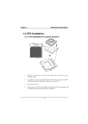
Match Pin A with the white dot/cut edge in the CPU. Press the lever down. 4. Pull the lever sideways away from the socket then raise the lever up to 90-degree angle. 2. Put the fan on the CPU by buckling it and then put the fan's powerport into the JCFAN1, then the installation will be completed. 1-9 Locate Pin A in the socket and look for the white dot or cut edge then insert the CPU. 3. Chapter 1 Motherboard Description 1.3 CPU Installation 1.3.1 CPU Installation Procedure: Socket A CPU 1.
Match Pin A with the white dot/cut edge in the CPU. Press the lever down. 4. Pull the lever sideways away from the socket then raise the lever up to 90-degree angle. 2. Put the fan on the CPU by buckling it and then put the fan's powerport into the JCFAN1, then the installation will be completed. 1-9 Locate Pin A in the socket and look for the white dot or cut edge then insert the CPU. 3. Chapter 1 Motherboard Description 1.3 CPU Installation 1.3.1 CPU Installation Procedure: Socket A CPU 1.

M7VIF user's guide
Page 15
SECONDARY IDE CONN. Chapter 1 Socket A CPU Motherboard Description DIMM1 DIMM2 DIMM3 DIMM4 1 ALC 2 0 1A VT8367 BAT1 PRIMARY IDE CONN. BIOS Winbond W83697 VT8233A VT6202 FLOPPY DISK CONN. 1.3.2 Frequency Selection: JCLK1 4 3 2 1 J S FA N 1 1 CPU Clock 100.0MHz 133.3MHz PIN 1-2 OFF ON PIN 3-4 OFF ON 1.3.3 CPU Fan Header: JCFAN1 Pin No. 1 2 3 Assignment Ground +12V Sense 1-10
SECONDARY IDE CONN. Chapter 1 Socket A CPU Motherboard Description DIMM1 DIMM2 DIMM3 DIMM4 1 ALC 2 0 1A VT8367 BAT1 PRIMARY IDE CONN. BIOS Winbond W83697 VT8233A VT6202 FLOPPY DISK CONN. 1.3.2 Frequency Selection: JCLK1 4 3 2 1 J S FA N 1 1 CPU Clock 100.0MHz 133.3MHz PIN 1-2 OFF ON PIN 3-4 OFF ON 1.3.3 CPU Fan Header: JCFAN1 Pin No. 1 2 3 Assignment Ground +12V Sense 1-10

M7VIF user's guide
Page 16
Chapter 1 Motherboard Description 1.3.4 System Fan Header: JSFAN1 Pin No. 1 2 3 Assignment Ground +12V Sense 1.3.5 North Bridge Chipset Fan Header: JNFAN1 Pin No. 1 2 Assignment Ground +12V 1-11
Chapter 1 Motherboard Description 1.3.4 System Fan Header: JSFAN1 Pin No. 1 2 3 Assignment Ground +12V Sense 1.3.5 North Bridge Chipset Fan Header: JNFAN1 Pin No. 1 2 Assignment Ground +12V 1-11

M7VIF user's guide
Page 17
Chapter 1 Motherboard Description 1.4 RAM Module Installation 1.4.1 DIMM DRAM Access Time: 2.5V Unbuffered/ Registered DDR SDRAM PC1600/ PC2100/ PC2700 Type required. DRAM Type : 64MB/ 128MB/ 256MB/ 512MB/ 1GB ... M 512 M 256 M 256 M 128 M 128 M 1 G 1 G 512 M 512 M 256 M 256 M 1 G 1 G 512 M 512 M Registered D IM M 4 (2 Rows) x64 256 M 128 M 64 M 512 M 256 M 128 M 1 G 512 M 256 M 1 G 512 M * This M7VIF motherboard does not support with parity DIMM. *The list shown above for DRAM configuration is only for reference. 1-12
Chapter 1 Motherboard Description 1.4 RAM Module Installation 1.4.1 DIMM DRAM Access Time: 2.5V Unbuffered/ Registered DDR SDRAM PC1600/ PC2100/ PC2700 Type required. DRAM Type : 64MB/ 128MB/ 256MB/ 512MB/ 1GB ... M 512 M 256 M 256 M 128 M 128 M 1 G 1 G 512 M 512 M 256 M 256 M 1 G 1 G 512 M 512 M Registered D IM M 4 (2 Rows) x64 256 M 128 M 64 M 512 M 256 M 128 M 1 G 512 M 256 M 1 G 512 M * This M7VIF motherboard does not support with parity DIMM. *The list shown above for DRAM configuration is only for reference. 1-12

M7VIF user's guide
Page 18
Chapter 1 Motherboard Description 1.4.2 How to install a DIMM Module Single Sided DIMM Double Sided DIMM 1. Push the tabs out. The Mounting Holes and plastic tabs should fit over the edge and hold the DIMM memory modules in one direction. 2. Insert the DIMM memory modules into the socket at a 90-degree angle, and then push down vertically so that it will fit into the slot in place. 1-13 The DIMM socket has a " Plastic Safety Tab", and the DIMM memory module has an "Asymmetrical notch", so the DIMM memory module can only fit into the place. 3.
Chapter 1 Motherboard Description 1.4.2 How to install a DIMM Module Single Sided DIMM Double Sided DIMM 1. Push the tabs out. The Mounting Holes and plastic tabs should fit over the edge and hold the DIMM memory modules in one direction. 2. Insert the DIMM memory modules into the socket at a 90-degree angle, and then push down vertically so that it will fit into the slot in place. 1-13 The DIMM socket has a " Plastic Safety Tab", and the DIMM memory module has an "Asymmetrical notch", so the DIMM memory module can only fit into the place. 3.

M7VIF user's guide
Page 19
... and capabilities. SECONDARY IDE CONN. VT8233A VT6202 FLOPPY DISK CONN. 1-14 With these efficient facilities, you can increase the motherboard's capabilities by adding hardware that performs tasks that are a mean of the basic system. Socket A CPU DIMM1 DIMM2 DIMM3 DIMM4 AGP SLOT PCI SLOT A LC 2 ...01A BIOS Wi n b on d W83697 ACR SLOT CNR SLOT VT8367 BAT1 PRIMARY IDE CONN. Chapter 1 Motherboard Description 1.5 Slots The slots in this motherboard are designed to hold expansion cards and connect them to the system bus.
... and capabilities. SECONDARY IDE CONN. VT8233A VT6202 FLOPPY DISK CONN. 1-14 With these efficient facilities, you can increase the motherboard's capabilities by adding hardware that performs tasks that are a mean of the basic system. Socket A CPU DIMM1 DIMM2 DIMM3 DIMM4 AGP SLOT PCI SLOT A LC 2 ...01A BIOS Wi n b on d W83697 ACR SLOT CNR SLOT VT8367 BAT1 PRIMARY IDE CONN. Chapter 1 Motherboard Description 1.5 Slots The slots in this motherboard are designed to hold expansion cards and connect them to the system bus.

M7VIF user's guide
Page 20
..., and it defines a hardware scalable riser card interface, which supports audio and modem only. 1.5.4 PCI (Peripheral Component Interconnect) Slots This motherboard is equipped with an Accelerated Graphics Port (AGP). This PCI slot is a bus standard for PCI and ISA slots, but it is... which supports audio and modem only. 1.5.2 AGP (Accelerated Graphics Port) Slot Unlike the mouse ports, keyboard ports and printer ports, this motherboard does not have built in most parts. PCI stands for improved video efficiency and performance, especially with 3D graphics. 1.5.3 CNR (Communication Network ...
..., and it defines a hardware scalable riser card interface, which supports audio and modem only. 1.5.4 PCI (Peripheral Component Interconnect) Slots This motherboard is equipped with an Accelerated Graphics Port (AGP). This PCI slot is a bus standard for PCI and ISA slots, but it is... which supports audio and modem only. 1.5.2 AGP (Accelerated Graphics Port) Slot Unlike the mouse ports, keyboard ports and printer ports, this motherboard does not have built in most parts. PCI stands for improved video efficiency and performance, especially with 3D graphics. 1.5.3 CNR (Communication Network ...
M7VIF user's guide
Page 21
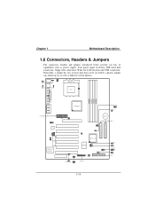
SECONDARY IDE CONN. Chapter 1 Motherboard Description 1.6 Connectors, Headers & Jumpers The connectors, headers and jumpers introduced below provide you to select a different system options. 1 JKBV1 1 JUSBV1 Socket A CPU DIMM1 DIMM2 DIMM3 ...
SECONDARY IDE CONN. Chapter 1 Motherboard Description 1.6 Connectors, Headers & Jumpers The connectors, headers and jumpers introduced below provide you to select a different system options. 1 JKBV1 1 JUSBV1 Socket A CPU DIMM1 DIMM2 DIMM3 ...

M7VIF user's guide
Page 22
... connected to the audio subsystem and does not receive output from the audio subsystem. 1-17 The speaker is not connected to the motherboard at the front panel connector. Chapter 1 Motherboard Description 1.6.1 Front Panel Connector: JPANEL1 K SLP NA POW-LED ON/OFF E IR (+) (+) (-) Y 2 24 1 23 SPK (+) (-)... Sleep Button NA POWER LED Power-on Button IrDA Connector SPK (Speaker Connector) An offboard speaker can be installed on the motherboard as a manufacturing option. The speaker (onboard or offboard) provides error beep code information during the Power On Self-Test when...
... connected to the audio subsystem and does not receive output from the audio subsystem. 1-17 The speaker is not connected to the motherboard at the front panel connector. Chapter 1 Motherboard Description 1.6.1 Front Panel Connector: JPANEL1 K SLP NA POW-LED ON/OFF E IR (+) (+) (-) Y 2 24 1 23 SPK (+) (-)... Sleep Button NA POWER LED Power-on Button IrDA Connector SPK (Speaker Connector) An offboard speaker can be installed on the motherboard as a manufacturing option. The speaker (onboard or offboard) provides error beep code information during the Power On Self-Test when...
M7VIF user's guide
Page 23
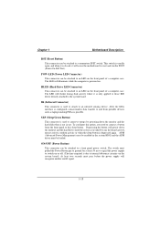
... keyboard activity, mouse activity, modem activity or when the sleep button is powered on. At least two seconds must be enabled in use. Chapter 1 Motherboard Description RST (Reset Button) This connector can be attached to an LED on the front panel of a computer case. HLED (Hard Drive LED Connector)... can be attached to the system board. The LED will recognize another on/off . (The time required is closed, it will cause the motherboard to and from the front panel to internal debounce circuitry on the system board). This switch is usually open, and when it is not in...
... keyboard activity, mouse activity, modem activity or when the sleep button is powered on. At least two seconds must be enabled in use. Chapter 1 Motherboard Description RST (Reset Button) This connector can be attached to an LED on the front panel of a computer case. HLED (Hard Drive LED Connector)... can be attached to the system board. The LED will recognize another on/off . (The time required is closed, it will cause the motherboard to and from the front panel to internal debounce circuitry on the system board). This switch is usually open, and when it is not in...
M7VIF user's guide
Page 24
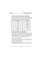
... a 120MB Floppy (reserved for VT8233A) functionality. Using the ATX power supply, function such as Soft Power Off, is supported on this motherboard. IDE1 can connect up instantly when the power connector is similar to slave mode. 1-19 Its configuration is inserted on IDE1 to IDE1 ...and IDE2. The second drive on this controller must configure the second hard drive on the board. Chapter 1 Motherboard Description 1.6.2 ATX 20-pin Power Connector: JATXPWR1 This connector supports the power button on-board. You can connect a Master and a Slave...
... a 120MB Floppy (reserved for VT8233A) functionality. Using the ATX power supply, function such as Soft Power Off, is supported on this motherboard. IDE1 can connect up instantly when the power connector is similar to slave mode. 1-19 Its configuration is inserted on IDE1 to IDE1 ...and IDE2. The second drive on this controller must configure the second hard drive on the board. Chapter 1 Motherboard Description 1.6.2 ATX 20-pin Power Connector: JATXPWR1 This connector supports the power button on-board. You can connect a Master and a Slave...

