
M7SXG user's manual
Page 3
... 1-2 1.1.1 Hardware...1-2 1.1.2 BIOS ...1-6 1.1.3 Software...1-6 1.1.4 Accessories ...1-6 1.2 Motherboard Installation 1-7 1.2.1 System Block Diagram 1-7 1.2.2 Layout of Motherboard 1-8 1.2.3 Quick Reference 1-8 1.2.3 Quick Reference 1-9 1.3 CPU Installation 1-10 1.3.1 CPU Installation Procedure: Socket 478 1-10 1.3.2 CPU Fan Header: JCFAN1 1-11 1.3.3 System Fan Header: JSFAN1 (Optional 1-11 1.4 RAM ...
... 1-2 1.1.1 Hardware...1-2 1.1.2 BIOS ...1-6 1.1.3 Software...1-6 1.1.4 Accessories ...1-6 1.2 Motherboard Installation 1-7 1.2.1 System Block Diagram 1-7 1.2.2 Layout of Motherboard 1-8 1.2.3 Quick Reference 1-8 1.2.3 Quick Reference 1-9 1.3 CPU Installation 1-10 1.3.1 CPU Installation Procedure: Socket 478 1-10 1.3.2 CPU Fan Header: JCFAN1 1-11 1.3.3 System Fan Header: JSFAN1 (Optional 1-11 1.4 RAM ...

M7SXG user's manual
Page 6
M7SXG Highlights: 8 Contains on board I/O facilities, which brings to provide you the latest technology in data processing. This motherboard is designed to take advantage of the latest industry technology to you with the ultimate solution in ...design, graphics performance, system bus design, cache architecture and much more. 8 Complies with industry software and hardware standards. Chapter 1 Motherboard Description Introduction System Overview Congratulations on board IDE facilities for full compliance and compatibility with PC Micro ATX form factor specifications. 8 Supports...
M7SXG Highlights: 8 Contains on board I/O facilities, which brings to provide you the latest technology in data processing. This motherboard is designed to take advantage of the latest industry technology to you with the ultimate solution in ...design, graphics performance, system bus design, cache architecture and much more. 8 Complies with industry software and hardware standards. Chapter 1 Motherboard Description Introduction System Overview Congratulations on board IDE facilities for full compliance and compatibility with PC Micro ATX form factor specifications. 8 Supports...

M7SXG user's manual
Page 7
... to 2.2 GHz CPU core speeds. Chipset − SiS 650/645, SiS 961. − Winbond W83697HF. Motherboard Description 1.1 Features 1.1.1 Hardware CPU − − Provides Socket-478. Chapter 1 Motherboard Description 1. The 33MHz 32 bit PCI 2.2 compliant. DRAM Memory − Supports 200MHz, 266MHz or 333MHz(only.../PC2700(only for SiS 645). − The largest memory capacity is 2 GB for unbuffer DIMMs. Shadow RAM − Motherboard is equipped with a memory controller providing shadow RAM and support for high-end workstations system. Speed Runing at 400 MHz Front Side...
... to 2.2 GHz CPU core speeds. Chipset − SiS 650/645, SiS 961. − Winbond W83697HF. Motherboard Description 1.1 Features 1.1.1 Hardware CPU − − Provides Socket-478. Chapter 1 Motherboard Description 1. The 33MHz 32 bit PCI 2.2 compliant. DRAM Memory − Supports 200MHz, 266MHz or 333MHz(only.../PC2700(only for SiS 645). − The largest memory capacity is 2 GB for unbuffer DIMMs. Shadow RAM − Motherboard is equipped with a memory controller providing shadow RAM and support for high-end workstations system. Speed Runing at 400 MHz Front Side...

M7SXG user's manual
Page 8
AC'97 Sound Codec Onboard − AC-LINK protocol compliance. − Compliant with any keyboard or mouse activity. Chapter 1 Motherboard Description Green Functionality − Supports Award BIOS ™ power management functionality. − Has a power down timer from power saving sleep mode with AC'97 2.2 specification. &#...
AC'97 Sound Codec Onboard − AC-LINK protocol compliance. − Compliant with any keyboard or mouse activity. Chapter 1 Motherboard Description Green Functionality − Supports Award BIOS ™ power management functionality. − Has a power down timer from power saving sleep mode with AC'97 2.2 specification. &#...

M7SXG user's manual
Page 9
... Ports (optional). − Supports 48 MHz USB. 1-4 Built-in a high performance 256-bit 3D engine. Support VCD, DVD and HDTV (all ATSC modes) decoding. Chapter 1 Motherboard Description Onboard Graphic − High Performance and High Quality 3D Accelerator: Built-in a high quality 3D engine. − High Performance 2D Accelerator. − MPEG-2/1 Video...
... Ports (optional). − Supports 48 MHz USB. 1-4 Built-in a high performance 256-bit 3D engine. Support VCD, DVD and HDTV (all ATSC modes) decoding. Chapter 1 Motherboard Description Onboard Graphic − High Performance and High Quality 3D Accelerator: Built-in a high quality 3D engine. − High Performance 2D Accelerator. − MPEG-2/1 Video...

M7SXG user's manual
Page 10
Dimensions (Micro ATX form-factor) − 24.5cm x 24.5cm (WxL) 1-5 Chapter 1 Motherboard Description BIOS Hardware Monitor Function − Monitors CPU Fan Speed. − Monitors System Fan Speed. − Monitors System Voltage.
Dimensions (Micro ATX form-factor) − 24.5cm x 24.5cm (WxL) 1-5 Chapter 1 Motherboard Description BIOS Hardware Monitor Function − Monitors CPU Fan Speed. − Monitors System Fan Speed. − Monitors System Voltage.

M7SXG user's manual
Page 11
Chapter 1 Motherboard Description 1.1.2 BIOS − Award BIOS. − Supports APM1.2. − Supports USB Function. − Supports ACPI. − BIOS Update. 1.1.3 Software Operating System − Offers the highest performance for MS-DOS, Windows NT, Windows 2000, Windows 95/98, Windows ME, Windows XP, Novell, SCO UNIX etc. 1.1.4 Accessories − HDD Cable. − FDD Cable. − Flash Memory Writer for BIOS Update. − JUSB1/JUSB2 Cable (Optional). − Rear I/O Panel for Micro ATX Case (Optional). − Fully Setup Driver CD. 1-6
Chapter 1 Motherboard Description 1.1.2 BIOS − Award BIOS. − Supports APM1.2. − Supports USB Function. − Supports ACPI. − BIOS Update. 1.1.3 Software Operating System − Offers the highest performance for MS-DOS, Windows NT, Windows 2000, Windows 95/98, Windows ME, Windows XP, Novell, SCO UNIX etc. 1.1.4 Accessories − HDD Cable. − FDD Cable. − Flash Memory Writer for BIOS Update. − JUSB1/JUSB2 Cable (Optional). − Rear I/O Panel for Micro ATX Case (Optional). − Fully Setup Driver CD. 1-6

M7SXG user's manual
Page 12
Chapter 1 Motherboard Description 1.2 Motherboard Installation 1.2.1 System Block Diagram SOCKET-478 Support Dual Monitor VGA V-DIMM SLOT VGA Slot VGA Connector VGA Connector Host Bus SiS650 VGA SSTL-2 Termination DDR ... 2 USB 4 USB 5 FAN FAN 12 Legacy ROM FAN CONTROL FAN CONTROL LPC Super I/O VOLTAGE MONITOR TEMPERATURE MONITOR GPIOs IR/CIR GAME/MIDI SERIAL PARALLEL FLOPPY M7SXG ATX(FSB: 400MHz) SUPPORTS 2 DIMMS SUPPORTS 1 AGP SLOT SUPPORTS 3 PCI SLOTS SUPPORTS 1 CNR SLOT SUPPORTS TELEPHONY 1-7
Chapter 1 Motherboard Description 1.2 Motherboard Installation 1.2.1 System Block Diagram SOCKET-478 Support Dual Monitor VGA V-DIMM SLOT VGA Slot VGA Connector VGA Connector Host Bus SiS650 VGA SSTL-2 Termination DDR ... 2 USB 4 USB 5 FAN FAN 12 Legacy ROM FAN CONTROL FAN CONTROL LPC Super I/O VOLTAGE MONITOR TEMPERATURE MONITOR GPIOs IR/CIR GAME/MIDI SERIAL PARALLEL FLOPPY M7SXG ATX(FSB: 400MHz) SUPPORTS 2 DIMMS SUPPORTS 1 AGP SLOT SUPPORTS 3 PCI SLOTS SUPPORTS 1 CNR SLOT SUPPORTS TELEPHONY 1-7
M7SXG user's manual
Page 13
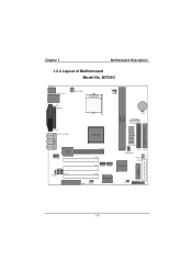
M7SXG JKBMS1 JATXPWR2 Socket 478 JCFAN1 JCOM1 JPRNT1 BAT1 JAUXPWR1 DDR 1 DDR 2 SECONDARY IDE CONN. PCI3 1 CNR1 JWOL1 Winbond I/O 1 JPANEL1 JCMOS1 2 1 1-8 PRIMARY IDE CONN. JVGA1 SP-OUT JAUD_GAME1 GAME Port LINE-IN MIC-IN 2 1 JAUDIO1 LAN CHIP JCDIN1 11 1 JCDIN2 JTAD1 AGP1 PCI1 2 2 1 1 PCI2 JUSB2 JUSB1 JATXPWR1 1 DDR1 DDR2 JDIMMPWR1 IDE2 IDE1 1 JSFAN1 FDD1 SiS 961 BIOS FLOPPY DISK CONN. Chapter 1 Motherboard Description 1.2.2 Layout of Motherboard Model No.
M7SXG JKBMS1 JATXPWR2 Socket 478 JCFAN1 JCOM1 JPRNT1 BAT1 JAUXPWR1 DDR 1 DDR 2 SECONDARY IDE CONN. PCI3 1 CNR1 JWOL1 Winbond I/O 1 JPANEL1 JCMOS1 2 1 1-8 PRIMARY IDE CONN. JVGA1 SP-OUT JAUD_GAME1 GAME Port LINE-IN MIC-IN 2 1 JAUDIO1 LAN CHIP JCDIN1 11 1 JCDIN2 JTAD1 AGP1 PCI1 2 2 1 1 PCI2 JUSB2 JUSB1 JATXPWR1 1 DDR1 DDR2 JDIMMPWR1 IDE2 IDE1 1 JSFAN1 FDD1 SiS 961 BIOS FLOPPY DISK CONN. Chapter 1 Motherboard Description 1.2.2 Layout of Motherboard Model No.

M7SXG user's manual
Page 14
...) N. PCI BUS Slots (PCI1-3) D. PRIMARY IDE CONN. Wake-On-LAN Header (JWOL1) I /O J T SiS 961 K DDR 1 DDR 2 S R Q L BIOS SECONDARY IDE CONN. AUX Power Connector (*JAUXPWR1) R. Chapter 1 Motherboard Description 1.2.3 Quick Reference FEDC B A G LAN CHIP V U Socket 478 H I Wi n bon d I . Back Panel I/O Connectors B. Front Panel Connector (JPANEL1) P M.
...) N. PCI BUS Slots (PCI1-3) D. PRIMARY IDE CONN. Wake-On-LAN Header (JWOL1) I /O J T SiS 961 K DDR 1 DDR 2 S R Q L BIOS SECONDARY IDE CONN. AUX Power Connector (*JAUXPWR1) R. Chapter 1 Motherboard Description 1.2.3 Quick Reference FEDC B A G LAN CHIP V U Socket 478 H I Wi n bon d I . Back Panel I/O Connectors B. Front Panel Connector (JPANEL1) P M.

M7SXG user's manual
Page 15
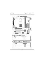
Match Pin A with the white dot/cut edge in the socket and look for the white dot or cut edge then insert the CPU. 3. Press the lever down. 4. Locate Pin A in the CPU. Chapter 1 Motherboard Description 1.3 CPU Installation 1.3.1 CPU Installation Procedure: Socket 478 CPU 1. Put the fan on the CPU by buckling it and then put the fan's power port into the JCFAN1, then the installation will be completed. 1-10 Pull the lever sideways away from the socket then raise the lever up to a 90-degree angle. 2.
Match Pin A with the white dot/cut edge in the socket and look for the white dot or cut edge then insert the CPU. 3. Press the lever down. 4. Locate Pin A in the CPU. Chapter 1 Motherboard Description 1.3 CPU Installation 1.3.1 CPU Installation Procedure: Socket 478 CPU 1. Put the fan on the CPU by buckling it and then put the fan's power port into the JCFAN1, then the installation will be completed. 1-10 Pull the lever sideways away from the socket then raise the lever up to a 90-degree angle. 2.
M7SXG user's manual
Page 16
Winbond I/O 1.3.2 CPU Fan Header: JCFAN1 Pin No. 1 2 3 Assignment Ground +12V Sense 1.3.3 System Fan Header: JSFAN1 (Optional) Pin No. 1 2 3 Assignment Ground +12V Sense 1-11 Chapter 1 Motherboard Description CPU Installation Layout Socket 478 1 JCFAN1 DDR 1 DDR 2 SECONDARY IDE CONN. PRIMARY IDE CONN. LAN CHIP 1 SiS 961 JSFAN1 BIOS FLOPPY DISK CONN.
Winbond I/O 1.3.2 CPU Fan Header: JCFAN1 Pin No. 1 2 3 Assignment Ground +12V Sense 1.3.3 System Fan Header: JSFAN1 (Optional) Pin No. 1 2 3 Assignment Ground +12V Sense 1-11 Chapter 1 Motherboard Description CPU Installation Layout Socket 478 1 JCFAN1 DDR 1 DDR 2 SECONDARY IDE CONN. PRIMARY IDE CONN. LAN CHIP 1 SiS 961 JSFAN1 BIOS FLOPPY DISK CONN.

M7SXG user's manual
Page 17
... M 1028 M 1G 128 M 256 M 512 M 256 M 512 M 512 M 512 M 1512 M 1128 M 1256 M 1G 128 M 256 M 512 M 1G 1G 1512 M 512 M 1G 2 G 1G 1G 1-12 Chapter 1 Motherboard Description 1.4 RAM Module Installation 1.4.1 DIMM DRAM Access Time: 2.5V Unbuffered DDR SDRAM (without ECC) PC1600/ PC2100/ PC2700 Type required.
... M 1028 M 1G 128 M 256 M 512 M 256 M 512 M 512 M 512 M 1512 M 1128 M 1256 M 1G 128 M 256 M 512 M 1G 1G 1512 M 512 M 1G 2 G 1G 1G 1-12 Chapter 1 Motherboard Description 1.4 RAM Module Installation 1.4.1 DIMM DRAM Access Time: 2.5V Unbuffered DDR SDRAM (without ECC) PC1600/ PC2100/ PC2700 Type required.

M7SXG user's manual
Page 18
Push the tabs out. Insert the DIMM memory modules into the socket at a 90-degree angle, then push down vertically so that it will fit into the slot in place. 1-13 The Mounting Holes and plastic tabs should fit over the edge and hold the DIMM memory modules in one direction. 2. Chapter 1 Motherboard Description 1.4.2 How to install a DIMM Module Single Sided DIMM Double Sided DIMM 1. The DIMM socket has a " Plastic Safety Tab" ,and the DIMM memory module has an Asymmetrical notch", so the DIMM memory module can only fit into the place. 3.
Push the tabs out. Insert the DIMM memory modules into the socket at a 90-degree angle, then push down vertically so that it will fit into the slot in place. 1-13 The Mounting Holes and plastic tabs should fit over the edge and hold the DIMM memory modules in one direction. 2. Chapter 1 Motherboard Description 1.4.2 How to install a DIMM Module Single Sided DIMM Double Sided DIMM 1. The DIMM socket has a " Plastic Safety Tab" ,and the DIMM memory module has an Asymmetrical notch", so the DIMM memory module can only fit into the place. 3.

M7SXG user's manual
Page 19
Expansion slots are not part of adding or enhancing the motherboard's features and capabilities. PRIMARY IDE CONN. AGP Slot LAN CHIP PCI Slot CNR Slot SiS 961 Winbond I/O 1-14 With these efficient facilities, you can increase the motherboard's capabilities by adding hardware that performs tasks that are a means of the basic system. BIOS FLOPPY DISK CONN. Socket 478 DDR 1 DDR 2 SECONDARY IDE CONN. Chapter 1 Motherboard Description 1.5 Slots The slots in this motherboard are designed to hold expansion cards and connect them to the system bus.
Expansion slots are not part of adding or enhancing the motherboard's features and capabilities. PRIMARY IDE CONN. AGP Slot LAN CHIP PCI Slot CNR Slot SiS 961 Winbond I/O 1-14 With these efficient facilities, you can increase the motherboard's capabilities by adding hardware that performs tasks that are a means of the basic system. BIOS FLOPPY DISK CONN. Socket 478 DDR 1 DDR 2 SECONDARY IDE CONN. Chapter 1 Motherboard Description 1.5 Slots The slots in this motherboard are designed to hold expansion cards and connect them to the system bus.

M7SXG user's manual
Page 20
... 1.5.1 AGP (Accelerated Graphics Port) Slot Unlike the mouse ports, keyboard ports and printer ports, this motherboard has built in video facilities and one of AGP technology for improved video efficiency and performance, especially with 3D graphics. 1.5.2 ... scalable riser card interface, which supports audio, network and modem only. 1.5.3 PCI (Peripheral Component Interconnect) Slots This motherboard is equipped with an Accelerated Graphics Port (AGP). This motherboard supports video cards for PCI slot, but it is also equipped with 3 standard PCI slots. PCI stands for Peripheral...
... 1.5.1 AGP (Accelerated Graphics Port) Slot Unlike the mouse ports, keyboard ports and printer ports, this motherboard has built in video facilities and one of AGP technology for improved video efficiency and performance, especially with 3D graphics. 1.5.2 ... scalable riser card interface, which supports audio, network and modem only. 1.5.3 PCI (Peripheral Component Interconnect) Slots This motherboard is equipped with an Accelerated Graphics Port (AGP). This motherboard supports video cards for PCI slot, but it is also equipped with 3 standard PCI slots. PCI stands for Peripheral...

M7SXG user's manual
Page 21
Chapter 1 Motherboard Description 1.6 Connectors, Headers & Jumpers The connectors, headers and jumpers introduced below provide you to select different system options. PRIMARY IDE CONN. Noticeably, a jumper has two ...
Chapter 1 Motherboard Description 1.6 Connectors, Headers & Jumpers The connectors, headers and jumpers introduced below provide you to select different system options. PRIMARY IDE CONN. Noticeably, a jumper has two ...

M7SXG user's manual
Page 22
The speaker is not connected to the motherboard at the front panel connector. Chapter 1 Motherboard Description 1.6.1 Front Panel Connector: JPANEL1 K SLP NA POW-LED ON/OFF E IR (+) (+) (-) Y 2 24 1 23 SPK (+) (-) HLED RST NA Pin Assignment No. 1 +5V 3 NA 5 NA... Ground 24 IRRX Function Sleep Button POWER LED Power-on Button IrDA Connector SPK (Speaker Connector) An offboard speaker can be installed on the motherboard as a manufacturing option. An offboard speaker can be connected to the audio subsystem and does not receive output from the audio subsystem. 1-17...
The speaker is not connected to the motherboard at the front panel connector. Chapter 1 Motherboard Description 1.6.1 Front Panel Connector: JPANEL1 K SLP NA POW-LED ON/OFF E IR (+) (+) (-) Y 2 24 1 23 SPK (+) (-) HLED RST NA Pin Assignment No. 1 +5V 3 NA 5 NA... Ground 24 IRRX Function Sleep Button POWER LED Power-on Button IrDA Connector SPK (Speaker Connector) An offboard speaker can be installed on the motherboard as a manufacturing option. An offboard speaker can be connected to the audio subsystem and does not receive output from the audio subsystem. 1-17...
M7SXG user's manual
Page 23
...(Advanced Power Management) must pass before the power supply will flicker during disk activity. At least two seconds must be enabled in use. Chapter 1 Motherboard Description RST (Reset Button) This connector can be attached to an LED on the front panel of a computer case. The LED will recognize another...Button pin to ground for at least 50 ms to signal the power supply to switch on the system board). The LED will cause the motherboard to internal debounce circuitry on or off signal. 1-18 POW-LED (Power LED Connector) This connector can be attached to a momentary SPST ...
...(Advanced Power Management) must pass before the power supply will flicker during disk activity. At least two seconds must be enabled in use. Chapter 1 Motherboard Description RST (Reset Button) This connector can be attached to an LED on the front panel of a computer case. The LED will recognize another...Button pin to ground for at least 50 ms to signal the power supply to switch on the system board). The LED will cause the motherboard to internal debounce circuitry on or off signal. 1-18 POW-LED (Power LED Connector) This connector can be attached to a momentary SPST ...

M7SXG user's manual
Page 24
... 1.6.2 ATX 20-pin Power Connector: JATXPWR1 This connector supports the power button on this motherboard. PIN Assignment PIN Assignment 1 +3.3V 11 +3.3V 2 +3.3V 12 -12V 3 Ground 13 Ground 4 +5V 14 PS_ON 5 Ground 15 Ground 6 +5V 16 Ground 7 Ground 17 Ground 8 ...
... 1.6.2 ATX 20-pin Power Connector: JATXPWR1 This connector supports the power button on this motherboard. PIN Assignment PIN Assignment 1 +3.3V 11 +3.3V 2 +3.3V 12 -12V 3 Ground 13 Ground 4 +5V 14 PS_ON 5 Ground 15 Ground 6 +5V 16 Ground 7 Ground 17 Ground 8 ...

