

M7SXF user's manual
Page 3
... 1-2 1.1.1 Hardware...1-2 1.1.2 BIOS ...1-5 1.1.3 Software...1-5 1.1.4 Accessories ...1-5 1.2 Motherboard Installation 1-6 1.2.1 System Block Diagram 1-6 1.2.2 Layout of Motherboard 1-7 1.2.3 Quick Reference 1-8 1.3 CPU Installation 1-9 1.3.1 CPU Installation Procedure: Socket 478 1-9 1.3.2 CPU Fan Header: JCFAN1 1-10 1.3.3 System Fan Header: JSFAN1 1-10 1.4 RAM Module Installation 1-11 1.4.1 DIMM...1-11 1.4.2 ...
... 1-2 1.1.1 Hardware...1-2 1.1.2 BIOS ...1-5 1.1.3 Software...1-5 1.1.4 Accessories ...1-5 1.2 Motherboard Installation 1-6 1.2.1 System Block Diagram 1-6 1.2.2 Layout of Motherboard 1-7 1.2.3 Quick Reference 1-8 1.3 CPU Installation 1-9 1.3.1 CPU Installation Procedure: Socket 478 1-9 1.3.2 CPU Fan Header: JCFAN1 1-10 1.3.3 System Fan Header: JSFAN1 1-10 1.4 RAM Module Installation 1-11 1.4.1 DIMM...1-11 1.4.2 ...

M7SXF user's manual
Page 6
M7SXF/H Highlights: 8 Contains on board I/O facilities which brings to provide you the latest technology in data processing. In the tradition of its predecessors, this motherboard continues the commitment of reliability ,performance and strives for IDE devices such as hard disks and ...CD-ROM Drives. 8 Supports the Intel Pentium® 4 (Socket 478) processor, a leading edge processor which include two serial ports (only for M7SXF), a parallel port...
M7SXF/H Highlights: 8 Contains on board I/O facilities which brings to provide you the latest technology in data processing. In the tradition of its predecessors, this motherboard continues the commitment of reliability ,performance and strives for IDE devices such as hard disks and ...CD-ROM Drives. 8 Supports the Intel Pentium® 4 (Socket 478) processor, a leading edge processor which include two serial ports (only for M7SXF), a parallel port...

M7SXF user's manual
Page 7
...− Winbond W83697HF. The 66MHz AGP 2.0 compliant interface supports 1x, 2x and 4x data transfer mode. Shadow RAM − Motherboard is equipped with unbuffer PC2100/PC1600/PC2700 (without ECC). − The largest memory capacity is 3 GB for unbuffer DIMMs. ... 333MHz (only for M7SXF) DDR SDRAM devices. − Supports 128Mb, 256Mb ,512Mb and 1GB technologies. − Max of 3 Double-Sided DIMMs with a memory controller providing shadow RAM and support for high-end workstations and servers. Chapter 1 Motherboard Description 1. Motherboard Description 1.1 Features 1.1.1...
...− Winbond W83697HF. The 66MHz AGP 2.0 compliant interface supports 1x, 2x and 4x data transfer mode. Shadow RAM − Motherboard is equipped with unbuffer PC2100/PC1600/PC2700 (without ECC). − The largest memory capacity is 3 GB for unbuffer DIMMs. ... 333MHz (only for M7SXF) DDR SDRAM devices. − Supports 128Mb, 256Mb ,512Mb and 1GB technologies. − Max of 3 Double-Sided DIMMs with a memory controller providing shadow RAM and support for high-end workstations and servers. Chapter 1 Motherboard Description 1. Motherboard Description 1.1 Features 1.1.1...
M7SXF user's manual
Page 8
... to 15 minutes. − Wakes from power saving sleep mode with CD-ROM. − Supports high capacity hard disk drives. − Supports LBA mode. Chapter 1 Motherboard Description Green Functionality − Supports Award BIOS ™ power management functionality. − Has a power down timer from 1 to 100 MB/second. − Supports Ultra DMA...
... to 15 minutes. − Wakes from power saving sleep mode with CD-ROM. − Supports high capacity hard disk drives. − Supports LBA mode. Chapter 1 Motherboard Description Green Functionality − Supports Award BIOS ™ power management functionality. − Has a power down timer from 1 to 100 MB/second. − Supports Ultra DMA...
M7SXF user's manual
Page 9
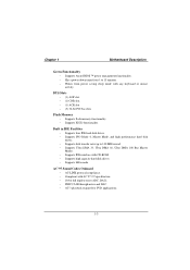
... and four front panel Universal Serial Bus Ports (optional). − Supports 48 MHz USB. Dimensions (ATX form-factor) − 24.5cm x 30.5cm (WxL) 1-4 Chapter 1 Motherboard Description I/O facilities − One multi-mode Parallel Port capable of supporting the following specifications: Standard & Bidirection Parallel Port. Normal − Supports two serial ports, 16550...
... and four front panel Universal Serial Bus Ports (optional). − Supports 48 MHz USB. Dimensions (ATX form-factor) − 24.5cm x 30.5cm (WxL) 1-4 Chapter 1 Motherboard Description I/O facilities − One multi-mode Parallel Port capable of supporting the following specifications: Standard & Bidirection Parallel Port. Normal − Supports two serial ports, 16550...

M7SXF user's manual
Page 10
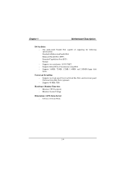
Chapter 1 Motherboard Description 1.1.2 BIOS − Phoenix legal BIOS. − Supports APM1.2. − Supports USB Function. − Supports ACPI. 1.1.3 Software Operating System − Offers the highest performance for MS-DOS, Windows NT, Windows 2000, Windows 95/98, Windows ME, Windows XP, Novell, LINUX, UNIX, SCO UNIX etc. 1.1.4 Accessories − HDD Cable. − FDD Cable. − Flash Memory Writer for BIOS Update. − JUSB1/JUSB2 Cable (Optional). − Rear I/O Panel for ATX Case (Optional). − Fully Setup Driver CD. 1-5
Chapter 1 Motherboard Description 1.1.2 BIOS − Phoenix legal BIOS. − Supports APM1.2. − Supports USB Function. − Supports ACPI. 1.1.3 Software Operating System − Offers the highest performance for MS-DOS, Windows NT, Windows 2000, Windows 95/98, Windows ME, Windows XP, Novell, LINUX, UNIX, SCO UNIX etc. 1.1.4 Accessories − HDD Cable. − FDD Cable. − Flash Memory Writer for BIOS Update. − JUSB1/JUSB2 Cable (Optional). − Rear I/O Panel for ATX Case (Optional). − Fully Setup Driver CD. 1-5

M7SXF user's manual
Page 11
Chapter 1 Motherboard Description 1.2 Motherboard Installation 1.2.1 System Block Diagram SOCKET-478 Host Bus Support Dual Monitor VGA V-DIMM SLOT VGA Slot VGA Connector VGA Connector SSTL-2 Termination DDR SDRAM (Only ... 2 USB 4 USB 5 FAN FAN 12 Legacy ROM FAN CONTROL FAN CONTROL LPC Super I/O VOLTAGE MONITOR TEMPERATURE MONITOR GPIOs IR/CIR GAME/MIDI SERIAL PARALLEL FLOPPY M7SXF/H ATX(FSB: 400MHz) SUPPORTS 3 DIMMS SUPPORTS 1 AGP SLOT SUPPORTS 5 PCI SLOTS SUPPORTS 1 ACR SLOT SUPPORTS 1 CNR SLOT SUPPORTS TELEPHONY 1-6
Chapter 1 Motherboard Description 1.2 Motherboard Installation 1.2.1 System Block Diagram SOCKET-478 Host Bus Support Dual Monitor VGA V-DIMM SLOT VGA Slot VGA Connector VGA Connector SSTL-2 Termination DDR SDRAM (Only ... 2 USB 4 USB 5 FAN FAN 12 Legacy ROM FAN CONTROL FAN CONTROL LPC Super I/O VOLTAGE MONITOR TEMPERATURE MONITOR GPIOs IR/CIR GAME/MIDI SERIAL PARALLEL FLOPPY M7SXF/H ATX(FSB: 400MHz) SUPPORTS 3 DIMMS SUPPORTS 1 AGP SLOT SUPPORTS 5 PCI SLOTS SUPPORTS 1 ACR SLOT SUPPORTS 1 CNR SLOT SUPPORTS TELEPHONY 1-6
M7SXF user's manual
Page 12
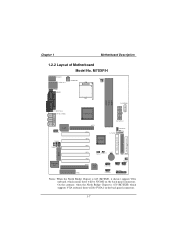
Chapter 1 Motherboard Description 1.2.2 Layout of Motherboard Model No. FLOPPY DISK CONN. SECONDARY IDE CONN. On the contrary, when the North Bridge Chipset is 645 (M7SXF), it doesn't support VGA onboard, which supports VGA onboard, there will be JVGA1 on the back panel connectors... 91 9 JUSB1 JUSB2 JPANEL1 2 1 Notes: When the North Bridge Chipset is 650 (M7SXH) which means there will be JCOM2 on the back panel connectors. 1-7 M7SXF/H JKBMS1 JCOM1 JPRNT1 J AT X PW R 2 Socket 478 J C FA N 1 DDR 1 DDR 2 DDR 3 JAUXPWR2 JCOM2/JVGA1 SP-OUT JAUD_GAME1 GAME Port ...
Chapter 1 Motherboard Description 1.2.2 Layout of Motherboard Model No. FLOPPY DISK CONN. SECONDARY IDE CONN. On the contrary, when the North Bridge Chipset is 645 (M7SXF), it doesn't support VGA onboard, which supports VGA onboard, there will be JVGA1 on the back panel connectors... 91 9 JUSB1 JUSB2 JPANEL1 2 1 Notes: When the North Bridge Chipset is 650 (M7SXH) which means there will be JCOM2 on the back panel connectors. 1-7 M7SXF/H JKBMS1 JCOM1 JPRNT1 J AT X PW R 2 Socket 478 J C FA N 1 DDR 1 DDR 2 DDR 3 JAUXPWR2 JCOM2/JVGA1 SP-OUT JAUD_GAME1 GAME Port ...

M7SXF user's manual
Page 13
Chapter 1 1.2.3 Quick Reference G F E DC B Winbond I/O BIOS H LAN Motherboard Description A Z Y Socket 478 1 1 USB 2.0 I /O Connectors ST U V O. X DDR 1 DDR 2 W DDR 3 N O PQ R A. System FAN Header (JSFAN1) C. ACR Slot (ACR1) (JDIMMPWR1) H. Clear CMOS (JCMOS1) W. ATX 12V Power Connector N. ...
Chapter 1 1.2.3 Quick Reference G F E DC B Winbond I/O BIOS H LAN Motherboard Description A Z Y Socket 478 1 1 USB 2.0 I /O Connectors ST U V O. X DDR 1 DDR 2 W DDR 3 N O PQ R A. System FAN Header (JSFAN1) C. ACR Slot (ACR1) (JDIMMPWR1) H. Clear CMOS (JCMOS1) W. ATX 12V Power Connector N. ...

M7SXF user's manual
Page 14
Pull the lever sideways away from the socket then raise the lever up to a 90-degree angle. 2. Locate Pin A in the CPU. Match Pin A with the white dot/cut edge in the socket and look for the white dot or cut edge then insert the CPU. 3. Press the lever down. 4. Chapter 1 Motherboard Description 1.3 CPU Installation 1.3.1 CPU Installation Procedure: Socket 478 CPU 1. Put the fan on the CPU by buckling it and then put the fan's power port into the JCFAN1, then the installation will be completed. 1-9
Pull the lever sideways away from the socket then raise the lever up to a 90-degree angle. 2. Locate Pin A in the CPU. Match Pin A with the white dot/cut edge in the socket and look for the white dot or cut edge then insert the CPU. 3. Press the lever down. 4. Chapter 1 Motherboard Description 1.3 CPU Installation 1.3.1 CPU Installation Procedure: Socket 478 CPU 1. Put the fan on the CPU by buckling it and then put the fan's power port into the JCFAN1, then the installation will be completed. 1-9

M7SXF user's manual
Page 15
BIOS Winbond I/O USB 2.0 1.3.2 CPU Fan Header: JCFAN1 Pin No. 1 2 3 Assignment Ground +12V Sense 1.3.3 System Fan Header: JSFAN1 Pin No. 1 2 3 Assignment Ground +12V Sense 1 JSFAN1 1-10 Chapter 1 Motherboard Description CPU Installation Layout Socket 478 1 JCFAN1 DDR 1 DDR 2 DDR 3 LAN SiS 961 PRIMARY IDE CONN. SECONDARY IDE CONN. FLOPPY DISK CONN.
BIOS Winbond I/O USB 2.0 1.3.2 CPU Fan Header: JCFAN1 Pin No. 1 2 3 Assignment Ground +12V Sense 1.3.3 System Fan Header: JSFAN1 Pin No. 1 2 3 Assignment Ground +12V Sense 1 JSFAN1 1-10 Chapter 1 Motherboard Description CPU Installation Layout Socket 478 1 JCFAN1 DDR 1 DDR 2 DDR 3 LAN SiS 961 PRIMARY IDE CONN. SECONDARY IDE CONN. FLOPPY DISK CONN.

M7SXF user's manual
Page 16
Chapter 1 Motherboard Description 1.4 RAM Module Installation 1.4.1 DIMM DRAM Access Time: 2.5V Unbuffered DDR SDRAM (without ECC) PC1600/ PC2100/ PC2700 Type required. DRAM Type: 128MB/ 256MB/ 512MB/ 1GB ...
Chapter 1 Motherboard Description 1.4 RAM Module Installation 1.4.1 DIMM DRAM Access Time: 2.5V Unbuffered DDR SDRAM (without ECC) PC1600/ PC2100/ PC2700 Type required. DRAM Type: 128MB/ 256MB/ 512MB/ 1GB ...

M7SXF user's manual
Page 17
The Mounting Holes and plastic tabs should fit over the edge and hold the DIMM memory modules in one direction. 2. Push the tabs out. Insert the DIMM memory modules into the socket at a 90-degree angle, then push down vertically so that it will fit into the slot in place. 1-12 The DIMM socket has a " Plastic Safety Tab" ,and the DIMM memory module has an Asymmetrical notch", so the DIMM memory module can only fit into the place. 3. Chapter 1 Motherboard Description 1.4.2 How to install a DIMM Module Single Sided DIMM Double Sided DIMM 1.
The Mounting Holes and plastic tabs should fit over the edge and hold the DIMM memory modules in one direction. 2. Push the tabs out. Insert the DIMM memory modules into the socket at a 90-degree angle, then push down vertically so that it will fit into the slot in place. 1-12 The DIMM socket has a " Plastic Safety Tab" ,and the DIMM memory module has an Asymmetrical notch", so the DIMM memory module can only fit into the place. 3. Chapter 1 Motherboard Description 1.4.2 How to install a DIMM Module Single Sided DIMM Double Sided DIMM 1.

M7SXF user's manual
Page 18
Chapter 1 Motherboard Description 1.5 Slots The slots in this motherboard are not part of adding or enhancing the motherboard's features and capabilities. FLOPPY DISK CONN. Socket 478 DDR 1 DDR 2 DDR 3 PRIMARY IDE CONN. Expansion slots are a means of the basic system. SECONDARY IDE CONN. AGP Slot LAN PCI Slots SiS 961 BIOS ACR Slot CNR Slot Winbond I/O USB 2.0 1-13 With these efficient facilities, you can increase the motherboard's capabilities by adding hardware that performs tasks that are designed to hold expansion cards and connect them to the system bus.
Chapter 1 Motherboard Description 1.5 Slots The slots in this motherboard are not part of adding or enhancing the motherboard's features and capabilities. FLOPPY DISK CONN. Socket 478 DDR 1 DDR 2 DDR 3 PRIMARY IDE CONN. Expansion slots are a means of the basic system. SECONDARY IDE CONN. AGP Slot LAN PCI Slots SiS 961 BIOS ACR Slot CNR Slot Winbond I/O USB 2.0 1-13 With these efficient facilities, you can increase the motherboard's capabilities by adding hardware that performs tasks that are designed to hold expansion cards and connect them to the system bus.

M7SXF user's manual
Page 19
... it is a bus standard for expansion cards, which supports audio, network and modem only. 1.5.4 PCI (Peripheral Component Interconnect) Slots This motherboard is equipped with 5 standard PCI slots. Your monitor will take advantage of the expansion slots. An AGP card will attach directly to that ... audio, network and modem only. 1.5.2 AGP (Accelerated Graphics Port) Slot Unlike the mouse ports, keyboard ports and printer ports, this motherboard does not have built in most parts. This PCI slot is also equipped with 3D graphics. 1.5.3 CNR (Communication Network Riser) Slot The...
... it is a bus standard for expansion cards, which supports audio, network and modem only. 1.5.4 PCI (Peripheral Component Interconnect) Slots This motherboard is equipped with 5 standard PCI slots. Your monitor will take advantage of the expansion slots. An AGP card will attach directly to that ... audio, network and modem only. 1.5.2 AGP (Accelerated Graphics Port) Slot Unlike the mouse ports, keyboard ports and printer ports, this motherboard does not have built in most parts. This PCI slot is also equipped with 3D graphics. 1.5.3 CNR (Communication Network Riser) Slot The...

M7SXF user's manual
Page 20
... of capabilities such as power supply, front panel signal revelation, IDE hard disk connection, floppy disk connection, Wake On LAN function and USB connection. Chapter 1 Motherboard Description 1.6 Connectors, Headers & Jumpers The connectors, headers and jumpers introduced below provide you to select different system options.
... of capabilities such as power supply, front panel signal revelation, IDE hard disk connection, floppy disk connection, Wake On LAN function and USB connection. Chapter 1 Motherboard Description 1.6 Connectors, Headers & Jumpers The connectors, headers and jumpers introduced below provide you to select different system options.

M7SXF user's manual
Page 21
The speaker is not connected to the motherboard at the front panel connector. An offboard speaker can be installed on Button IrDA Connector SPK (Speaker Connector) An offboard speaker can be connected to ... The speaker (onboard or offboard) provides error beep code information during the Power On Self-Test when the computer cannot use the video interface. Chapter 1 Motherboard Description 1.6.1 Front Panel Connector: JPANEL1 K SLP NA POW-LED ON/OFF E IR (+) (+) (-) Y 2 24 1 23 SPK (+) (-) HLED RST NA Pin Assignment No. 1 +5V 3 NA 5 NA 7 Speaker...
The speaker is not connected to the motherboard at the front panel connector. An offboard speaker can be installed on Button IrDA Connector SPK (Speaker Connector) An offboard speaker can be connected to ... The speaker (onboard or offboard) provides error beep code information during the Power On Self-Test when the computer cannot use the video interface. Chapter 1 Motherboard Description 1.6.1 Front Panel Connector: JPANEL1 K SLP NA POW-LED ON/OFF E IR (+) (+) (-) Y 2 24 1 23 SPK (+) (-) HLED RST NA Pin Assignment No. 1 +5V 3 NA 5 NA 7 Speaker...

M7SXF user's manual
Page 22
... system is invoked by any keyboard activity, mouse activity, modem activity or when the sleep button is depressed again. Depressing the button will cause the motherboard to reset and run the POST (Power On Self Test). HLED (Hard Drive LED Connector) This connector can be attached to a front panel power switch... applies to those IDE drives directly attached to the system board. After the IrDA interface is used to attach to an infrared sensing device. Chapter 1 Motherboard Description RST (Reset Button) This connector can be attached to an LED on the front panel of a computer case.
... system is invoked by any keyboard activity, mouse activity, modem activity or when the sleep button is depressed again. Depressing the button will cause the motherboard to reset and run the POST (Power On Self Test). HLED (Hard Drive LED Connector) This connector can be attached to a front panel power switch... applies to those IDE drives directly attached to the system board. After the IrDA interface is used to attach to an infrared sensing device. Chapter 1 Motherboard Description RST (Reset Button) This connector can be attached to an LED on the front panel of a computer case.

M7SXF user's manual
Page 23
... 4 Ground 1.6.4 AUX Power Connector: JAUXPWR1 PIN Assignment PIN Assignment 1 Ground 4 +3.3V 2 Ground 5 +3.3V 3 Ground 6 +5V 1-18 Chapter 1 Motherboard Description 1.6.2 ATX 20-pin Power Connector: JATXPWR1 This connector supports the power button on this motherboard. Using the ATX power supply, function such as Soft Power Off is inserted on the board. This power...
... 4 Ground 1.6.4 AUX Power Connector: JAUXPWR1 PIN Assignment PIN Assignment 1 Ground 4 +3.3V 2 Ground 5 +3.3V 3 Ground 6 +5V 1-18 Chapter 1 Motherboard Description 1.6.2 ATX 20-pin Power Connector: JATXPWR1 This connector supports the power button on this motherboard. Using the ATX power supply, function such as Soft Power Off is inserted on the board. This power...

M7SXF user's manual
Page 24
...cable provided. • IDE1 (Primary IDE Connector) The first hard drive should always be set to slave mode. 1.6.7 Floppy Disk Connector: FDD1 The motherboard provides a standard floppy disk connector (FDC) that provides PIO Mode 0~4, Bus Master, and Ultra DMA / 33, Ultra DMA / 66,Ultra DMA ...) The IDE2 controller can also support a Master and a Slave drive. The configuration is similar to IDE1 and IDE2. Chapter 1 Motherboard Description 1.6.5 AUX Power Connector: JAUXPWR2 PIN Assignment PIN Assignment 1 VCC 3 Ground 2 Ground 4 +12V 1.6.6 Hard Disk Connectors: IDE1/IDE2 The...
...cable provided. • IDE1 (Primary IDE Connector) The first hard drive should always be set to slave mode. 1.6.7 Floppy Disk Connector: FDD1 The motherboard provides a standard floppy disk connector (FDC) that provides PIO Mode 0~4, Bus Master, and Ultra DMA / 33, Ultra DMA / 66,Ultra DMA ...) The IDE2 controller can also support a Master and a Slave drive. The configuration is similar to IDE1 and IDE2. Chapter 1 Motherboard Description 1.6.5 AUX Power Connector: JAUXPWR2 PIN Assignment PIN Assignment 1 VCC 3 Ground 2 Ground 4 +12V 1.6.6 Hard Disk Connectors: IDE1/IDE2 The...

