

User Guide
Page 1
... publication, in part or in whole, is no representations or warranties with respect to the contents here without first obtaining the vendor's approval in writing. K8T80-A7 FCC Information and Copyright This equipment has been tested and found in this user's manual. The vendor makes no guarantee that interference will not be...
... publication, in part or in whole, is no representations or warranties with respect to the contents here without first obtaining the vendor's approval in writing. K8T80-A7 FCC Information and Copyright This equipment has been tested and found in this user's manual. The vendor makes no guarantee that interference will not be...

User Guide
Page 2
Table of Contents Chapter 1: 1.1 1.2 1.3 1.4 Introduction 1 Features 1 Package List 3 Layout 4 Components 5 Chapter 2: 2.1 2.2 2.3 2.4 Hardware Installation 6 Central Processing Unit (CPU 6 FAN Headers 8 Memory Module Installation 8 Connectors and Slots 9 Chapter 3: 3.1 3.2 Headers & Jumpers Setup 10 How to Setup Jumpers 10 Detail Settings 10 Chapter 4: 4.1 4.2 4.3 Useful Help 14 Award BIOS Beep Code 14 Extra Information 14 Troubleshooting 16 Chapter 5: 5.1 5.2 5.3 5.4 WarpSpeeder 17 Introduction 17 System Requirement 17 Installation 18 [WarpSpeeder™] ...
Table of Contents Chapter 1: 1.1 1.2 1.3 1.4 Introduction 1 Features 1 Package List 3 Layout 4 Components 5 Chapter 2: 2.1 2.2 2.3 2.4 Hardware Installation 6 Central Processing Unit (CPU 6 FAN Headers 8 Memory Module Installation 8 Connectors and Slots 9 Chapter 3: 3.1 3.2 Headers & Jumpers Setup 10 How to Setup Jumpers 10 Detail Settings 10 Chapter 4: 4.1 4.2 4.3 Useful Help 14 Award BIOS Beep Code 14 Extra Information 14 Troubleshooting 16 Chapter 5: 5.1 5.2 5.3 5.4 WarpSpeeder 17 Introduction 17 System Requirement 17 Installation 18 [WarpSpeeder™] ...

User Guide
Page 3
K8T80-A7 CHAPTER 1: INTRODUCTION 1.1 FEATURES A. Hardware CPU Supports Socket 754. Integrate hardware monitor functions. 10/100 LAN Chip: Realtek RTL8100C. Supports 10/100 Mb/s auto-negotiation operation. ...
K8T80-A7 CHAPTER 1: INTRODUCTION 1.1 FEATURES A. Hardware CPU Supports Socket 754. Integrate hardware monitor functions. 10/100 LAN Chip: Realtek RTL8100C. Supports 10/100 Mb/s auto-negotiation operation. ...

User Guide
Page 4
... I/O Connectors and Headers 1 front panel header supports front panel facilities. 1 CD-in connector supports 1 CD-ROM audio-in SB VT8237R. Compliant with SATA Version 1.0 specification. K8T80-A7 Slot 5 x PCI bus master slots. 1 x AGP 4x/8x compatible slot. 1 x CNR slot. Supports 2 serial ATA (SATA) ports. - Supports PIO mode 5, Bus Master, and Ultra DMA...
... I/O Connectors and Headers 1 front panel header supports front panel facilities. 1 CD-in connector supports 1 CD-ROM audio-in SB VT8237R. Compliant with SATA Version 1.0 specification. K8T80-A7 Slot 5 x PCI bus master slots. 1 x AGP 4x/8x compatible slot. 1 x CNR slot. Supports 2 serial ATA (SATA) ports. - Supports PIO mode 5, Bus Master, and Ultra DMA...

User Guide
Page 5
Software Supports 9th TouchTM, FlasherTM, WinFlasherTM, and WarpspeederTM. Supports APM1.2, ACPI, and USB functions. BIOS & Software BIOS Award legal BIOS. K8T80-A7 Back Panel I /O panel for ATX case x1 USB 2.0 cable x1 (optional) Serial ATA cable x2 (optional) S/PDIF out cable x1 (optional) 3 Offers the highest performance ...
Software Supports 9th TouchTM, FlasherTM, WinFlasherTM, and WarpspeederTM. Supports APM1.2, ACPI, and USB functions. BIOS & Software BIOS Award legal BIOS. K8T80-A7 Back Panel I /O panel for ATX case x1 USB 2.0 cable x1 (optional) Serial ATA cable x2 (optional) S/PDIF out cable x1 (optional) 3 Offers the highest performance ...
User Guide
Page 6
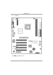
CPU1 IDE2 IDE1 2 JUSB4 1 10 2 10 JUSB3 1 1 JUSBV2 VT8237R Super I/O JSATA2 7 1 JSATA1 7 1 JCMOS1 JCI1 1 1 BAT1 JSFAN1 1 BIOS JPANEL1 2 24 1 23 4 1.3 LAYOUT JKBMS1 JKBV1 1 JATXPWR2 JATXPWR1 K8T80-A7 JCFAN1 1 JCOM2 DIMM1 DIMM2 FDD1 JPRNT1 JUSBV1 1 JUSB1 JUSBLAN1 K8T800 Pro JAUDIO1 AGP1 PCI1 LAN PCI2 JAUDIO2 2 14 1 13 1 JCDIN1 1 JSPDIF_OUT1 Codec CNR1 PCI3 PCI4 PCI5 Note: ■ represents the 1st pin.
CPU1 IDE2 IDE1 2 JUSB4 1 10 2 10 JUSB3 1 1 JUSBV2 VT8237R Super I/O JSATA2 7 1 JSATA1 7 1 JCMOS1 JCI1 1 1 BAT1 JSFAN1 1 BIOS JPANEL1 2 24 1 23 4 1.3 LAYOUT JKBMS1 JKBV1 1 JATXPWR2 JATXPWR1 K8T80-A7 JCFAN1 1 JCOM2 DIMM1 DIMM2 FDD1 JPRNT1 JUSBV1 1 JUSB1 JUSBLAN1 K8T800 Pro JAUDIO1 AGP1 PCI1 LAN PCI2 JAUDIO2 2 14 1 13 1 JCDIN1 1 JSPDIF_OUT1 Codec CNR1 PCI3 PCI4 PCI5 Note: ■ represents the 1st pin.

User Guide
Page 7
... audio-in connector. Rear side connectors (back panel). P. F. JUSB3/JUSB4: Front panel USB ports Interconnect slots. DIMM1/DIMM2: DDR memory modules. H. JATXPWR1/JATXPWR2: ATX power L. G. K8T80-A7 1.4 COMPONENTS H I GF ED C B Codec LAN A J K8T800 Pro CPU1 BAT1 BIOS Super I . S. JSPDIF_OUT1: Digital audio-out connector. AGP1: Accelerated Graphics Port slot. R. M. I /O VT8237R K L MN O PQ R S T U A. JUSBV1...
... audio-in connector. Rear side connectors (back panel). P. F. JUSB3/JUSB4: Front panel USB ports Interconnect slots. DIMM1/DIMM2: DDR memory modules. H. JATXPWR1/JATXPWR2: ATX power L. G. K8T80-A7 1.4 COMPONENTS H I GF ED C B Codec LAN A J K8T800 Pro CPU1 BAT1 BIOS Super I . S. JSPDIF_OUT1: Digital audio-out connector. AGP1: Accelerated Graphics Port slot. R. M. I /O VT8237R K L MN O PQ R S T U A. JUSBV1...

User Guide
Page 8
K8T80-A7 CHAPTER 2: HARDWARE INSTALLATION 2.1 CENTRAL PROCESSING UNIT (CPU) Step 1: Pull the lever sideways away from the socket and then raise the lever up to a 90-degree angle. Step 2: Look for the black cut edge on socket, and the white dot on CPU should point forwards this black cut edge. The CPU will fit only in the correct orientation. 6
K8T80-A7 CHAPTER 2: HARDWARE INSTALLATION 2.1 CENTRAL PROCESSING UNIT (CPU) Step 1: Pull the lever sideways away from the socket and then raise the lever up to a 90-degree angle. Step 2: Look for the black cut edge on socket, and the white dot on CPU should point forwards this black cut edge. The CPU will fit only in the correct orientation. 6

User Guide
Page 9
K8T80-A7 Step 3: Hold the CPU down firmly, and then close the lever to the JCFAN1. Step 4: Put the CPU Fan on the CPU and buckle it. This completes the installation. 7 Connect the CPU FAN power cable to complete the installation.
K8T80-A7 Step 3: Hold the CPU down firmly, and then close the lever to the JCFAN1. Step 4: Put the CPU Fan on the CPU and buckle it. This completes the installation. 7 Connect the CPU FAN power cable to complete the installation.

User Guide
Page 10
... sense Note: The JCFAN1, JSFAN1 and JNFAN1 support 3-pin head connector. Connect the fan cable to the connector while matching the black wire to pin#1. K8T80-A7 2.2 FAN HEADERS These fan headers support cooling-fans built in place and the DIMM is Ground and should be different according to GND. 2.3 1. Align a DIMM...
... sense Note: The JCFAN1, JSFAN1 and JNFAN1 support 3-pin head connector. Connect the fan cable to the connector while matching the black wire to pin#1. K8T80-A7 2.2 FAN HEADERS These fan headers support cooling-fans built in place and the DIMM is Ground and should be different according to GND. 2.3 1. Align a DIMM...

User Guide
Page 11
... first hard drive should always be connected to four hard disk drives. JSATA1/JSATA2: Serial ATA Connectors The motherboard has a PCI to that video card. K8T80-A7 2.4 CONNECTORS AND SLOTS FDD1: Floppy Disk Connector The motherboard provides a standard floppy disk connector that provides PIO Mode 0~5, Bus Master, and Ultra DMA 33/ 66...
... first hard drive should always be connected to four hard disk drives. JSATA1/JSATA2: Serial ATA Connectors The motherboard has a PCI to that video card. K8T80-A7 2.4 CONNECTORS AND SLOTS FDD1: Floppy Disk Connector The motherboard provides a standard floppy disk connector that provides PIO Mode 0~5, Bus Master, and Ultra DMA 33/ 66...

User Guide
Page 12
... 2 +12V Pin Assignment 3 Ground 4 Ground 10 JATXPWR2: By connecting this connector, it will provide +12V to set up jumpers. When the jumper cap is "open". K8T80-A7 CHAPTER 3: HEADERS & JUMPERS SETUP 3.1 HOW TO SETUP JUMPERS The illustration shows how to CPU power circuit.
... 2 +12V Pin Assignment 3 Ground 4 Ground 10 JATXPWR2: By connecting this connector, it will provide +12V to set up jumpers. When the jumper cap is "open". K8T80-A7 CHAPTER 3: HEADERS & JUMPERS SETUP 3.1 HOW TO SETUP JUMPERS The illustration shows how to CPU power circuit.
User Guide
Page 13
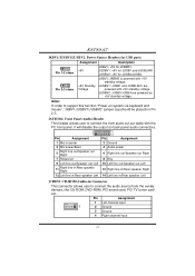
... header allows user to connect the audio source from the veriaty devices, like CD-ROM, DVD-ROM, PCI sound card, PCI TV turner card etc.. K8T80-A7 JKBV1/JUSBV1/JUSBV2: Power Source Headers for USB ports 1 Pin 1-2 close 1 Pin 2-3 close Assignment Description JKBV1: +5V for JKBMS1. +5V JUSBV1: +5V for JUSB3/JUSB4...
... header allows user to connect the audio source from the veriaty devices, like CD-ROM, DVD-ROM, PCI sound card, PCI TV turner card etc.. K8T80-A7 JKBV1/JUSBV1/JUSBV2: Power Source Headers for USB ports 1 Pin 1-2 close 1 Pin 2-3 close Assignment Description JKBV1: +5V for JKBMS1. +5V JUSBV1: +5V for JUSB3/JUSB4...
User Guide
Page 14
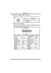
K8T80-A7 JSPDIF_OUT1: Digital Audio-out Connector This connector allows user to connect the PC case's front panel switch functions. It allows user to connect the PCI ...
K8T80-A7 JSPDIF_OUT1: Digital Audio-out Connector This connector allows user to connect the PC case's front panel switch functions. It allows user to connect the PCI ...

User Guide
Page 15
... avoid damaging the motherboard. JCI1: Chassis Open Header This connector allows system to monitor PC case open signal 2 Ground 13 Pin Assignment 1 Case open status. K8T80-A7 JCMOS1: Clear CMOS Header By placing the jumper on pin2-3, it will record to the CMOS and show the message on the AC. 6. Set the...
... avoid damaging the motherboard. JCI1: Chassis Open Header This connector allows system to monitor PC case open signal 2 Ground 13 Pin Assignment 1 Case open status. K8T80-A7 JCMOS1: Clear CMOS Header By placing the jumper on pin2-3, it will record to the CMOS and show the message on the AC. 6. Set the...

User Guide
Page 16
In this Case, please follow the procedure below to restore the BIOS: 1. Confirm motherboard model and download the respectively BIOS from the Biostar website: www.biostar.com.tw 3. Make a bootable floppy disk. 2. System will boot-up the system, it means the BIOS contents are corrupted.... will update BIOS automatically and restart. 9. K8T80-A7 CHAPTER 4: USEFUL HELP 4.1 AWARD BIOS BEEP CODE Beep Sound One long beep followed by virus, the Boot-Block function will help to restore BIOS. Download the Flash Utility "AWDFLASH.exe" from Biostar website. 4. Type "Awdflash xxxx.bf/sn...
In this Case, please follow the procedure below to restore the BIOS: 1. Confirm motherboard model and download the respectively BIOS from the Biostar website: www.biostar.com.tw 3. Make a bootable floppy disk. 2. System will boot-up the system, it means the BIOS contents are corrupted.... will update BIOS automatically and restart. 9. K8T80-A7 CHAPTER 4: USEFUL HELP 4.1 AWARD BIOS BEEP CODE Beep Sound One long beep followed by virus, the Boot-Block function will help to restore BIOS. Download the Flash Utility "AWDFLASH.exe" from Biostar website. 4. Type "Awdflash xxxx.bf/sn...

User Guide
Page 17
... with the CPU speed. Or you can: 1. The CPU cooler surface is over heated, the motherboard will shutdown automatically to relief the CPU protection function. 1. K8T80-A7 B. CPU Overheated If the system shutdown automatically after power on again. In this case, please double check: 1. Remove the power cord from power supply for...
... with the CPU speed. Or you can: 1. The CPU cooler surface is over heated, the motherboard will shutdown automatically to relief the CPU protection function. 1. K8T80-A7 B. CPU Overheated If the system shutdown automatically after power on again. In this case, please double check: 1. Remove the power cord from power supply for...

User Guide
Page 18
... are securely plugged in the standard CMOS setup. Call the drive manufacturers for compatibility with other drives. 16 inside power supply does not turn on . 3. K8T80-A7 4.3 TROUBLESHOOTING Probable Solution 1. All hard disks are lit, and hard drive is Power light don't illuminate, fan securely plugged in setup.
... are securely plugged in the standard CMOS setup. Call the drive manufacturers for compatibility with other drives. 16 inside power supply does not turn on . 3. K8T80-A7 4.3 TROUBLESHOOTING Probable Solution 1. All hard disks are lit, and hard drive is Power light don't illuminate, fan securely plugged in setup.

User Guide
Page 19
... prefer or they can get the best CPU performance with the CPU speed are synchronically shown on the other hand, helps to install DirectX 8.1.) 17 K8T80-A7 CHAPTER 5: WARPSPEEDER™ 5.1 INTRODUCTION [WarpSpeeder™], a new powerful control utility, features three user-friendly functions including Overclock Manager, Overvoltage Manager, and Hardware Monitor...
... prefer or they can get the best CPU performance with the CPU speed are synchronically shown on the other hand, helps to install DirectX 8.1.) 17 K8T80-A7 CHAPTER 5: WARPSPEEDER™ 5.1 INTRODUCTION [WarpSpeeder™], a new powerful control utility, features three user-friendly functions including Overclock Manager, Overvoltage Manager, and Hardware Monitor...

User Guide
Page 20
... utility and [WarpSpeeder™] utility will change according to install. 2. Please click "Next" button and follow the default procedure to your motherboard on hand. 18 K8T80-A7 5.3 1.
... utility and [WarpSpeeder™] utility will change according to install. 2. Please click "Next" button and follow the default procedure to your motherboard on hand. 18 K8T80-A7 5.3 1.