
K8M800-M7A user's manual
Page 1
... to provide reasonable protection against harmful interference in a residential installation. All the brand and product names are designed to Part 15 of their respective companies. K8M800-M7A FCC Information and Copyright This equipment has been tested and found in this user's manual. These limits are trademarks of the FCC Rules. There is...
... to provide reasonable protection against harmful interference in a residential installation. All the brand and product names are designed to Part 15 of their respective companies. K8M800-M7A FCC Information and Copyright This equipment has been tested and found in this user's manual. These limits are trademarks of the FCC Rules. There is...
K8M800-M7A user's manual
Page 3
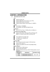
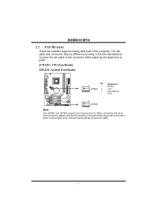
... Three 32bit PCI bus master slots. Supports PIO mode 0~4. System Memory Supports up to 2 DDR devices. Chipset North Bridge: VIA K8M800. One CNR slot. Supports Ultra DMA 33/ 66/100/133 Bus Master Mode. Supports AMD Sempron processor. On-board IDE Two on...reference.) DIMM Socket Location DIMM1 DIMM2 DDR Module Total Memory Size 128MB/256MB/512MB/1GB *1 128MB/256MB/512MB/1GB *1 Max is 2 GB. 1 K8M800-M7A CHAPTER 1: INTRODUCTION 1.1 MOTHERBOARD FEATURES CPU Supports Socket 754. Supports HyperTransport Technology up to 1600MT/s. Dimensions Micro ATX Form Factor: 18.999cm (W) x ...
... Three 32bit PCI bus master slots. Supports PIO mode 0~4. System Memory Supports up to 2 DDR devices. Chipset North Bridge: VIA K8M800. One CNR slot. Supports Ultra DMA 33/ 66/100/133 Bus Master Mode. Supports AMD Sempron processor. On-board IDE Two on...reference.) DIMM Socket Location DIMM1 DIMM2 DDR Module Total Memory Size 128MB/256MB/512MB/1GB *1 128MB/256MB/512MB/1GB *1 Max is 2 GB. 1 K8M800-M7A CHAPTER 1: INTRODUCTION 1.1 MOTHERBOARD FEATURES CPU Supports Socket 754. Supports HyperTransport Technology up to 1600MT/s. Dimensions Micro ATX Form Factor: 18.999cm (W) x ...
K8M800-M7A user's manual
Page 4
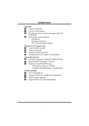
Compliant with AC'97 Version 2.3 specification. Half/Full duplex capability. Provides the most commonly used legacy Super I /O Chip: ITE IT8705AF. Support 6 channels. K8M800-M7A Super I /O functionality. Environment Control initiatives, H/W Monitor Fan Speed Controller ITE's "Smart Guardian" function Onboard AC'97 Sound Codec Chip: REALTEK ALC655. Onboard ...
Compliant with AC'97 Version 2.3 specification. Half/Full duplex capability. Provides the most commonly used legacy Super I /O Chip: ITE IT8705AF. Support 6 channels. K8M800-M7A Super I /O functionality. Environment Control initiatives, H/W Monitor Fan Speed Controller ITE's "Smart Guardian" function Onboard AC'97 Sound Codec Chip: REALTEK ALC655. Onboard ...
K8M800-M7A user's manual
Page 5
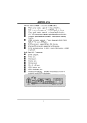
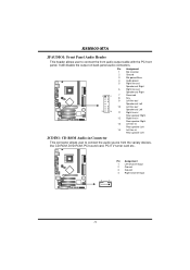
K8M800-M7A Internal On-board I/O Connectors and Headers 1 front panel header supports front panel facilities. 1 CD-in connector supports 1 CD-ROM audio-in device. 1 front audio header ...
K8M800-M7A Internal On-board I/O Connectors and Headers 1 front panel header supports front panel facilities. 1 CD-in connector supports 1 CD-ROM audio-in device. 1 front audio header ...

K8M800-M7A user's manual
Page 7
K8M800-M7A CHAPTER 2: HARDWARE INSTALLATION 2.1 INSTALLING CENTRAL PROCESSING UNIT (CPU) Step 1: Pull the lever toward direction A from the socket and then raise the lever up to a 90-...
K8M800-M7A CHAPTER 2: HARDWARE INSTALLATION 2.1 INSTALLING CENTRAL PROCESSING UNIT (CPU) Step 1: Pull the lever toward direction A from the socket and then raise the lever up to a 90-...
K8M800-M7A user's manual
Page 8
... JSFAN1: System Fan Header 13 Pin Assignment 1 Ground JCFAN1 2 +12V 3 FAN RPM rate sense 13 JSFAN1 Note: The JCFAN1 and JSFAN1 support 3-pin head connector. K8M800-M7A 2.2 FAN HEADERS These fan headers support cooling-fans built in the computer. Connect the fan cable to the connector while matching the black wire to...
... JSFAN1: System Fan Header 13 Pin Assignment 1 Ground JCFAN1 2 +12V 3 FAN RPM rate sense 13 JSFAN1 Note: The JCFAN1 and JSFAN1 support 3-pin head connector. K8M800-M7A 2.2 FAN HEADERS These fan headers support cooling-fans built in the computer. Connect the fan cable to the connector while matching the black wire to...
K8M800-M7A user's manual
Page 9
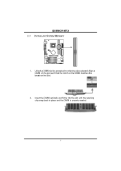
Insert the DIMM vertically and firmly into the slot until the retaining chip snap back in place and the DIMM is properly seated. 7 DIMM1 DIMM2 K8M800-M7A 2.3 INSTALLING SYSTEM MEMORY 1. Align a DIMM on the slot such that the notch on the DIMM matches the break on the Slot. 2. Unlock a DIMM slot by pressing the retaining clips outward.
Insert the DIMM vertically and firmly into the slot until the retaining chip snap back in place and the DIMM is properly seated. 7 DIMM1 DIMM2 K8M800-M7A 2.3 INSTALLING SYSTEM MEMORY 1. Align a DIMM on the slot such that the notch on the DIMM matches the break on the Slot. 2. Unlock a DIMM slot by pressing the retaining clips outward.
K8M800-M7A user's manual
Page 10
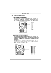
... drive, so you can connect up to IDE1. 40 39 2 IDE1 1 IDE2 8 The first hard drive should always be connected to four hard disk drives. K8M800-M7A 2.4 CONNECTORS AND SLOTS FDD1: Floppy Disk Connector The motherboard provides a standard floppy disk connector that provides PIO Mode 0~4, Bus Master, and Ultra DMA 33/66...
... drive, so you can connect up to IDE1. 40 39 2 IDE1 1 IDE2 8 The first hard drive should always be connected to four hard disk drives. K8M800-M7A 2.4 CONNECTORS AND SLOTS FDD1: Floppy Disk Connector The motherboard provides a standard floppy disk connector that provides PIO Mode 0~4, Bus Master, and Ultra DMA 33/66...
K8M800-M7A user's manual
Page 11
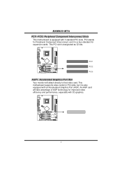
..., especially with an Accelerated Graphics Port (AGP). An AGP card will attach directly to that video card. This motherboard supports video cards for expansion cards. K8M800-M7A PCI1~PCI3: Peripheral Component Interconnect Slots This motherboard is designated as 32 bits. PCI stands for Peripheral Component Interconnect, and it is a bus standard for...
..., especially with an Accelerated Graphics Port (AGP). An AGP card will attach directly to that video card. This motherboard supports video cards for expansion cards. K8M800-M7A PCI1~PCI3: Peripheral Component Interconnect Slots This motherboard is designated as 32 bits. PCI stands for Peripheral Component Interconnect, and it is a bus standard for...
K8M800-M7A user's manual
Page 12
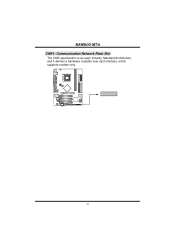
K8M800-M7A CNR1: Communication Network Riser Slot The CNR specification is an open Industry Standard Architecture, and it defines a hardware scalable riser card interface, which supports modem only. 10
K8M800-M7A CNR1: Communication Network Riser Slot The CNR specification is an open Industry Standard Architecture, and it defines a hardware scalable riser card interface, which supports modem only. 10
K8M800-M7A user's manual
Page 13
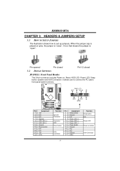
... set up jumpers. PWR_LED SLP On/Off ++ 2 1 +- When the jumper cap is placed on , Reset, HDD LED, Power LED, Sleep button, speaker and IrDA Connection. K8M800-M7A CHAPTER 3: HEADERS & JUMPERS SETUP 3.1 HOW TO SETUP JUMPERS The illustration shows how to connect the PC case's front panel switch functions. Pin opened Pin closed...
... set up jumpers. PWR_LED SLP On/Off ++ 2 1 +- When the jumper cap is placed on , Reset, HDD LED, Power LED, Sleep button, speaker and IrDA Connection. K8M800-M7A CHAPTER 3: HEADERS & JUMPERS SETUP 3.1 HOW TO SETUP JUMPERS The illustration shows how to connect the PC case's front panel switch functions. Pin opened Pin closed...
K8M800-M7A user's manual
Page 14
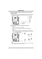
... Source Headers for USB Ports Pin 1-2 Close: JUSBV1: +5V for USB ports at front panel (JUSB1/JUSB2/JUSB3). JUSBV2: +5V for USB ports at JUSBLAN1. K8M800-M7A JUSB1/JUSB2/JUSB3: Headers for USB 2.0 Ports at Front Panel (JUSB3 is optional) This header allows user to support this function "Power-On system via...
... Source Headers for USB Ports Pin 1-2 Close: JUSBV1: +5V for USB ports at front panel (JUSB1/JUSB2/JUSB3). JUSBV2: +5V for USB ports at JUSBLAN1. K8M800-M7A JUSB1/JUSB2/JUSB3: Headers for USB 2.0 Ports at Front Panel (JUSB3 is optional) This header allows user to support this function "Power-On system via...
K8M800-M7A user's manual
Page 15
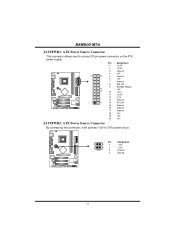
Pin Assignment 1 +3.3V 2 +3.3V 3 Ground 4 +5V 10 20 5 Ground 6 +5V 7 Ground 8 PW_OK 9 Standby Voltage +5V 10 +12V 11 +3.3V 12 -12V 13 Ground 1 11 14 PS_ON 15 Ground 16 Ground 17 Ground 18 -5V 19 +5V 20 +5V JATXPWR2: ATX Power Source Connector By connecting this connector, it will provide +12V to connect 20-pin power connector on the ATX power supply. K8M800-M7A JATXPWR1: ATX Power Source Connector This connector allows user to CPU power circuit. Pin Assignment 4 3 1 +12V 2 1 2 +12V 3 Ground 4 Ground 13
Pin Assignment 1 +3.3V 2 +3.3V 3 Ground 4 +5V 10 20 5 Ground 6 +5V 7 Ground 8 PW_OK 9 Standby Voltage +5V 10 +12V 11 +3.3V 12 -12V 13 Ground 1 11 14 PS_ON 15 Ground 16 Ground 17 Ground 18 -5V 19 +5V 20 +5V JATXPWR2: ATX Power Source Connector By connecting this connector, it will provide +12V to connect 20-pin power connector on the ATX power supply. K8M800-M7A JATXPWR1: ATX Power Source Connector This connector allows user to CPU power circuit. Pin Assignment 4 3 1 +12V 2 1 2 +12V 3 Ground 4 Ground 13
K8M800-M7A user's manual
Page 16
.../ Rear speaker Left JCDIN1: CD-ROM Audio-in Connector This connector allows user to connect the front audio output cable with the PC front panel. K8M800-M7A JFAUDIO1: Front Panel Audio Header This header allows user to connect the audio source from the variaty devices, like CD-ROM, DVD-ROM, PCI sound...
.../ Rear speaker Left JCDIN1: CD-ROM Audio-in Connector This connector allows user to connect the front audio output cable with the PC front panel. K8M800-M7A JFAUDIO1: Front Panel Audio Header This header allows user to connect the audio source from the variaty devices, like CD-ROM, DVD-ROM, PCI sound...
K8M800-M7A user's manual
Page 17
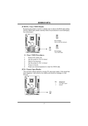
... 1 Case open status. Set the jumper to avoid damaging the motherboard. 1 3 Pin 1-2 Close: Normal Operation (default). 1 1 3 3 Pin 2-3 Close: Clear CMOS data. ※ Clear CMOS Procedures: 1. K8M800-M7A JCMOS1: Clear CMOS Header By placing the jumper on next boot-up. If the signal has been triggered, it will record to the CMOS and...
... 1 Case open status. Set the jumper to avoid damaging the motherboard. 1 3 Pin 1-2 Close: Normal Operation (default). 1 1 3 3 Pin 2-3 Close: Clear CMOS data. ※ Clear CMOS Procedures: 1. K8M800-M7A JCMOS1: Clear CMOS Header By placing the jumper on next boot-up. If the signal has been triggered, it will record to the CMOS and...
K8M800-M7A user's manual
Page 18
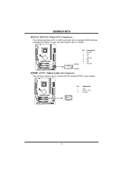
K8M800-M7A JSATA1~JSATA2: Serial ATA Connectors The motherboard has a PCI to SATA Controller with 2 channels SATA interface, it satisfies the SATA 1.0 spec and with transfer rate of 1.5GB/s. 741 Pin Assignment 1 Ground 2 TX+ 3 TX4 Ground 5 RX6 RX+ 7 Ground JSATA1 JSPDIF_OUT1: Digital Audio-out Connector This connector allows user to connect the PCI bracket SPDIF output header. 1 3 Pin Assignment 1 +5V 2 SPDIF_OUT 3 Ground 16
K8M800-M7A JSATA1~JSATA2: Serial ATA Connectors The motherboard has a PCI to SATA Controller with 2 channels SATA interface, it satisfies the SATA 1.0 spec and with transfer rate of 1.5GB/s. 741 Pin Assignment 1 Ground 2 TX+ 3 TX4 Ground 5 RX6 RX+ 7 Ground JSATA1 JSPDIF_OUT1: Digital Audio-out Connector This connector allows user to connect the PCI bracket SPDIF output header. 1 3 Pin Assignment 1 +5V 2 SPDIF_OUT 3 Ground 16
K8M800-M7A user's manual
Page 19
Confirm motherboard model and download the respectively BIOS from the Biostar website: www.biostar.com.tw 3. System will update BIOS automatically and restart. 9. Type "Awdflash xxxx.bf/sn/py/r" in DOS prompt. (xxxx means BIOS name.) 8. Make a bootable floppy ... when system boot-up the system, it means the BIOS contents are corrupted. Copy "AWDFLASH.exe" and respectively BIOS into floppy drive and press Enter. 6. K8M800-M7A CHAPTER 4: USEFUL HELP 4.1 AWARD BIOS BEEP CODE Beep Sound One long beep followed by virus, the Boot-Block function will help to restore BIOS. BIOS...
Confirm motherboard model and download the respectively BIOS from the Biostar website: www.biostar.com.tw 3. System will update BIOS automatically and restart. 9. Type "Awdflash xxxx.bf/sn/py/r" in DOS prompt. (xxxx means BIOS name.) 8. Make a bootable floppy ... when system boot-up the system, it means the BIOS contents are corrupted. Copy "AWDFLASH.exe" and respectively BIOS into floppy drive and press Enter. 6. K8M800-M7A CHAPTER 4: USEFUL HELP 4.1 AWARD BIOS BEEP CODE Beep Sound One long beep followed by virus, the Boot-Block function will help to restore BIOS. BIOS...
K8M800-M7A user's manual
Page 20
In this case, please double check: 1. Remove the power cord from power supply for seconds. 3. Wait for seconds. 2. K8M800-M7A B. The CPU cooler surface is over heated, the motherboard will shutdown automatically to relief the CPU protection function. 1. CPU fan is fulfilling with the CPU ...
In this case, please double check: 1. Remove the power cord from power supply for seconds. 3. Wait for seconds. 2. K8M800-M7A B. The CPU cooler surface is over heated, the motherboard will shutdown automatically to relief the CPU protection function. 1. CPU fan is fulfilling with the CPU ...
K8M800-M7A user's manual
Page 21
... at any time. Make sure correct information is Power light don't illuminate, fan securely plugged in setup. Run SETUP program and select correct drive types. K8M800-M7A 4.3 TROUBLESHOOTING Probable Solution 1. Replace cable. on . drive, can be booted from optical drive. 2. Check cable running from hard disk 2. All hard disks are lit, and...
... at any time. Make sure correct information is Power light don't illuminate, fan securely plugged in setup. Run SETUP program and select correct drive types. K8M800-M7A 4.3 TROUBLESHOOTING Probable Solution 1. Replace cable. on . drive, can be booted from optical drive. 2. Check cable running from hard disk 2. All hard disks are lit, and...
K8M800-M7A user's manual
Page 22
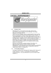
... hang, [WarpSpeeder™] technology assures the system stability by automatically rebooting the computer and then restart to power up CPU core voltage and Memory voltage. K8M800-M7A CHAPTER 5: WARPSPEEDER™ 5.1 INTRODUCTION [WarpSpeeder™], a new powerful control utility, features three user-friendly functions including Overclock Manager, Overvoltage Manager, and Hardware Monitor. If you...
... hang, [WarpSpeeder™] technology assures the system stability by automatically rebooting the computer and then restart to power up CPU core voltage and Memory voltage. K8M800-M7A CHAPTER 5: WARPSPEEDER™ 5.1 INTRODUCTION [WarpSpeeder™], a new powerful control utility, features three user-friendly functions including Overclock Manager, Overvoltage Manager, and Hardware Monitor. If you...