Bios Setup
Page 2
... this manual will to guide you through the options and settings in BIOS. APM Support T his system controls most of the input and output devices such as keyboard, mouse, serial ports and disk drives. ACPI Support AMI ACPI BIOS support Version 1.0/2.0 of Advanced Configuration and Power interface specifi cation (ACPI). T he power of CMOS RAM is supplied by this AMI BIOS. T his AMI BIOS supports Version 1.1&1.2 of the Advanced Power Management (APM) speci fication. BIOS activates at the first stag e o f the booting process, loading...
... this manual will to guide you through the options and settings in BIOS. APM Support T his system controls most of the input and output devices such as keyboard, mouse, serial ports and disk drives. ACPI Support AMI ACPI BIOS support Version 1.0/2.0 of Advanced Configuration and Power interface specifi cation (ACPI). T he power of CMOS RAM is supplied by this AMI BIOS. T his AMI BIOS supports Version 1.1&1.2 of the Advanced Power Management (APM) speci fication. BIOS activates at the first stag e o f the booting process, loading...
Bios Setup
Page 4
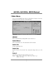
... Memory Shows system memory size, VGA shard memory will appear on the screen providing an overview of floppy disk drive installed in / None 3 Main Advanced BIOS SETUP UTILITY PCIPnP Boot Chipset Performance Exit System Overview AMI BIOS Version :01.01.01 Build Date:01/01/10 Use [ENTER], [TAB] or [SHIFT-TAB] to configure system Time. Options: 360K, 5.25 in / 1.2M, 5.25 in / 720K, 3.5 in / 1.44M, 3.5 in / 2.88M, 3.5 in your system. Change Field...
... Memory Shows system memory size, VGA shard memory will appear on the screen providing an overview of floppy disk drive installed in / None 3 Main Advanced BIOS SETUP UTILITY PCIPnP Boot Chipset Performance Exit System Overview AMI BIOS Version :01.01.01 Build Date:01/01/10 Use [ENTER], [TAB] or [SHIFT-TAB] to configure system Time. Options: 360K, 5.25 in / 1.2M, 5.25 in / 720K, 3.5 in / 1.44M, 3.5 in / 2.88M, 3.5 in your system. Change Field...

Bios Setup
Page 5
... A3 Device > SAT A4 Device > IDE Channel 1 Ma ster > IDE Channel 1 Sl ave Hard Disk Write Pr otect IDE D etect Time Ou t (Sec) BIOS S ETUP UTILITY [ Enhanced] [ Before PATA] [ SATA Pri, PA TA Sec] [ Disabled] [ 35] Options Disa bled Comp atible Enha nced S elect Screen S elect Item En terG o to enter the sub-menu of ID E/SAT A devices. Options: Enhanced (Default) / Compatible / Disabled Configure SATA Channels T his item allows you to control the SAT A channel configuration sequence. ATA/IDE Configuration...
... A3 Device > SAT A4 Device > IDE Channel 1 Ma ster > IDE Channel 1 Sl ave Hard Disk Write Pr otect IDE D etect Time Ou t (Sec) BIOS S ETUP UTILITY [ Enhanced] [ Before PATA] [ SATA Pri, PA TA Sec] [ Disabled] [ 35] Options Disa bled Comp atible Enha nced S elect Screen S elect Item En terG o to enter the sub-menu of ID E/SAT A devices. Options: Enhanced (Default) / Compatible / Disabled Configure SATA Channels T his item allows you to control the SAT A channel configuration sequence. ATA/IDE Configuration...
Bios Setup
Page 8
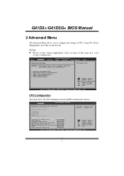
... Notice z Beware of that the BIOS automatically detects. Advanced BIOS SETUP UTILITY Configure advanced CPU settings Module Version:xx.xx Manufacturer:Intel Disable: Disable GV3 Enable: Enable GV3 Frequency : FSB Speed : Cache L1 : Cache L2 : Ratio Actual Value: Intel(R) SpeedStep(tm) tech [Disabled] Intel(R) C-STATE tech [Disabled] CIE Support [Disabled] Hardware Prefetcher [Enabled] Adjacent Cache Line Prefetch [Enabled] Max CPUID Value Limit [Disabled] Execute-Disable Bit Capability[Enabled] PECI [Enabled] Core Multi-Processing [Enabled] Select Screen Select Item +-
... Notice z Beware of that the BIOS automatically detects. Advanced BIOS SETUP UTILITY Configure advanced CPU settings Module Version:xx.xx Manufacturer:Intel Disable: Disable GV3 Enable: Enable GV3 Frequency : FSB Speed : Cache L1 : Cache L2 : Ratio Actual Value: Intel(R) SpeedStep(tm) tech [Disabled] Intel(R) C-STATE tech [Disabled] CIE Support [Disabled] Hardware Prefetcher [Enabled] Adjacent Cache Line Prefetch [Enabled] Max CPUID Value Limit [Disabled] Execute-Disable Bit Capability[Enabled] PECI [Enabled] Core Multi-Processing [Enabled] Select Screen Select Item +-

Bios Setup
Page 9
... dynamically changed by lowering CPU frequen cy while the processor is not working. Options: Disabled (Default) / Enabled Hardware Prefetcher T he processor has a h ardw are prefetch er that automatically analy zes its capabilities. Options: Enabled (Default) / Disabled Adj acent Cache Line Prefetch T he processor has a hardw are adjacent cache line prefet ch mech anism that allows the clock speed o f the processor to save power and decrease heat by software. Options: Disabled (Default) / Enabled Intel...
... dynamically changed by lowering CPU frequen cy while the processor is not working. Options: Disabled (Default) / Enabled Hardware Prefetcher T he processor has a h ardw are prefetch er that automatically analy zes its capabilities. Options: Enabled (Default) / Disabled Adj acent Cache Line Prefetch T he processor has a hardw are adjacent cache line prefet ch mech anism that allows the clock speed o f the processor to save power and decrease heat by software. Options: Disabled (Default) / Enabled Intel...

Bios Setup
Page 10
Options: Enabled (Default) / Disabled SuperIO Configuration Advanced BIOS SETUP UTILITY Configure ITE8721 Super IO Chipset Onboard Floppy Controller Serial Port1 Address Parallel Port Address Parallel Port Mode Parallel Port IRQ Keyboard PowerOn Mouse PowerOn Restore on the system board and you wish to use it. G41D3+/G41D3G+ BIOS M anual Execute-Disable Bit Capability T his item allows you to configure th e Execut e Disabled Bit function, which supports Platform Environment Control Interface for better therm al management. Options: Enabled (Default) / Disabled PECI T his ...
Options: Enabled (Default) / Disabled SuperIO Configuration Advanced BIOS SETUP UTILITY Configure ITE8721 Super IO Chipset Onboard Floppy Controller Serial Port1 Address Parallel Port Address Parallel Port Mode Parallel Port IRQ Keyboard PowerOn Mouse PowerOn Restore on the system board and you wish to use it. G41D3+/G41D3G+ BIOS M anual Execute-Disable Bit Capability T his item allows you to configure th e Execut e Disabled Bit function, which supports Platform Environment Control Interface for better therm al management. Options: Enabled (Default) / Disabled PECI T his ...
Bios Setup
Page 12
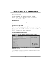
... / Ctrl+F5 / Ctrl+F6 Mouse PowerOn T his item allows you to the status before power failure or interrupt occurs. Options: Enabled (Default) / Disabled 11 Advanced BIOS SETUP UTILITY Hardware Health Configuration H/W Health Function [Enabled] Shutdown Temperature Function[Disabled] Enables Hardware Health Monitoring Device. G41D3+/G41D3G+ BIOS M anual Stroke Keys Selected T his item will restore the system to control the mouse power on AC Power Loss T his item shows the system temperature, fan speed, and voltage information.
... / Ctrl+F5 / Ctrl+F6 Mouse PowerOn T his item allows you to the status before power failure or interrupt occurs. Options: Enabled (Default) / Disabled 11 Advanced BIOS SETUP UTILITY Hardware Health Configuration H/W Health Function [Enabled] Shutdown Temperature Function[Disabled] Enables Hardware Health Monitoring Device. G41D3+/G41D3G+ BIOS M anual Stroke Keys Selected T his item will restore the system to control the mouse power on AC Power Loss T his item shows the system temperature, fan speed, and voltage information.
Bios Setup
Page 15
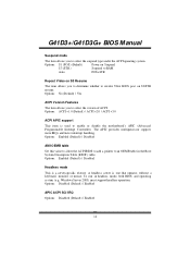
... the version of ACPI. Options: Enabled (Default) / Disabled AMI OEMB table Set this value to allow the ACPIBIOS to add a pointer to enable or disable the motherboard's APIC (Advan ced Programmable Interrupt Controller). Options: S1 (POS) (Default) Power on Suspend S3 (ST R) Suspend to RAM Auto POS+STR Repost Video on S3/ST R resume. G41D3+/G41D3G+ BIOS M anual Suspend mode T he item allows you to determine whether to invoke VGA BIOS post on...
... the version of ACPI. Options: Enabled (Default) / Disabled AMI OEMB table Set this value to allow the ACPIBIOS to add a pointer to enable or disable the motherboard's APIC (Advan ced Programmable Interrupt Controller). Options: S1 (POS) (Default) Power on Suspend S3 (ST R) Suspend to RAM Auto POS+STR Repost Video on S3/ST R resume. G41D3+/G41D3G+ BIOS M anual Suspend mode T he item allows you to determine whether to invoke VGA BIOS post on...
Bios Setup
Page 16
.... Options: Disabled (Default) / Enabled Resume On RTC Alarm When " Enabled", you can set the memory address of HPET . Options: Disabled (Default) / Enabled RTC Alarm Date (Days) You can choose the system boot up . Options: FED00000h (Default) / FED01000h / FED02000h / FED03000h Resume On Ring T his item allows you to enable if applicabl e. Set the Wake on LAN (WOL) jumper on motherboard to control the wake on LAN function. For this function to enable or disabled the HPET. G41D3+/G41D3G+ BIOS...
.... Options: Disabled (Default) / Enabled Resume On RTC Alarm When " Enabled", you can set the memory address of HPET . Options: Disabled (Default) / Enabled RTC Alarm Date (Days) You can choose the system boot up . Options: FED00000h (Default) / FED01000h / FED02000h / FED03000h Resume On Ring T his item allows you to enable if applicabl e. Set the Wake on LAN (WOL) jumper on motherboard to control the wake on LAN function. For this function to enable or disabled the HPET. G41D3+/G41D3G+ BIOS...
Bios Setup
Page 17
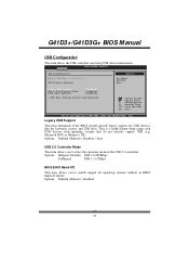
... r USB devices like the keyboard, mouse, and USB drive. Options: Enabled (Default) / Disabled 16 Legacy USB Support T his is a useful feature when using USB device information. Options: Enabled (Default) / Disabled / Auto USB 2.0 Controller Mode T his item shows the USB controller and using such USB devices with operating systems that do not natively support USB (e.g. C hange Option F1 G eneral Help F1 0 S ave and Exit ES C E xit vxx.xx (C)C opyright 198 5-200x, Amer ican Megatre nds, Inc. Microso ft DOS or Windows NT). G41D3+/G41D3G+ BIOS M anual USB Configuration...
... r USB devices like the keyboard, mouse, and USB drive. Options: Enabled (Default) / Disabled 16 Legacy USB Support T his is a useful feature when using USB device information. Options: Enabled (Default) / Disabled / Auto USB 2.0 Controller Mode T his item shows the USB controller and using such USB devices with operating systems that do not natively support USB (e.g. C hange Option F1 G eneral Help F1 0 S ave and Exit ES C E xit vxx.xx (C)C opyright 198 5-200x, Amer ican Megatre nds, Inc. Microso ft DOS or Windows NT). G41D3+/G41D3G+ BIOS M anual USB Configuration...
Bios Setup
Page 20
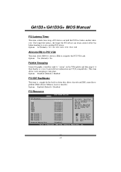
... devices. Options: Disabled (Default) / Enabled PCI IDE BusMaster T his item controls how long a PCI device can retain control of the bus before another PCI device. Change Option F1 General Help F10 Save and Exit ESC Exit vxx.xx (C)Copyright 1985-200x, American Megatrends, Inc. 19 G41D3+/G41D3G+ BIOS M anual PCI Latency Timer T his item is a toggle for the built-in driver that allows the onbo ard ID E controller to perform DMA (Direct Memory Access...
... devices. Options: Disabled (Default) / Enabled PCI IDE BusMaster T his item controls how long a PCI device can retain control of the bus before another PCI device. Change Option F1 General Help F10 Save and Exit ESC Exit vxx.xx (C)Copyright 1985-200x, American Megatrends, Inc. 19 G41D3+/G41D3G+ BIOS M anual PCI Latency Timer T his item is a toggle for the built-in driver that allows the onbo ard ID E controller to perform DMA (Direct Memory Access...

Bios Setup
Page 26
... allows you to use this function. Options: Enabled,32MB (Default) / Enabled,64MB / Enabled,128MB / Disabled 25 G41D3+/G41D3G+ BIOS M anual North Bridge Configuration BIOS S ETUP UTILITY Chips et North Bridge Chips et Configura tion Memor y Remap Featu re PCI MMIO Allocat ion: Memor y Hole [Enabled] [Disabled] Initi ate Graphic A dapter IGD G raphics Mode Select IGD G TT Graphics m emory size [PEG/PCI] [Enabled, 3 2MB] [No VT mode , 2MB] PEG P ort Configura tion PEG Port [Auto] > Vid eo...
... allows you to use this function. Options: Enabled,32MB (Default) / Enabled,64MB / Enabled,128MB / Disabled 25 G41D3+/G41D3G+ BIOS M anual North Bridge Configuration BIOS S ETUP UTILITY Chips et North Bridge Chips et Configura tion Memor y Remap Featu re PCI MMIO Allocat ion: Memor y Hole [Enabled] [Disabled] Initi ate Graphic A dapter IGD G raphics Mode Select IGD G TT Graphics m emory size [PEG/PCI] [Enabled, 3 2MB] [No VT mode , 2MB] PEG P ort Configura tion PEG Port [Auto] > Vid eo...

Bios Setup
Page 28
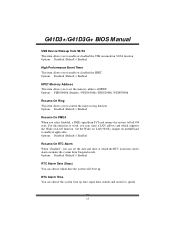
...you to enable or disable the Onboard LAN. If the BIOS has high speed USB support built in, the support will be automatically turn on when high speed device were attached. Options: 8 USB Ports (Default) / 6 USB Ports / 4 USB Ports / 2 USB Ports / Disabled USB 2.0 Controller T his item allows you to select the Audio support. G41D3+/G41D3G+ BIOS M anual South Bridge Configuration BIOS SETU P U TILITY Chipset South Bridge C hipset Configuratio n USB Functions USB 2.0 Contro ller Audio Controll er [8 USB Ports] [E nabled] [A zalia] Onboard Lan Co ntrol Onboard Lan Bo ot ROM MAC ID...
...you to enable or disable the Onboard LAN. If the BIOS has high speed USB support built in, the support will be automatically turn on when high speed device were attached. Options: 8 USB Ports (Default) / 6 USB Ports / 4 USB Ports / 2 USB Ports / Disabled USB 2.0 Controller T his item allows you to select the Audio support. G41D3+/G41D3G+ BIOS M anual South Bridge Configuration BIOS SETU P U TILITY Chipset South Bridge C hipset Configuratio n USB Functions USB 2.0 Contro ller Audio Controll er [8 USB Ports] [E nabled] [A zalia] Onboard Lan Co ntrol Onboard Lan Bo ot ROM MAC ID...
Bios Setup
Page 30
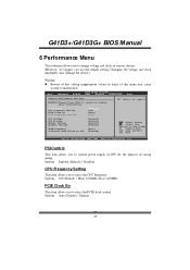
... PSI Control CPU Frequency Setting PCIE Clock By PCIE Frequency Setting [Enabled] [200] [Auto] [100] CPU Voltage FSB Voltage Memory Voltage Chipset Voltage DRAM Frequency Configure DRAM Timing by SPD [Default] [Default] [Default] [Default] [Auto] [Enabled] Select Screen Select Item EnterGo to select the CPU Frequency. Options: Enabled (Default) / Disabled CPU Frequency Setting T his item allows you to control power supply of CPU for the purpose of saving energy. Max= 600MHz PCIE Clock By T his item allows you use the default setting. Changing the voltage and clock...
... PSI Control CPU Frequency Setting PCIE Clock By PCIE Frequency Setting [Enabled] [200] [Auto] [100] CPU Voltage FSB Voltage Memory Voltage Chipset Voltage DRAM Frequency Configure DRAM Timing by SPD [Default] [Default] [Default] [Default] [Auto] [Enabled] Select Screen Select Item EnterGo to select the CPU Frequency. Options: Enabled (Default) / Disabled CPU Frequency Setting T his item allows you to control power supply of CPU for the purpose of saving energy. Max= 600MHz PCIE Clock By T his item allows you use the default setting. Changing the voltage and clock...
Bios Setup
Page 34
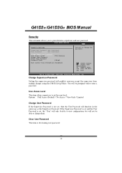
... Options: Full Access (Default) / No Access / View Only / Limited Change User Password If the Supervisor Password is set the user level. Ifthe Supervisor Password is set and the User Password is not set, then the User Password will prohibit everyone except the supervisor from making changes using the CMOS Setup Utility. BIOS SETU P U TILITY Exit Security Setti ngs Supervisor Pas sword :Not Installe d User Password :Not Installe d Change Supervi sor Password User Access Le vel Change User Pa ssword Clear User Pas sword Password Check [Ful l Access] [Set...
... Options: Full Access (Default) / No Access / View Only / Limited Change User Password If the Supervisor Password is set the user level. Ifthe Supervisor Password is set and the User Password is not set, then the User Password will prohibit everyone except the supervisor from making changes using the CMOS Setup Utility. BIOS SETU P U TILITY Exit Security Setti ngs Supervisor Pas sword :Not Installe d User Password :Not Installe d Change Supervi sor Password User Access Le vel Change User Pa ssword Clear User Pas sword Password Check [Ful l Access] [Set...
Setup Manual
Page 4
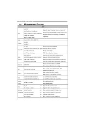
...Floppy drives x1 Each connector supports 1 Printer port x1 Connects to 3.0 Gb/s. Motherboard Manual 1.3 MOTHERBOARD FEATURES SPEC LGA 775 Supports Hyper-Threading / Execute Disable Bit / Intel Core2Duo / Core2Quad / Enhanced Intel SpeedStep® / Intel Architecture-64 / CPU Pentium Dual-Core / Celeron Dual-Core / Extended Memory 64 Technology / Virtualization Celeron 4xx processor Technology (Maximum Watt: 95W) FSB Support 800 / 1066 / 1333 MHz Chipset Intel G41 Intel ICH7 ITE 8721 Environment Control initiatives, Provides the most commonly used legacy Hardware Monitor...
...Floppy drives x1 Each connector supports 1 Printer port x1 Connects to 3.0 Gb/s. Motherboard Manual 1.3 MOTHERBOARD FEATURES SPEC LGA 775 Supports Hyper-Threading / Execute Disable Bit / Intel Core2Duo / Core2Quad / Enhanced Intel SpeedStep® / Intel Architecture-64 / CPU Pentium Dual-Core / Celeron Dual-Core / Extended Memory 64 Technology / Virtualization Celeron 4xx processor Technology (Maximum Watt: 95W) FSB Support 800 / 1066 / 1333 MHz Chipset Intel G41 Intel ICH7 ITE 8721 Environment Control initiatives, Provides the most commonly used legacy Hardware Monitor...
Setup Manual
Page 5
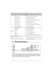
...to D-SUB monitor x1 Connect to RJ-45 ethernet cable x4 Connect to USB devices x3 Provide Audio-In/Out and microphone connection Biostar reserves the right to the audio port, please use the Line In (blue) and Mic In (Pink) audio jack. 3 SATA Connector Front Panel Connector Front Audio Connector CPU Fan Header System Fan Header Clear CMOS Header USB Connector Power Connector (24pin) Power Connector (4pin) PS/2 Keyboard PS/2 Mouse Back Panel VGA port I/O LAN port USB Port Audio Jack Board Size 182 (W) x 235 (L) mm OS Support Windows 2000 / XP / Vista / 7 G41D3+/G41D3G+ SPEC x4...
...to D-SUB monitor x1 Connect to RJ-45 ethernet cable x4 Connect to USB devices x3 Provide Audio-In/Out and microphone connection Biostar reserves the right to the audio port, please use the Line In (blue) and Mic In (Pink) audio jack. 3 SATA Connector Front Panel Connector Front Audio Connector CPU Fan Header System Fan Header Clear CMOS Header USB Connector Power Connector (24pin) Power Connector (4pin) PS/2 Keyboard PS/2 Mouse Back Panel VGA port I/O LAN port USB Port Audio Jack Board Size 182 (W) x 235 (L) mm OS Support Windows 2000 / XP / Vista / 7 G41D3+/G41D3G+ SPEC x4...
Setup Manual
Page 14
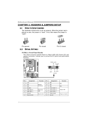
... Reset, HDD LED, Power LED, and speaker connection. It allows user to set up jumpers. Pin opened Pin closed 3.2 DETAIL SETTINGS Pin1-2 closed PANEL1: Front Panel Header This 16-pin connector includes Power-on pins, the jumper is "close", if not, that means the jumper is "open". PWR_LED On/Off 9 ++ 16 1 8 + SPK RST HLED Pin Assignment 1 +5V 2 N/A 3 N/A 4 Speaker 5 HDD LED (+) 6 HDD LED (-) 7 Ground 8 Reset control Function Pin 9 Speaker 10 Connector 11 12 Hard drive 13 LED 14 15 Reset button 16 Assignment N/A N/A N/A Power LED (+) Power LED (+) Power LED...
... Reset, HDD LED, Power LED, and speaker connection. It allows user to set up jumpers. Pin opened Pin closed 3.2 DETAIL SETTINGS Pin1-2 closed PANEL1: Front Panel Header This 16-pin connector includes Power-on pins, the jumper is "close", if not, that means the jumper is "open". PWR_LED On/Off 9 ++ 16 1 8 + SPK RST HLED Pin Assignment 1 +5V 2 N/A 3 N/A 4 Speaker 5 HDD LED (+) 6 HDD LED (-) 7 Ground 8 Reset control Function Pin 9 Speaker 10 Connector 11 12 Hard drive 13 LED 14 15 Reset button 16 Assignment N/A N/A N/A Power LED (+) Power LED (+) Power LED...
Setup Manual
Page 26
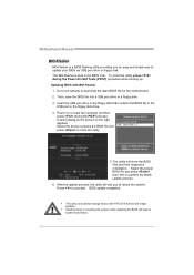
... Power-On Self Tests (POST) procedure while booting up. BIOS update completes. z Shutting down or resetting the system while updating the BIOS will show the BIOS files and their respective information. Motherboard Manual BIO-Flasher BIO-Flasher is built in the BIOS chip. Go to the website to enter the utility. 5. Then, save the BIOS file into a USB pen drive or a floppy disk. 3. Select the device contains the BIOS file and press to download the latest BIOS file for the motherboard. 2. Power...
... Power-On Self Tests (POST) procedure while booting up. BIOS update completes. z Shutting down or resetting the system while updating the BIOS will show the BIOS files and their respective information. Motherboard Manual BIO-Flasher BIO-Flasher is built in the BIOS chip. Go to the website to enter the utility. 5. Then, save the BIOS file into a USB pen drive or a floppy disk. 3. Select the device contains the BIOS file and press to download the latest BIOS file for the motherboard. 2. Power...
Setup Manual
Page 27
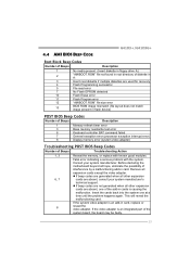
... in floppy drive A:) 2 "AMIBOOT.ROM" file not found in root directory of diskette in A: 3 Insert next diskette if multiple diskettes are absent, consult your system manufacturer. Consult your system manufacturer's technical support. z If beep codes are generated when all other expansion 6, 7 cards are used for recovery 4 Flash Programming successful 5 File read /write test error 6 Keyboard controller BAT command failed 7 General exception error (processor exception interrupt error) 8 Display memory error (system video adapter) Troubleshooting POST BIOS Beep Codes...
... in floppy drive A:) 2 "AMIBOOT.ROM" file not found in root directory of diskette in A: 3 Insert next diskette if multiple diskettes are absent, consult your system manufacturer. Consult your system manufacturer's technical support. z If beep codes are generated when all other expansion 6, 7 cards are used for recovery 4 Flash Programming successful 5 File read /write test error 6 Keyboard controller BAT command failed 7 General exception error (processor exception interrupt error) 8 Display memory error (system video adapter) Troubleshooting POST BIOS Beep Codes...


