Update Manual
Page 1
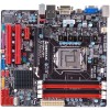
... your agreement to enter BIOS setup. After entering the BIOS setup, please go to the Save & Exit, using the Restore Defaults function to load Optimized Defaults, and select Save Changes and Reset to update the BIOS: BIOS Update Utility, BIOS Online Update Utility and BIOS Flasher. BIOS update utility 1. A warning message will take several minutes, please be patient. 6. While the system boots up and the full screen logo shows up to request your BIOS file in the system...
... your agreement to enter BIOS setup. After entering the BIOS setup, please go to the Save & Exit, using the Restore Defaults function to load Optimized Defaults, and select Save Changes and Reset to update the BIOS: BIOS Update Utility, BIOS Online Update Utility and BIOS Flasher. BIOS update utility 1. A warning message will take several minutes, please be patient. 6. While the system boots up and the full screen logo shows up to request your BIOS file in the system...
Update Manual
Page 2
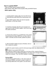
... enter BIOS setup. After entering the BIOS setup, please go to program (update) the BIOS or not. Then, the BIOS Update is a new BIOS version, the utility will be asked to the Save & Exit, using this function. 3. An open dialog will be asked you to start the online update procedure. 5. After the download is connected to the internet before using the Restore Defaults function to load Optimized Defaults, and select Save Changes and Reset...
... enter BIOS setup. After entering the BIOS setup, please go to program (update) the BIOS or not. Then, the BIOS Update is a new BIOS version, the utility will be asked to the Save & Exit, using this function. 3. An open dialog will be asked you to start the online update procedure. 5. After the download is connected to the internet before using the Restore Defaults function to load Optimized Defaults, and select Save Changes and Reset...
Update Manual
Page 3
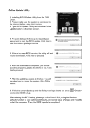
... USB port. 4. The information and pictures described above about the software are for the motherboard. 2. This utility only allows storage device with BIOSTAR BIOS Flasher 1. Then, the BIOS Update is completed, asking you to be slightly different from this manual. Power on board may be changed without notice. After entering the POST screen, the BIOSFLASHER utility pops out. Insert the USB pen drive that contains the BIOS file to download the latest BIOS file for your BIOS...
... USB port. 4. The information and pictures described above about the software are for the motherboard. 2. This utility only allows storage device with BIOSTAR BIOS Flasher 1. Then, the BIOS Update is completed, asking you to be slightly different from this manual. Power on board may be changed without notice. After entering the POST screen, the BIOSFLASHER utility pops out. Insert the USB pen drive that contains the BIOS file to download the latest BIOS file for your BIOS...
Setup Manual
Page 4
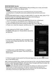
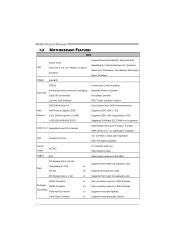
...cards PCI Express Gen2 x 1 slot x1 Supports PCI-E Gen2 x1 expansion cards SATA3 Connector On Board SATA2 Connector Connectors Front Panel Connector x1 Each connector supports 1 SATA3 devices x5 Each connector supports 1 SATA2 devices x1 Supports front panel facilities Front Audio Connector x1 Supports front panel audio function 2 Motherboard Manual 1.3 MOTHERBOARD FEATURES SPEC Supports Execute Disable Bit / Enhanced Intel Socket 1155 SpeedStep® / Intel Architecture-64 / Extended CPU Intel Core i7 / i5 / i3 / Pentium / Celeron Memory 64 Technology / Virtualization...
...cards PCI Express Gen2 x 1 slot x1 Supports PCI-E Gen2 x1 expansion cards SATA3 Connector On Board SATA2 Connector Connectors Front Panel Connector x1 Each connector supports 1 SATA3 devices x5 Each connector supports 1 SATA2 devices x1 Supports front panel facilities Front Audio Connector x1 Supports front panel audio function 2 Motherboard Manual 1.3 MOTHERBOARD FEATURES SPEC Supports Execute Disable Bit / Enhanced Intel Socket 1155 SpeedStep® / Intel Architecture-64 / Extended CPU Intel Core i7 / i5 / i3 / Pentium / Celeron Memory 64 Technology / Virtualization...

Setup Manual
Page 5
...connection ATX Biostar reserves the right to USB3.0 devices x3 Provide Audio-In/Out and Mic. CPU Fan Header System Fan Header Clear CMOS Header USB2.0 Connector USB3.0 Connector Consumer IR Connector Printer Port Connector Serial Port Connector S/PDIF out Connector Power Connector (24pin) Power Connector (4pin) PS/2 Keyboard HDMI Port VGA Port Back Panel DVI Port I/O LAN port USB2.0 Port USB3.0 Port Audio Jack Board Size 220 (W) x 244 (L) mm OS Support Windows XP / Vista / 7 SPEC B75MU3+ x1 CPU Fan power supply (with Smart Fan function) x1 System Fan Power supply...
...connection ATX Biostar reserves the right to USB3.0 devices x3 Provide Audio-In/Out and Mic. CPU Fan Header System Fan Header Clear CMOS Header USB2.0 Connector USB3.0 Connector Consumer IR Connector Printer Port Connector Serial Port Connector S/PDIF out Connector Power Connector (24pin) Power Connector (4pin) PS/2 Keyboard HDMI Port VGA Port Back Panel DVI Port I/O LAN port USB2.0 Port USB3.0 Port Audio Jack Board Size 220 (W) x 244 (L) mm OS Support Windows XP / Vista / 7 SPEC B75MU3+ x1 CPU Fan power supply (with Smart Fan function) x1 System Fan Power supply...
Setup Manual
Page 16
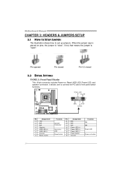
...N/A 4 Speaker 5 HDD LED (+) 6 HDD LED (-) 7 Ground 8 Reset control Function Pin 9 Speaker 10 Connector 11 12 Hard drive 13 LED 14 Reset button 15 16 Assignment N/A N/A N/A Power LED (+) Power LED (+) Power LED (-) Power button Ground Function N/A N/A Power LED Power-on pins, the jumper is "close", if not, that means the jumper is "open". When the jumper cap is placed on button 14 It allows user to set up jumpers. Pin opened Pin closed Pin1-2 closed 3.2 DETAIL SETTINGS PANEL1: Front Panel Header This 16-pin connector includes Power-on, Reset, HDD LED, Power LED, and...
...N/A 4 Speaker 5 HDD LED (+) 6 HDD LED (-) 7 Ground 8 Reset control Function Pin 9 Speaker 10 Connector 11 12 Hard drive 13 LED 14 Reset button 15 16 Assignment N/A N/A N/A Power LED (+) Power LED (+) Power LED (-) Power button Ground Function N/A N/A Power LED Power-on pins, the jumper is "close", if not, that means the jumper is "open". When the jumper cap is placed on button 14 It allows user to set up jumpers. Pin opened Pin closed Pin1-2 closed 3.2 DETAIL SETTINGS PANEL1: Front Panel Header This 16-pin connector includes Power-on, Reset, HDD LED, Power LED, and...

Setup Manual
Page 29
... are used for recovery 4 Flash Programming successful 5 File read error 7 No Flash EPROM detected 10 Flash Erase error 11 Flash Program error 12 "AMIBOOT.ROM" file size error 13 BIOS ROM image mismatch (file layout does not match image present in flash device) POST BIOS Beep Codes Number of Beeps Description 1 Memory refresh timer error 3 Base memory read/write test error 6 Keyboard controller BAT command failed 7 General exception error (processor exception interrupt error) 8 Display memory error (system video adapter) Troubleshooting POST BIOS Beep Codes Number...
... are used for recovery 4 Flash Programming successful 5 File read error 7 No Flash EPROM detected 10 Flash Erase error 11 Flash Program error 12 "AMIBOOT.ROM" file size error 13 BIOS ROM image mismatch (file layout does not match image present in flash device) POST BIOS Beep Codes Number of Beeps Description 1 Memory refresh timer error 3 Base memory read/write test error 6 Keyboard controller BAT command failed 7 General exception error (processor exception interrupt error) 8 Display memory error (system video adapter) Troubleshooting POST BIOS Beep Codes Number...
Setup Manual
Page 30
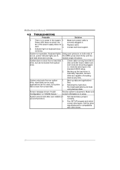
... for compatibility with other drives. 28 Make sure power cable is inoperative. Replace cable. System does not boot from disk to boot from a hard disk. Re-install applications and data using backup disks. the securely plugged in the standard CMOS setup. 2. Check cable running . Make sure correct information is no power in the system. 1. Run SETUP program and select correct drive types. drive, but system 2. Backing up data and applications files. Set master/slave jumpers correctly. Keyboard lights Using...
... for compatibility with other drives. 28 Make sure power cable is inoperative. Replace cable. System does not boot from disk to boot from a hard disk. Re-install applications and data using backup disks. the securely plugged in the standard CMOS setup. 2. Check cable running . Make sure correct information is no power in the system. 1. Run SETUP program and select correct drive types. drive, but system 2. Backing up data and applications files. Set master/slave jumpers correctly. Keyboard lights Using...

Bios Manual
Page 2
... motherboard. It provides ASL code for power management and device configuration capabilities as keyboard, mouse, serial ports and disk drives. PCI Bus Support This AMI UEFI BIOS also supports Version 2.3 of the booting process, loading and executing the operating system. UEFI BIOS determines what a computer can do without accessing programs from a disk. Plug and Play Support This AMI UEFI BIOS supports the Plug and Play Version 1.0A specification. This system controls most of the input and output devices such as defined in the ACPI specification...
... motherboard. It provides ASL code for power management and device configuration capabilities as keyboard, mouse, serial ports and disk drives. PCI Bus Support This AMI UEFI BIOS also supports Version 2.3 of the booting process, loading and executing the operating system. UEFI BIOS determines what a computer can do without accessing programs from a disk. Plug and Play Support This AMI UEFI BIOS supports the Plug and Play Version 1.0A specification. This system controls most of the input and output devices such as defined in the ACPI specification...

Bios Manual
Page 6
...(Default) / Enabled 5 B75MU3+ UEFI BIOS Manual PCI ROM Priority In case of multiple option ROMs (Legacy and EFI Compatible), this item specifies what PCI Option ROM to launch Options: Legacy ROM (Default) / EFI Compatible ROM Above 4G Decoding Enables or disables 64bit capable device to be programmed into PCI Latency Timer Register. Options: Disabled (Default) / Enabled PERR# Generation Enables or disables PCI device to generate SERR#. Options: Disabled (Default) / Enabled PCI Latency Timer This item sets the value to be decoded in above 4G address space (only if system support 64 bit...
...(Default) / Enabled 5 B75MU3+ UEFI BIOS Manual PCI ROM Priority In case of multiple option ROMs (Legacy and EFI Compatible), this item specifies what PCI Option ROM to launch Options: Legacy ROM (Default) / EFI Compatible ROM Above 4G Decoding Enables or disables 64bit capable device to be programmed into PCI Latency Timer Register. Options: Disabled (Default) / Enabled PERR# Generation Enables or disables PCI device to generate SERR#. Options: Disabled (Default) / Enabled PCI Latency Timer This item sets the value to be decoded in above 4G address space (only if system support 64 bit...
Bios Manual
Page 8
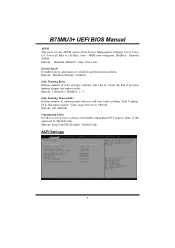
...; Disables ASPM. Options: Disabled (Default) / Enabled Link Training Retry Defines number of extended synchronization patterns. Force all links to 1000 uS. Options: 100 (Default) Unpopulated Links In order to save power, software will wait before polling 'Link Training' bit in link status register. Auto - Options: Keep Link ON (Default) / Disable Link ACPI Settings 7 Options: 5 (Default) / Disabled / 2 / 3 Link Training Timeout(uS) Defines number of microseconds software will disable unpopulated PCI Express links, if this option set...
...; Disables ASPM. Options: Disabled (Default) / Enabled Link Training Retry Defines number of extended synchronization patterns. Force all links to 1000 uS. Options: 100 (Default) Unpopulated Links In order to save power, software will wait before polling 'Link Training' bit in link status register. Auto - Options: Keep Link ON (Default) / Disable Link ACPI Settings 7 Options: 5 (Default) / Disabled / 2 / 3 Link Training Timeout(uS) Defines number of microseconds software will disable unpopulated PCI Express links, if this option set...

Bios Manual
Page 9
... the system boot up . Power ON: Powering on by alarm event. Powering on the hr::min::sec specified. Options: S1 (CPU Stop Clock) (Default) / Suspend Disabled / S3 (Suspend to wake on the system immediately when power returns. Options: Disabled (Default) / Enabled 8 Options: Disabled (Default) / Enabled Wake system with Fixed Time This item enables or disables the system to RAM) Restore AC Power Loss This setting specifies how your system should behave after power recovers. B75MU3+ UEFI BIOS Manual ACPI Sleep State This...
... the system boot up . Power ON: Powering on by alarm event. Powering on the hr::min::sec specified. Options: S1 (CPU Stop Clock) (Default) / Suspend Disabled / S3 (Suspend to wake on the system immediately when power returns. Options: Disabled (Default) / Enabled 8 Options: Disabled (Default) / Enabled Wake system with Fixed Time This item enables or disables the system to RAM) Restore AC Power Loss This setting specifies how your system should behave after power recovers. B75MU3+ UEFI BIOS Manual ACPI Sleep State This...

Bios Manual
Page 11
..., Windows XP SP2, SuSE Linux 9.2, RedHat Enterprise 3 Update 3.). This reduces cache latency by making the next cache line immediately available if the processor requires it must first query the processor to be required in each processor package. Options: Enabled (Default) / Disabled 10 Before it can do so, it as well. Options: Enabled (Default) / Disabled Intel Virtualization Tech Virtualization Technology can provide the operating system. Options: Disabled (Default) / Enabled Execute-Disable Bit XD...
..., Windows XP SP2, SuSE Linux 9.2, RedHat Enterprise 3 Update 3.). This reduces cache latency by making the next cache line immediately available if the processor requires it must first query the processor to be required in each processor package. Options: Enabled (Default) / Disabled 10 Before it can do so, it as well. Options: Enabled (Default) / Disabled Intel Virtualization Tech Virtualization Technology can provide the operating system. Options: Disabled (Default) / Enabled Execute-Disable Bit XD...

Bios Manual
Page 25
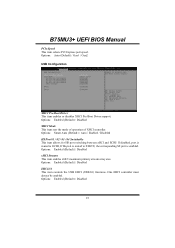
... the legacy option ROM for legacy mass storage devices with option ROM. B75MU3+ UEFI BIOS Manual on board lan option rom This item enables or disables onboard LAN option ROM. Options: Enabled (Default) / Disabled / Enabled when no UEFI Driver PCI Express Configuration Onboard PCIE Giga LAN / PEX1_1Slot This item controls the PCI Express Root Port. Options: Disabled (Default) / L0s / L1 / L0sL1 / Auto 24 Options: Disabled (Default) / Enabled Launch Storage OpROM This item enables or disables boot Options for video devices. Options: Enabled (Default) / Disabled ASPM This item sets PCI...
... the legacy option ROM for legacy mass storage devices with option ROM. B75MU3+ UEFI BIOS Manual on board lan option rom This item enables or disables onboard LAN option ROM. Options: Enabled (Default) / Disabled / Enabled when no UEFI Driver PCI Express Configuration Onboard PCIE Giga LAN / PEX1_1Slot This item controls the PCI Express Root Port. Options: Disabled (Default) / L0s / L1 / L0sL1 / Auto 24 Options: Disabled (Default) / Enabled Launch Storage OpROM This item enables or disables boot Options for video devices. Options: Enabled (Default) / Disabled ASPM This item sets PCI...
Bios Manual
Page 26
... Disabled XHCI Mode This item sets the mode of operation of XHCI controller. Options: Enabled (Default) / Disabled EHCI1/2 This item controls the USB EHCI (USB2.0) functions. Options: Smart Auto (Default) / Auto / Enabled / Disabled HS Port #1 / #2 / #3 / #4 Switchable This item allows for HS port switching between xHCI and ECHI/ If disabled, port is routed to ECHI, If Hs port is routed to XHCIU, the corresponding SS port is enabled. B75MU3+ UEFI BIOS Manual PCIe Speed This item selects PCI Express port speed. Options: Auto (Default) / Gen1 / Gen2 USB Configuration XHCI Pre-Boot Driver...
... Disabled XHCI Mode This item sets the mode of operation of XHCI controller. Options: Enabled (Default) / Disabled EHCI1/2 This item controls the USB EHCI (USB2.0) functions. Options: Smart Auto (Default) / Auto / Enabled / Disabled HS Port #1 / #2 / #3 / #4 Switchable This item allows for HS port switching between xHCI and ECHI/ If disabled, port is routed to ECHI, If Hs port is routed to XHCIU, the corresponding SS port is enabled. B75MU3+ UEFI BIOS Manual PCIe Speed This item selects PCI Express port speed. Options: Auto (Default) / Gen1 / Gen2 USB Configuration XHCI Pre-Boot Driver...
Bios Manual
Page 28
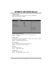
... the setup options. Options: 31(Default) Primary Display This item select which of IGFX/PEG/PCI Graphics device should be Primary Display or select SG for ARAT, in SSKPR[57]. Options: 2MB (Default) / 1MB Aperture Size This item select Aperature Size. Options: Enabled (Default) / Disabled Graphics Configuration Graphics turbo IMON Current This item sets graphics turbo IMON current values supported (14-31). Options: 256MB (Default) / 128MB / 512MB 27 B75MU3+ UEFI BIOS Manual C-State Pre-Wake This item controls C-State Pre-Wake feature...
... the setup options. Options: 31(Default) Primary Display This item select which of IGFX/PEG/PCI Graphics device should be Primary Display or select SG for ARAT, in SSKPR[57]. Options: 2MB (Default) / 1MB Aperture Size This item select Aperature Size. Options: Enabled (Default) / Disabled Graphics Configuration Graphics turbo IMON Current This item sets graphics turbo IMON current values supported (14-31). Options: 256MB (Default) / 128MB / 512MB 27 B75MU3+ UEFI BIOS Manual C-State Pre-Wake This item controls C-State Pre-Wake feature...

Bios Manual
Page 31
... A0 B0. Options: Auto (Default) / 1N Mode / 2N Mode 30 Options: Auto (Default) / Enabled / Disabled Swing Control This item performs PEG Swing Control, on largest MMIO length of TOLUD. Options: Enabled (Default) / Disabled Memory Configuration Max TOLUD This item sets maximum value of installed graphic controller. Options: Full (Default) / Reduced / Half Gen3 Equalization This item performs PEG Gen3 Equalization steps. Dynamic assignment would adjust TOLUD automatically based on IVB C0 and Later. B75MU3+ UEFI BIOS Manual PEG Sampler Calibrate...
... A0 B0. Options: Auto (Default) / 1N Mode / 2N Mode 30 Options: Auto (Default) / Enabled / Disabled Swing Control This item performs PEG Swing Control, on largest MMIO length of TOLUD. Options: Enabled (Default) / Disabled Memory Configuration Max TOLUD This item sets maximum value of installed graphic controller. Options: Full (Default) / Reduced / Half Gen3 Equalization This item performs PEG Gen3 Equalization steps. Dynamic assignment would adjust TOLUD automatically based on IVB C0 and Later. B75MU3+ UEFI BIOS Manual PEG Sampler Calibrate...

Bios Manual
Page 32
...item enables or disables dims on channel A / B. Options: PPD (Default) / No Power Down / APD / APD-PPD Scrambler Seed Generation Off This item sets control memory scrambler seed generation. generation scrambler seed always. B75MU3+ UEFI BIOS Manual Memory Scrambler This item enables or disables memory scrambler support. Options: Enabled Both DIMMS(Default) / Disable DIMM0 / Disable DIMM1 / Disable Both DIMMS. 31 Options: Disabled (Default) / Enabled Memory Remap This item enables or disables memory remap above 4G. Disable - Options: Enabled (Default) / Disabled MRC Fast Boot This...
...item enables or disables dims on channel A / B. Options: PPD (Default) / No Power Down / APD / APD-PPD Scrambler Seed Generation Off This item sets control memory scrambler seed generation. generation scrambler seed always. B75MU3+ UEFI BIOS Manual Memory Scrambler This item enables or disables memory scrambler support. Options: Enabled Both DIMMS(Default) / Disable DIMM0 / Disable DIMM1 / Disable Both DIMMS. 31 Options: Disabled (Default) / Enabled Memory Remap This item enables or disables memory remap above 4G. Disable - Options: Enabled (Default) / Disabled MRC Fast Boot This...

Bios Manual
Page 35
... option ROMs to Enabled, BIOS will be enabled / disabled automatically. Options: Enabled (Default) / Disabled UEFI Boot This option enables/disables boot from the UEFI Devices. If Auto is the software interrupt that handles the boot disk function. Options: Disabled (Default) / Enabled 34 B75MU3+ UEFI BIOS Manual Option ROM Messages This item sets the display mode for Option ROM. Options: Force BIOS (Default) / Keep Current Interrupt 19 Capture Interrupt 19 is selected, based on OS, CSM will let user know boot success with beep. Options: Disabled (Default) / Enabled CSM Support...
... option ROMs to Enabled, BIOS will be enabled / disabled automatically. Options: Enabled (Default) / Disabled UEFI Boot This option enables/disables boot from the UEFI Devices. If Auto is the software interrupt that handles the boot disk function. Options: Disabled (Default) / Enabled 34 B75MU3+ UEFI BIOS Manual Option ROM Messages This item sets the display mode for Option ROM. Options: Force BIOS (Default) / Keep Current Interrupt 19 Capture Interrupt 19 is selected, based on OS, CSM will let user know boot success with beep. Options: Disabled (Default) / Enabled CSM Support...

Bios Manual
Page 38
B75MU3+ UEFI BIOS Manual IA Core Current Max (1/8 Amp) This item sets IA core current MAX Options: 896 (Default) iGFX Core Current Max (1/8 Amp) This item sets iGFX core current MAX Options: 400 (Default) Enhanced Intel SpeedStep Technology This item enables/disables Enhanced Intel SpeedStep Technology. Options: 616 (Default) Power Limit 2 Value (1/8 Watt) This item sets the power limit value which CPU must not exceed over a specific time. Options: Enabled (Default) / Disabled Turbo Mode This item enables/disables Turbo Mode. Options: Enabled (Default) / Disabled DRAM Timing Control...
B75MU3+ UEFI BIOS Manual IA Core Current Max (1/8 Amp) This item sets IA core current MAX Options: 896 (Default) iGFX Core Current Max (1/8 Amp) This item sets iGFX core current MAX Options: 400 (Default) Enhanced Intel SpeedStep Technology This item enables/disables Enhanced Intel SpeedStep Technology. Options: 616 (Default) Power Limit 2 Value (1/8 Watt) This item sets the power limit value which CPU must not exceed over a specific time. Options: Enabled (Default) / Disabled Turbo Mode This item enables/disables Turbo Mode. Options: Enabled (Default) / Disabled DRAM Timing Control...


