Operation Manual
Page 1
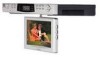
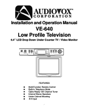
Installation and Operation Manual VE-640 Low Profile Television 6.4" LCD Drop Down Under Counter TV / Video Monitor ON/OFF TV FM/AM A/V TEL TV FM/AM AM PM CH 1 CH 2 CH 3 SEEK SET CH 1 CH 2 CH 3 CH VOL AUDIOVOX FEATURES n Multi-Function Remote Control n Built-In Telephone Mode n Cable Ready 125 Channel Tuner n Internal Stereo Speakers n Under Cabinet Mounting n A/V Input -1-
Installation and Operation Manual VE-640 Low Profile Television 6.4" LCD Drop Down Under Counter TV / Video Monitor ON/OFF TV FM/AM A/V TEL TV FM/AM AM PM CH 1 CH 2 CH 3 SEEK SET CH 1 CH 2 CH 3 CH VOL AUDIOVOX FEATURES n Multi-Function Remote Control n Built-In Telephone Mode n Cable Ready 125 Channel Tuner n Internal Stereo Speakers n Under Cabinet Mounting n A/V Input -1-
Operation Manual
Page 2
... setting. 3) Press the VOLUME up /down buttons (5) to toggle between the hours and the minutes 4) Press the SET button (1) three times to return to enter the alarm mode. 2) Press the SEEK UPv button (3) once. NOTE: The set it is activated. Addendum to the Installation and Operation Manual VE640 Low Profile Television 6.4" LCD Drop Down Under Counter TV / Video Monitor The purpose of this Addendum is to replace the "SETTING...
... setting. 3) Press the VOLUME up /down buttons (5) to toggle between the hours and the minutes 4) Press the SET button (1) three times to return to enter the alarm mode. 2) Press the SEEK UPv button (3) once. NOTE: The set it is activated. Addendum to the Installation and Operation Manual VE640 Low Profile Television 6.4" LCD Drop Down Under Counter TV / Video Monitor The purpose of this Addendum is to replace the "SETTING...
Operation Manual
Page 3
... use extension cords as this can result in a fire or electric shock. Refer all servicing to qualified service personnel. 8) Unplug this TV through openings as opening or removing covers may touch dangerous voltage points or short-circuit parts ...service this video product where it from the outlet and refer servicing to qualified service personnel under the following the operating instructions. IMPORTANT SAFETY INFORMATION 1) Unplug the unit before cleaning. Use a damp cloth for ventilation and are provided for cleaning. 2) Use only Audiovox approved accessories. 3) Do not install...
... use extension cords as this can result in a fire or electric shock. Refer all servicing to qualified service personnel. 8) Unplug this TV through openings as opening or removing covers may touch dangerous voltage points or short-circuit parts ...service this video product where it from the outlet and refer servicing to qualified service personnel under the following the operating instructions. IMPORTANT SAFETY INFORMATION 1) Unplug the unit before cleaning. Use a damp cloth for ventilation and are provided for cleaning. 2) Use only Audiovox approved accessories. 3) Do not install...
Operation Manual
Page 4
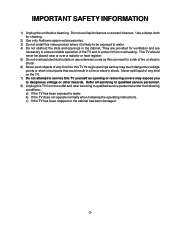
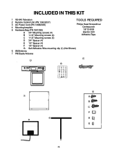
INCLUDED IN THIS KIT 1 VE-640 Television 2 Remote Control Unit (PN 136C2037) 3 AC Power Cord (PN 136B2038) 4 Mounting template 5 Hardware Bag (PN 1501395) A 3/4" Mounting screws (4) B 1-1/4" Mounting screws (4) TOOLS REQUIRED Philips Head Screwdriver Centerpunch 1/8" Drill Bit Electric Drill Adhesive Tape C 1-1/2" Mounting screws (4) D 3/4" Spacer (4) E 1/2" Spacer (4) F 1/4" Spacer (4) G Self Adhesive Wire mounting clip (1) (Not Shown) 6 AM Antenna 7 FM Dipole Antenna 31a 1 2 PWR TEL TTV/VCA VOL MUTE CH ENT CH VOL...
INCLUDED IN THIS KIT 1 VE-640 Television 2 Remote Control Unit (PN 136C2037) 3 AC Power Cord (PN 136B2038) 4 Mounting template 5 Hardware Bag (PN 1501395) A 3/4" Mounting screws (4) B 1-1/4" Mounting screws (4) TOOLS REQUIRED Philips Head Screwdriver Centerpunch 1/8" Drill Bit Electric Drill Adhesive Tape C 1-1/2" Mounting screws (4) D 3/4" Spacer (4) E 1/2" Spacer (4) F 1/4" Spacer (4) G Self Adhesive Wire mounting clip (1) (Not Shown) 6 AM Antenna 7 FM Dipole Antenna 31a 1 2 PWR TEL TTV/VCA VOL MUTE CH ENT CH VOL...
Operation Manual
Page 5
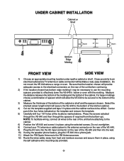
... adequate access to the cabinet. 6) Position the VE-640 and screw it in place using the speaker phone feature, plug the VE-640 into a phone jack. 11) Attach the FM Dipole Antenna to the bottom of the cabinet. 3) Measure the thickness of the bottom of the VE-640. 9) Plug the AC wire into the wall. 10) If using the selected screws. Place the screws...
... adequate access to the cabinet. 6) Position the VE-640 and screw it in place using the speaker phone feature, plug the VE-640 into a phone jack. 11) Attach the FM Dipole Antenna to the bottom of the cabinet. 3) Measure the thickness of the bottom of the VE-640. 9) Plug the AC wire into the wall. 10) If using the selected screws. Place the screws...
Operation Manual
Page 6
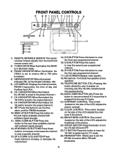
... illuminated indicates- FRONT PANEL CONTROLS 1) REMOTE INFRARED SENSOR-This sensor receives infrared signals from the hand held remote control unit. 2) TV INDICATOR-When illuminated, the VE640 is in television mode. 3) FM/AM INDICATOR-When illuminated, the VE640 is set to view an external A/V source that is tuned to the preset channel 3. 9) SET-Press this button to set the VE-640 to view the first user programmed channel. 17) LCD-SCREEN-Displays video signals. 18) Microphone- Allows user to set the time, alarm, and the...
... illuminated indicates- FRONT PANEL CONTROLS 1) REMOTE INFRARED SENSOR-This sensor receives infrared signals from the hand held remote control unit. 2) TV INDICATOR-When illuminated, the VE640 is in television mode. 3) FM/AM INDICATOR-When illuminated, the VE640 is set to view an external A/V source that is tuned to the preset channel 3. 9) SET-Press this button to set the VE-640 to view the first user programmed channel. 17) LCD-SCREEN-Displays video signals. 18) Microphone- Allows user to set the time, alarm, and the...
Operation Manual
Page 7
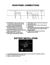
... until it clicks. -7- REAR PANEL CONNECTIONS AM-ANT. AUDIO-IN VIDEO-IN 1) FM ANTENNA- Allows the VE-640 to be connected to an external antenna for the external A/V source. BATTERY INSTALLATION 1) Turn the Remote Control face down. output from connected to a 75 ohm external coaxial antenna. audio output from external A/V source. FM-ANT. Allows the VE-640 to be connected 7) AM ANTENNA-Allows the VE-640 to be 5) VIDEO INPUT-Connect to the video output from external A/V source. 8) POWER INPUT-Connect to AC line cord 4) AUDIO INPUT-LEFT-Connect to Telco jack...
... until it clicks. -7- REAR PANEL CONNECTIONS AM-ANT. AUDIO-IN VIDEO-IN 1) FM ANTENNA- Allows the VE-640 to be connected to an external antenna for the external A/V source. BATTERY INSTALLATION 1) Turn the Remote Control face down. output from connected to a 75 ohm external coaxial antenna. audio output from external A/V source. FM-ANT. Allows the VE-640 to be connected 7) AM ANTENNA-Allows the VE-640 to be 5) VIDEO INPUT-Connect to the video output from external A/V source. 8) POWER INPUT-Connect to AC line cord 4) AUDIO INPUT-LEFT-Connect to Telco jack...
Operation Manual
Page 8
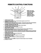
...-640. SEEK BUTTONS (SEEK) Tunes the VE-640 to increase or decrease the volume. 5. NUMERICAL BUTTONS (1- 9, 0) Use these buttons to advance to the next higher or lower channel. 4. CHANNEL UP/DOWN BUTTONS (CH) Use these buttons to turn the TV on oven or range). 7 8 9 0 1. The mute feature may also be displayed on front panel. FM/AM BUTTON (FM/AM) Each time this button is carried out using the 0-9 keys. 3. REMOTE CONTROL...
...-640. SEEK BUTTONS (SEEK) Tunes the VE-640 to increase or decrease the volume. 5. NUMERICAL BUTTONS (1- 9, 0) Use these buttons to advance to the next higher or lower channel. 4. CHANNEL UP/DOWN BUTTONS (CH) Use these buttons to turn the TV on oven or range). 7 8 9 0 1. The mute feature may also be displayed on front panel. FM/AM BUTTON (FM/AM) Each time this button is carried out using the 0-9 keys. 3. REMOTE CONTROL...
Operation Manual
Page 9
... SET button three times to return to the time display on the LCD panel. Remember to Broadcast TV it off. When set to turn it receives CH2-CH69. NOTE: Most cable companies broadcast in use . When set to select the cable mode (STD/IRC/HRC). -9- POSITIONING THE SCREEN Pivot the screen forward until a comfortable viewing angle is reached, press the SET button to confirm. 4) Press the channel 1 button to one of a converter box...
... SET button three times to return to the time display on the LCD panel. Remember to Broadcast TV it off. When set to turn it receives CH2-CH69. NOTE: Most cable companies broadcast in use . When set to select the cable mode (STD/IRC/HRC). -9- POSITIONING THE SCREEN Pivot the screen forward until a comfortable viewing angle is reached, press the SET button to confirm. 4) Press the channel 1 button to one of a converter box...

Operation Manual
Page 10
... infrared LED on screen Solution Verify Tuner setting matches Antenna / Cable broadcast system. Problem Poor Reception Remote control will be blank. Verify Tuner setting matches Antenna / Cable broadcast system.Try other system types with the TV/CATV BUTTON of the remote control batteries. Press the TV button to confirm selection. Verify that the sensor on the VE-640 is not obstructed. If unit is in AUX MODE and there is no video signal...
... infrared LED on screen Solution Verify Tuner setting matches Antenna / Cable broadcast system. Problem Poor Reception Remote control will be blank. Verify Tuner setting matches Antenna / Cable broadcast system.Try other system types with the TV/CATV BUTTON of the remote control batteries. Press the TV button to confirm selection. Verify that the sensor on the VE-640 is not obstructed. If unit is in AUX MODE and there is no video signal...
Operation Manual
Page 11
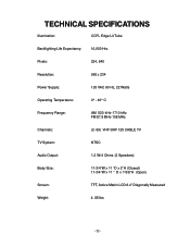
TECHNICAL SPECIFICATIONS Illumination: CCFL Edge Lit Tube Backlighting Life Expectancy: 10,000 Hrs. Pixels: 224, 640 Resolution: 960 x 234 Power Supply: 120 VAC 60 Hz, 22 Watts Operating Temperature: 0° - 40° C Frequency Range: AM 520 kHz-1710 kHz FM 87.5 MHz-108 MHz Channels: (2- 69) VHF/UHF 125 CABLE TV TV System: NTSC Audio Output: 1.2 W/4 Ohms (2 Speakers) Body Size: 11-3/4"W x 11 "D x 2"H (Closed) 11-3/4"W x 11 " D x 7-5/8"H (Open) Screen: TFT, Active Matrix LCD 6.4" Diagonally Measured Weight: 4. 85 lbs -11-
TECHNICAL SPECIFICATIONS Illumination: CCFL Edge Lit Tube Backlighting Life Expectancy: 10,000 Hrs. Pixels: 224, 640 Resolution: 960 x 234 Power Supply: 120 VAC 60 Hz, 22 Watts Operating Temperature: 0° - 40° C Frequency Range: AM 520 kHz-1710 kHz FM 87.5 MHz-108 MHz Channels: (2- 69) VHF/UHF 125 CABLE TV TV System: NTSC Audio Output: 1.2 W/4 Ohms (2 Speakers) Body Size: 11-3/4"W x 11 "D x 2"H (Closed) 11-3/4"W x 11 " D x 7-5/8"H (Open) Screen: TFT, Active Matrix LCD 6.4" Diagonally Measured Weight: 4. 85 lbs -11-
Operation Manual
Page 12
... sale), specification of defect(s), transportation prepaid, to the Company at the Company's option) without charge for installation, removal or reinstallation of the product, or to damage to tapes, discs, speakers, accessories, or electrical systems. This Warranty does not apply to assume for the Company any liability other rights which , in lieu of the factory serial number/bar code label(s).
... sale), specification of defect(s), transportation prepaid, to the Company at the Company's option) without charge for installation, removal or reinstallation of the product, or to damage to tapes, discs, speakers, accessories, or electrical systems. This Warranty does not apply to assume for the Company any liability other rights which , in lieu of the factory serial number/bar code label(s).


