User Manual
Page 3
Table of Contents Introduction 5 Features 6 Safety and Care Information 7 What's in the Box 9 Starmate 8 Functions 10 PowerConnect Vehicle Dock 11 Vehicle Installation 13 Step 1: Choose a Location for Your Radio 14 Step 2: Install the Vent or Dash Mount . 16 Step 3: Mount the Magnetic Mount Antenna 20 Step 4: ...
Table of Contents Introduction 5 Features 6 Safety and Care Information 7 What's in the Box 9 Starmate 8 Functions 10 PowerConnect Vehicle Dock 11 Vehicle Installation 13 Step 1: Choose a Location for Your Radio 14 Step 2: Install the Vent or Dash Mount . 16 Step 3: Mount the Magnetic Mount Antenna 20 Step 4: ...
User Manual
Page 6
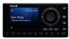
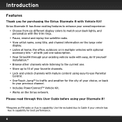
...• Browse other channels while listening to the current one. • Store up to 10 of your choice, or back to your vehicle has Aux In capability for purchasing the Sirius Starmate 8 with optional accessory kits - Use the included Aux In Cable if your previous channel.... • Includes PowerConnect™ Vehicle Kit. • Works on the large color display. • Listen at home, the office, outdoors or in multiple vehicles with Vehicle Kit! Sirius Starmate 8 has these exciting features to enhance your overall experience: ...
...• Browse other channels while listening to the current one. • Store up to 10 of your choice, or back to your vehicle has Aux In capability for purchasing the Sirius Starmate 8 with optional accessory kits - Use the included Aux In Cable if your previous channel.... • Includes PowerConnect™ Vehicle Kit. • Works on the large color display. • Listen at home, the office, outdoors or in multiple vehicles with Vehicle Kit! Sirius Starmate 8 has these exciting features to enhance your overall experience: ...

User Manual
Page 7
... period of any foreign matter spill into device. • Do not store in dusty areas. • Do not expose to chemicals such as to allow a vehicle to excessive pressure. • If the LCD screen is your responsibility to determine if you have no liability for damage or injury resulting from the...
... period of any foreign matter spill into device. • Do not store in dusty areas. • Do not expose to chemicals such as to allow a vehicle to excessive pressure. • If the LCD screen is your responsibility to determine if you have no liability for damage or injury resulting from the...

User Manual
Page 8
... wheel. Not doing so could result in personal injury, death, and/or damage to your device, accessories, and/or to your vehicle in a safe location before beginning installation. • This product contains chemicals known to the State of California to cause cancer and ...birth defects or other property. • Vehicle installation, service activation, and Radio configuration functions should be performed while driving. Some multi-outlet adapters can prevent the PowerConnect feature from working...
... wheel. Not doing so could result in personal injury, death, and/or damage to your device, accessories, and/or to your vehicle in a safe location before beginning installation. • This product contains chemicals known to the State of California to cause cancer and ...birth defects or other property. • Vehicle installation, service activation, and Radio configuration functions should be performed while driving. Some multi-outlet adapters can prevent the PowerConnect feature from working...

User Manual
Page 9
What's in the Box? menu FM jump 1 2 3 4 5 6 7 8 9 0 direct Starmate 8 Radio PowerConnect Vehicle Dock Dash Mount Aux In Cable Trim Rings Trim Ring Removal Tool Vent Mount and Extended Vent Clamps PowerConnect Power Adapter Magnetic Mount Antenna & Tail Antenna & Dash Mount Screws Alcohol Preparation Pads 9
What's in the Box? menu FM jump 1 2 3 4 5 6 7 8 9 0 direct Starmate 8 Radio PowerConnect Vehicle Dock Dash Mount Aux In Cable Trim Rings Trim Ring Removal Tool Vent Mount and Extended Vent Clamps PowerConnect Power Adapter Magnetic Mount Antenna & Tail Antenna & Dash Mount Screws Alcohol Preparation Pads 9
User Manual
Page 11
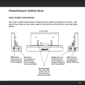
AUDIO (Green) Connection for Aux In Cable or Cassette Adapter (sold separately). PowerConnect Vehicle Dock Color-Coded Connections The color-coded PowerConnect Vehicle Dock makes it simple to secure the Radio. 11 Docking Rails Fits into slots on the dock to see what goes where. Front View PWR ...
AUDIO (Green) Connection for Aux In Cable or Cassette Adapter (sold separately). PowerConnect Vehicle Dock Color-Coded Connections The color-coded PowerConnect Vehicle Dock makes it simple to secure the Radio. 11 Docking Rails Fits into slots on the dock to see what goes where. Front View PWR ...

User Manual
Page 14
... the air bag. menu FM jump 1 2 3 4 5 6 7 8 9 0 direct menu FM jump 1 2 3 4 5 6 7 8 9 0 direct A. 14 Vehicle Installation WARNING! Several examples of the display screen. DO NOT attempt to install Starmate 8 while driving. The location should be easily accessible and provide good ... Option 2 A. Step 1: Choose a Location for Your Radio When installing Starmate 8 in your vehicle, choose a location where it will be in direct sunlight, which will not block your vehicle in a vehicle are shown: A is the on dash method using the Dash Mount, and B is the ...
... the air bag. menu FM jump 1 2 3 4 5 6 7 8 9 0 direct menu FM jump 1 2 3 4 5 6 7 8 9 0 direct A. 14 Vehicle Installation WARNING! Several examples of the display screen. DO NOT attempt to install Starmate 8 while driving. The location should be easily accessible and provide good ... Option 2 A. Step 1: Choose a Location for Your Radio When installing Starmate 8 in your vehicle, choose a location where it will be in direct sunlight, which will not block your vehicle in a vehicle are shown: A is the on dash method using the Dash Mount, and B is the ...

User Manual
Page 16
... "Step 1: Choose a Location for the Dash Mount. If it's not at least 60°F (15°C) during installation. Vehicle Installation Step 2: Install the Vent or Dash Mount Depending on leather surfaces (contact your vehicle dealer if you can either choose to use the Dash Mount or the Vent Mount. Do not install... this mount on your vehicle to bring the temperature up to 60°F. 1 Locate a flat surface for Your Radio" on page 14: • Option 1 & Option 3 should be oriented as II. 3 ...
... "Step 1: Choose a Location for the Dash Mount. If it's not at least 60°F (15°C) during installation. Vehicle Installation Step 2: Install the Vent or Dash Mount Depending on leather surfaces (contact your vehicle dealer if you can either choose to use the Dash Mount or the Vent Mount. Do not install... this mount on your vehicle to bring the temperature up to 60°F. 1 Locate a flat surface for Your Radio" on page 14: • Option 1 & Option 3 should be oriented as II. 3 ...

User Manual
Page 17
Position, press, and hold the Dash Mount and PowerConnect Vehicle Dock in different directions. Adjust as necessary for several minutes will help soften the adhesive. 17 To remove, carefully lift the adhesive pad with a hair ...dryer for your fingers or a spoon. When the orientation is correct, tighten the knob. Warming the pad with your particular vehicle. Knob Adhesive Foot Dock Mounting Plate TIP! IMPORTANT! The best adhesion occurs after 24 hours. 6 The dock mounting plate can be tilted in place for...
Position, press, and hold the Dash Mount and PowerConnect Vehicle Dock in different directions. Adjust as necessary for several minutes will help soften the adhesive. 17 To remove, carefully lift the adhesive pad with a hair ...dryer for your fingers or a spoon. When the orientation is correct, tighten the knob. Warming the pad with your particular vehicle. Knob Adhesive Foot Dock Mounting Plate TIP! IMPORTANT! The best adhesion occurs after 24 hours. 6 The dock mounting plate can be tilted in place for...
User Manual
Page 18
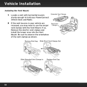
Remove End Cap Slide Short Vent Clamps Out Slide Extended Vent Clamps In Replace End Cap 18 Be sure to use the longer Clamps vent clamps with the Vent Mount. Vehicle Installation Installing the Vent Mount: 1 Locate a vent with horizontal louvers Extended Vent Clamps sturdy enough to hold your PowerConnect Vehicle Dock and Radio. 2 If the vent louvers in your vehicle are Short Vent recessed, you may need to observe the orientation of the vent clamps as shown. If so, Remove the shorter vent clamps and install the longer ones into the Vent Mount.
Remove End Cap Slide Short Vent Clamps Out Slide Extended Vent Clamps In Replace End Cap 18 Be sure to use the longer Clamps vent clamps with the Vent Mount. Vehicle Installation Installing the Vent Mount: 1 Locate a vent with horizontal louvers Extended Vent Clamps sturdy enough to hold your PowerConnect Vehicle Dock and Radio. 2 If the vent louvers in your vehicle are Short Vent recessed, you may need to observe the orientation of the vent clamps as shown. If so, Remove the shorter vent clamps and install the longer ones into the Vent Mount.

User Manual
Page 19
3 Attach the Vent Mount to the PowerConnect Vehicle Dock using the provided screws. 4 Push the Vent Mount onto the vehicle vent as shown (1) until disengaged from the rear of the Vent Mount by repositioning the foot to a different adjustment hole (3). PUSH 1 2 3 Dash Dash HOOKED Dash Vent FOOT Louver Vent TILT ADJUSTMENT HOLES Vent To remove the Vent Mount, push the mount into the vent. Then lift up until it hooks on the rear of the vent louver (2). 5 Rest the foot against the bottom of the vent (2), and adjust the tilt of the vent louver, and remove the Vent Mount. 19
3 Attach the Vent Mount to the PowerConnect Vehicle Dock using the provided screws. 4 Push the Vent Mount onto the vehicle vent as shown (1) until disengaged from the rear of the Vent Mount by repositioning the foot to a different adjustment hole (3). PUSH 1 2 3 Dash Dash HOOKED Dash Vent FOOT Louver Vent TILT ADJUSTMENT HOLES Vent To remove the Vent Mount, push the mount into the vent. Then lift up until it hooks on the rear of the vent louver (2). 5 Rest the foot against the bottom of the vent (2), and adjust the tilt of the vent louver, and remove the Vent Mount. 19

User Manual
Page 20
Pay particular attention to any accessories that you may have like luggage racks and how frequently you may use them. To install the Magnetic Mount Antenna: 1 Choose the best location for your antenna considering your vehicle, but will not damage the vehicle. Vehicle Installation Step 3: Mount the Magnetic Mount Antenna The Magnetic Mount Antenna contains a strong magnet which will stick to any metal part of your own personal situation. Magnet Sedan/Coupe: We recommend mounting the antenna above either the front windshield or the back window as shown. 20
Pay particular attention to any accessories that you may have like luggage racks and how frequently you may use them. To install the Magnetic Mount Antenna: 1 Choose the best location for your antenna considering your vehicle, but will not damage the vehicle. Vehicle Installation Step 3: Mount the Magnetic Mount Antenna The Magnetic Mount Antenna contains a strong magnet which will stick to any metal part of your own personal situation. Magnet Sedan/Coupe: We recommend mounting the antenna above either the front windshield or the back window as shown. 20

User Manual
Page 22
.... During this period, avoid car washes and other contact with the antenna and the Rubber Tail. 22 Vehicle Installation 2 Attach the Rubber Tail to the antenna and press the antenna cable into place on the vehicle. 5 Continue to position the antenna the correct distance from the adhesive strips and press the Rubber...
.... During this period, avoid car washes and other contact with the antenna and the Rubber Tail. 22 Vehicle Installation 2 Attach the Rubber Tail to the antenna and press the antenna cable into place on the vehicle. 5 Continue to position the antenna the correct distance from the adhesive strips and press the Rubber...

User Manual
Page 23
TIP! Mount the antenna on the roof (for most vehicles) or trunk (for convertibles) where it has a clear view of the sky in all directions. 23
TIP! Mount the antenna on the roof (for most vehicles) or trunk (for convertibles) where it has a clear view of the sky in all directions. 23

User Manual
Page 24
TIP! CAUTION! Mount the antenna on the roof where it has at least 3 inches of the roof. Vehicle Installation 3" TIP! Use the supplied Rubber Tail to cover and protect the antenna cable. Don't mount the antenna closer than 3 inches from the edge of clear space around it. Use the supplied Rubber Tail as a guide for judging proper length and correct positioning. 24
TIP! CAUTION! Mount the antenna on the roof where it has at least 3 inches of the roof. Vehicle Installation 3" TIP! Use the supplied Rubber Tail to cover and protect the antenna cable. Don't mount the antenna closer than 3 inches from the edge of clear space around it. Use the supplied Rubber Tail as a guide for judging proper length and correct positioning. 24

User Manual
Page 25
CAUTION! Adjust the rack so it's further away from the antenna or move the antenna closer to a roof rack. Don't mount the antenna on the dashboard. Don't mount the antenna close to the center of the vehicle's front, back or side pillars. CAUTION! CAUTION! Don't mount the antenna inside the vehicle, for example, on any of the roof. 25
CAUTION! Adjust the rack so it's further away from the antenna or move the antenna closer to a roof rack. Don't mount the antenna on the dashboard. Don't mount the antenna close to the center of the vehicle's front, back or side pillars. CAUTION! CAUTION! Don't mount the antenna inside the vehicle, for example, on any of the roof. 25

User Manual
Page 26
Always be careful to include enough slack in your cable to secure cables in the trim. 26 Vehicle Installation CAUTION! TIP! Use things typically found around the home, like electrical tape, to accommodate open doors or trunk lids. Don't mount the Magnetic Mount Antenna close to another antenna. Hide any excess cable in areas so that hinges do not pinch the cable with the door. Mount it at least 3 inches away.
Always be careful to include enough slack in your cable to secure cables in the trim. 26 Vehicle Installation CAUTION! TIP! Use things typically found around the home, like electrical tape, to accommodate open doors or trunk lids. Don't mount the Magnetic Mount Antenna close to another antenna. Hide any excess cable in areas so that hinges do not pinch the cable with the door. Mount it at least 3 inches away.

User Manual
Page 27
Then route your specific type of vehicle. Use a blunt plastic putty knife, a credit card, a plastic knife, or a similar blunt tool to route and hide the antenna cable. Step 4: Route the Magnetic Mount Antenna Cable Before you begin routing the antenna cable, read these general instructions for your antenna cable according to the instructions which follow for how to lift the rubber window moulding Tuck the cable under the moulding around the window Feed cable under rubber moulding around window 27
Then route your specific type of vehicle. Use a blunt plastic putty knife, a credit card, a plastic knife, or a similar blunt tool to route and hide the antenna cable. Step 4: Route the Magnetic Mount Antenna Cable Before you begin routing the antenna cable, read these general instructions for your antenna cable according to the instructions which follow for how to lift the rubber window moulding Tuck the cable under the moulding around the window Feed cable under rubber moulding around window 27

User Manual
Page 28
Vehicle Installation Route cable out from trunk opening Tuck cable into weatherstripping around trunk opening Avoid sharp bends by running cable through weatherstripping for several inches to avoid sharp bends Pull cable out of weatherstripping and route through weatherstripping several inches Pull weatherstripping from under rear windshield moulding and tuck into weatherstripping around trunk opening 28 Route cable through trunk to cabin Route cable out of window moulding and into weatherstripping.
Vehicle Installation Route cable out from trunk opening Tuck cable into weatherstripping around trunk opening Avoid sharp bends by running cable through weatherstripping for several inches to avoid sharp bends Pull cable out of weatherstripping and route through weatherstripping several inches Pull weatherstripping from under rear windshield moulding and tuck into weatherstripping around trunk opening 28 Route cable through trunk to cabin Route cable out of window moulding and into weatherstripping.

User Manual
Page 30
Vehicle Installation Use a blunt plastic putty knife or similar blunt tool trim and tuck cable under interior trim, into cabin and towards front of vehicle 30 Continue towards front of vehicle Route cable under trim or upholstery Continue routing cable under trim or carpet towards front of vehicle Route cable from trunk under trim.
Vehicle Installation Use a blunt plastic putty knife or similar blunt tool trim and tuck cable under interior trim, into cabin and towards front of vehicle 30 Continue towards front of vehicle Route cable under trim or upholstery Continue routing cable under trim or carpet towards front of vehicle Route cable from trunk under trim.
