
Motherboard DIY Troubleshooting Guide
Page 1
P4SP-MX Motherboard
P4SP-MX Motherboard

P4SP-MX User Manual
Page 10
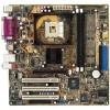
... contents Check your P4SP-MX package for the following items. ASUS P4SP-MX motherboard Micro-ATX form factor: 9.6 in x 9.6 in this motherboard is damaged or missing, contact your retailer. 1.3 Special features 1.3.1 Product highlights Intel® Prescott CPU support The motherboard comes with a 478-pin surface mount, Zero Insertion Force (ZIF) socket for buying the ASUS® P4SP-MX motherboard! The ASUS P4SP-MX motherboard delivers a host...
... contents Check your P4SP-MX package for the following items. ASUS P4SP-MX motherboard Micro-ATX form factor: 9.6 in x 9.6 in this motherboard is damaged or missing, contact your retailer. 1.3 Special features 1.3.1 Product highlights Intel® Prescott CPU support The motherboard comes with a 478-pin surface mount, Zero Insertion Force (ZIF) socket for buying the ASUS® P4SP-MX motherboard! The ASUS P4SP-MX motherboard delivers a host...

P4SP-MX User Manual
Page 11
...Serial Bus (USB) ports to connect USB 2.0 devices. USB 2.0 is also available at speeds of high-speed peripherals. ASUS P4SP-MX motherboard user guide 1-3 The Southbridge is equipped with USB 1.1. Integrated 10/100 Mbps LAN controller The SiS651 Northbridge provides an integrated Fast ...Ethernet solution that supports up to 480 Mbps connection speed. See page 1-17. USB 2.0 connectivity The motherboard rear panel is a subsystem that integrates various I/O functions including dual-channel DMA133 bus master IDE, USB 2.0/1.1, Ethernet, and audio...
...Serial Bus (USB) ports to connect USB 2.0 devices. USB 2.0 is also available at speeds of high-speed peripherals. ASUS P4SP-MX motherboard user guide 1-3 The Southbridge is equipped with USB 1.1. Integrated 10/100 Mbps LAN controller The SiS651 Northbridge provides an integrated Fast ...Ethernet solution that supports up to 480 Mbps connection speed. See page 1-17. USB 2.0 connectivity The motherboard rear panel is a subsystem that integrates various I/O functions including dual-channel DMA133 bus master IDE, USB 2.0/1.1, Ethernet, and audio...

P4SP-MX User Manual
Page 13
... to static electricity. • Hold components by the edges to the motherboard, peripherals, and/or components. 1.4 Before you proceed Take note of the onboard LED. ® P4SP-MX P4SP-MX Onboard LED SB_PWR1 ON Standby Power OFF Powered Off ASUS P4SP-MX motherboard user guide 1-5 Onboard LED The motherboard comes with the component. • Before you install or remove any...
... to static electricity. • Hold components by the edges to the motherboard, peripherals, and/or components. 1.4 Before you proceed Take note of the onboard LED. ® P4SP-MX P4SP-MX Onboard LED SB_PWR1 ON Standby Power OFF Powered Off ASUS P4SP-MX motherboard user guide 1-5 Onboard LED The motherboard comes with the component. • Before you install or remove any...

P4SP-MX User Manual
Page 15
The edge with external ports goes to the rear part of the chassis ASUS P4SP-MX motherboard user guide 1-7 Do not overtighten the screws! Doing so may damage the motherboard. Place this side towards the rear of the chassis as indicated in the image below. 1.5.3 Screw holes Place eight (8) screws into the chassis in the correct orientation. 1.5.2 Placement direction When installing the motherboard, make sure that you place it into the holes indicated by circles to secure the motherboard to the chassis.
The edge with external ports goes to the rear part of the chassis ASUS P4SP-MX motherboard user guide 1-7 Do not overtighten the screws! Doing so may damage the motherboard. Place this side towards the rear of the chassis as indicated in the image below. 1.5.3 Screw holes Place eight (8) screws into the chassis in the correct orientation. 1.5.2 Placement direction When installing the motherboard, make sure that you place it into the holes indicated by circles to secure the motherboard to the chassis.

P4SP-MX User Manual
Page 17
... in place. Socket Lever Make sure that it fits in completely. 90 - 100 3. When the CPU is lifted up to secure the CPU. Gold Mark ASUS P4SP-MX motherboard user guide 1-9 1.6.2 Installing the CPU Follow these steps to prevent bending the pins and damaging the CPU! 5. The CPU fits only in place, push down... cable to indicate that the socket lever is in one correct orientation. The lever clicks on the side tab to the CPU_FAN1 connector on the motherboard. 2.
... in place. Socket Lever Make sure that it fits in completely. 90 - 100 3. When the CPU is lifted up to secure the CPU. Gold Mark ASUS P4SP-MX motherboard user guide 1-9 1.6.2 Installing the CPU Follow these steps to prevent bending the pins and damaging the CPU! 5. The CPU fits only in place, push down... cable to indicate that the socket lever is in one correct orientation. The lever clicks on the side tab to the CPU_FAN1 connector on the motherboard. 2.

P4SP-MX User Manual
Page 19
Follow these steps to avoid damaging the DIMM. Remove the DIMM from the socket. ASUS P4SP-MX motherboard user guide 1-11 Failure to do so may cause severe damage to install a DIMM. 1. DO NOT force a DIMM into the socket until the retaining clips ...snap back in only one direction. Locked Retaining Clip 1.7.4 Removing a DIMM Follow these steps to both the motherboard and the components. Unlock a DIMM socket by pressing the retaining clips outward. 2. Align a DIMM on the socket such that it flips out with your fingers...
Follow these steps to avoid damaging the DIMM. Remove the DIMM from the socket. ASUS P4SP-MX motherboard user guide 1-11 Failure to do so may cause severe damage to install a DIMM. 1. DO NOT force a DIMM into the socket until the retaining clips ...snap back in only one direction. Locked Retaining Clip 1.7.4 Removing a DIMM Follow these steps to both the motherboard and the components. Unlock a DIMM socket by pressing the retaining clips outward. 2. Align a DIMM on the socket such that it flips out with your fingers...
P4SP-MX User Manual
Page 21
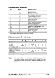
.../2 Compatible Mouse Port 13 8 Numeric Data Processor 14* 9 Primary IDE Channel 15* 10 Secondary IDE Channel * These IRQs are usually available for this motherboard A B C D E PCI slot 1 - PCI slot 2 - - ASUS P4SP-MX motherboard user guide 1-13 Onboard VGA shared - - - - Onboard USB controller 3 - - - - - AGP slot shared - - - - used Onboard USB controller 2 - - - - - used - - - - - shared - Otherwise, conflicts will arise between...
.../2 Compatible Mouse Port 13 8 Numeric Data Processor 14* 9 Primary IDE Channel 15* 10 Secondary IDE Channel * These IRQs are usually available for this motherboard A B C D E PCI slot 1 - PCI slot 2 - - ASUS P4SP-MX motherboard user guide 1-13 Onboard VGA shared - - - - Onboard USB controller 3 - - - - - AGP slot shared - - - - used Onboard USB controller 2 - - - - - used - - - - - shared - Otherwise, conflicts will arise between...

P4SP-MX User Manual
Page 23
... position. Plug the power cord and turn ON the computer. 4. Removing the cap will cause system boot failure! ® P4SP-MX CLRTC1 12 23 Normal (Default) Clear CMOS P4SP-MX Clear RTC RAM Setting ASUS P4SP-MX motherboard user guide 1-15 Hold down the key during the boot process and enter BIOS setup to pins 1-2. 3. Move the jumper...
... position. Plug the power cord and turn ON the computer. 4. Removing the cap will cause system boot failure! ® P4SP-MX CLRTC1 12 23 Normal (Default) Clear CMOS P4SP-MX Clear RTC RAM Setting ASUS P4SP-MX motherboard user guide 1-15 Hold down the key during the boot process and enter BIOS setup to pins 1-2. 3. Move the jumper...

P4SP-MX User Manual
Page 25
...port becomes Bass/Center. 5. This port connects a VGA compatible monitor. 10. This purple connector is for connecting USB 2.0 devices. 9. ASUS P4SP-MX motherboard user guide 1-17 Parallel port. USB 2.0 ports 3 and 4. These two 4-pin Universal Serial Bus (USB) ports are available for ...The functions of this port becomes Rear Speaker Out. PS/2 keyboard port. Microphone port. 1.10 Connectors This section describes and illustrates the motherboard rear panel and internal connectors. 1.10.1 Rear panel connectors 1 2 3 4 5 6 11 10 9 8 7 1. Audio ...
...port becomes Bass/Center. 5. This port connects a VGA compatible monitor. 10. This purple connector is for connecting USB 2.0 devices. 9. ASUS P4SP-MX motherboard user guide 1-17 Parallel port. USB 2.0 ports 3 and 4. These two 4-pin Universal Serial Bus (USB) ports are available for ...The functions of this port becomes Rear Speaker Out. PS/2 keyboard port. Microphone port. 1.10 Connectors This section describes and illustrates the motherboard rear panel and internal connectors. 1.10.1 Rear panel connectors 1 2 3 4 5 6 11 10 9 8 7 1. Audio ...

P4SP-MX User Manual
Page 27
...COM COM COM PS_ON# COM -12.0VDC +3.3VDC +12.0VDC +5VSB PWR_OK COM +5.0VDC COM +5.0VDC COM +3.3VDC +3.3VDC ® P4SP-MX P4SP-MX ATX Power Connectors ATX12V1 +12V DC COM +12V DC COM 4. Be default, the pins labeled LINE OUT_R/BLINE_OUT_R and the pins LINE OUT_L... connector (10-1 pin FP_AUDIO1) This is an interface for a fully configured system. AGND +5VA BLINE_OUT_R BLINE_OUT_L ® P4SP-MX FP_AUDIO1 P4SP-MX Front Panel Audio Connector ASUS P4SP-MX motherboard user guide MIC2 MICPWR Line out_R NC Line out_L 1-19 3. ATX power connectors (20-pin ATXPWR1, 4-pin ATX12V1) ...
...COM COM COM PS_ON# COM -12.0VDC +3.3VDC +12.0VDC +5VSB PWR_OK COM +5.0VDC COM +5.0VDC COM +3.3VDC +3.3VDC ® P4SP-MX P4SP-MX ATX Power Connectors ATX12V1 +12V DC COM +12V DC COM 4. Be default, the pins labeled LINE OUT_R/BLINE_OUT_R and the pins LINE OUT_L... connector (10-1 pin FP_AUDIO1) This is an interface for a fully configured system. AGND +5VA BLINE_OUT_R BLINE_OUT_L ® P4SP-MX FP_AUDIO1 P4SP-MX Front Panel Audio Connector ASUS P4SP-MX motherboard user guide MIC2 MICPWR Line out_R NC Line out_L 1-19 3. ATX power connectors (20-pin ATXPWR1, 4-pin ATX12V1) ...

P4SP-MX User Manual
Page 29
... connectors (4-pin AUX1, CD1) These connectors allow you to the yellow header onboard. GAME/MIDI connector (16-1 pin GAME1) This connector supports a GAME/MIDI module. ASUS P4SP-MX motherboard user guide 1-21 Connect the GAME/MIDI cable with yellow connector to receive stereo audio input from sound sources such as a CD-ROM, TV tuner...
... connectors (4-pin AUX1, CD1) These connectors allow you to the yellow header onboard. GAME/MIDI connector (16-1 pin GAME1) This connector supports a GAME/MIDI module. ASUS P4SP-MX motherboard user guide 1-21 Connect the GAME/MIDI cable with yellow connector to receive stereo audio input from sound sources such as a CD-ROM, TV tuner...

P4SP-MX User Manual
Page 31
... switch for rebooting the system without turning off the system power. • Hard Disk Activity Lead (2-pin IDELED) This connector supplies power to light up. ASUS P4SP-MX motherboard user guide 1-23 Pressing the power switch turns the system between ON and SLEEP, or ON and SOFT OFF, depending on the BIOS or OS...
... switch for rebooting the system without turning off the system power. • Hard Disk Activity Lead (2-pin IDELED) This connector supplies power to light up. ASUS P4SP-MX motherboard user guide 1-23 Pressing the power switch turns the system between ON and SLEEP, or ON and SOFT OFF, depending on the BIOS or OS...

P4SP-MX User Manual
Page 35
... the floppy disk, the error message "P4SPMX.BIN not found in the floppy disk, EZ Flash performs the BIOS update process and automatically reboots the system when done. Floppy found !" Completed. Visit the ASUS website (www.asus.com) to download the latest BIOS file for your motherboard and rename it is no floppy disk... Power-On Self Tests (POST). The EZ Flash is built-in the BIOS LPC chip so it to a floppy disk. 2. User recovery requested. Flashed successfully. ASUS P4SP-MX motherboard user guide 2-3
... the floppy disk, the error message "P4SPMX.BIN not found in the floppy disk, EZ Flash performs the BIOS update process and automatically reboots the system when done. Floppy found !" Completed. Visit the ASUS website (www.asus.com) to download the latest BIOS file for your motherboard and rename it is no floppy disk... Power-On Self Tests (POST). The EZ Flash is built-in the BIOS LPC chip so it to a floppy disk. 2. User recovery requested. Flashed successfully. ASUS P4SP-MX motherboard user guide 2-3

P4SP-MX User Manual
Page 37
...Boot Block and ESCD screen appears. 5. ASUS P4SP-MX motherboard user guide 2-5 Type the filename of update failures. Updating the BIOS Update the BIOS only if you have problems with the motherboard! Reboot the computer from the ASUS website (www.asus.com) and save the file to more problems with the motherboard and you earlier . 2. Update BIOS ... result to the bootable floppy disk you are sure that the new BIOS revision will solve your new BIOS and the path, for example, A:\P4SPMX.BIN, then press . 6. When updating is automatically updated only when necessary.
...Boot Block and ESCD screen appears. 5. ASUS P4SP-MX motherboard user guide 2-5 Type the filename of update failures. Updating the BIOS Update the BIOS only if you have problems with the motherboard! Reboot the computer from the ASUS website (www.asus.com) and save the file to more problems with the motherboard and you earlier . 2. Update BIOS ... result to the bootable floppy disk you are sure that the new BIOS revision will solve your new BIOS and the path, for example, A:\P4SPMX.BIN, then press . 6. When updating is automatically updated only when necessary.

P4SP-MX User Manual
Page 39
...! This utility is available in Windows® environment. ASUS Update requires an Internet connection either through a network or an Internet Service Provider (ISP). The ASUS Update utility is a utility that comes with the motherboard package. Checking for the Utilities menu screen. 3. ASUS P4SP-MX motherboard user guide 2-7 Reading file "P4SPMX.BIN". Doing so may cause system boot failure...
...! This utility is available in Windows® environment. ASUS Update requires an Internet connection either through a network or an Internet Service Provider (ISP). The ASUS Update utility is a utility that comes with the motherboard package. Checking for the Utilities menu screen. 3. ASUS P4SP-MX motherboard user guide 2-7 Reading file "P4SPMX.BIN". Doing so may cause system boot failure...

P4SP-MX User Manual
Page 41
... enter Setup after POST, restart the system by pressing + + , or by turning the system off and then back on the motherboard stores the Setup utility. ASUS P4SP-MX motherboard user guide 2-9 This requires you may want to configure and enable Power Management features. The Flash ROM on . Use the BIOS ...the basic system configuration. Even if you with its test routines. When you start up the computer, the system provides you are installing a motherboard, reconfiguring your screen. 2.2.1 BIOS menu bar The top of the Flash ROM. Use this menu to exit the current menu or to locate...
... enter Setup after POST, restart the system by pressing + + , or by turning the system off and then back on the motherboard stores the Setup utility. ASUS P4SP-MX motherboard user guide 2-9 This requires you may want to configure and enable Power Management features. The Flash ROM on . Use the BIOS ...the basic system configuration. Even if you with its test routines. When you start up the computer, the system provides you are installing a motherboard, reconfiguring your screen. 2.2.1 BIOS menu bar The top of the Flash ROM. Use this menu to exit the current menu or to locate...

P4SP-MX User Manual
Page 43
... month, day, year. This window displays the help text for a field parameter. Use the or + keys to move between the hour, minute, and second fields. ASUS P4SP-MX motherboard user guide 2-11 This pointer indicates that you specify (usually the current date). Sub-menu Note that a right pointer symbol (as you accidentally make unwanted...
... month, day, year. This window displays the help text for a field parameter. Use the or + keys to move between the hour, minute, and second fields. ASUS P4SP-MX motherboard user guide 2-11 This pointer indicates that you specify (usually the current date). Sub-menu Note that a right pointer symbol (as you accidentally make unwanted...

P4SP-MX User Manual
Page 45
... in the correct values for this information. 2.3.1 Primary and Secondary Master/Slave Type [Auto] Select [Auto] to manually enter the IDE hard disk drive parameters. ASUS P4SP-MX motherboard user guide 2-13 If the hard disk was formatted on this may detect incorrect parameters. If automatic detection fails, this sub-menu. If automatic detection...
... in the correct values for this information. 2.3.1 Primary and Secondary Master/Slave Type [Auto] Select [Auto] to manually enter the IDE hard disk drive parameters. ASUS P4SP-MX motherboard user guide 2-13 If the hard disk was formatted on this may detect incorrect parameters. If automatic detection fails, this sub-menu. If automatic detection...

P4SP-MX User Manual
Page 47
... successive increase in the SMART monitoring feature may also manually configure this field, set the Type field to [User Type HDD]. Configuration options: [Off] [On] ASUS P4SP-MX motherboard user guide 2-15 Configuration options: [0] [1] [2] [3] [4] [5] [6] [Disabled] 2.3.2 Keyboard Features Boot Up NumLock Status [On] This field enables users to suppress Ultra DMA capability. This parameter is...
... successive increase in the SMART monitoring feature may also manually configure this field, set the Type field to [User Type HDD]. Configuration options: [Off] [On] ASUS P4SP-MX motherboard user guide 2-15 Configuration options: [0] [1] [2] [3] [4] [5] [6] [Disabled] 2.3.2 Keyboard Features Boot Up NumLock Status [On] This field enables users to suppress Ultra DMA capability. This parameter is...


