P4SP-MX User Manual
Page 3
... guide viii Chapter 1: Product introduction 1.1 Welcome 1-2 1.2 Package contents 1-2 1.3 Special features 1-2 1.3.1 Product highlights 1-2 1.3.2 ASUS unique features 1-4 1.4 Before you proceed 1-5 1.5 Motherboard overview 1-6 1.5.1 Motherboard layout 1-6 1.5.2 Placement direction 1-7 1.5.3 Screw holes 1-7 1.6 Central Processing Unit (CPU 1-8 1.6.1 Overview 1-8 1.6.2 Installing the CPU 1-9 1.7 System memory 1-10 1.7.1 1.7.2 1.7.3 1.7.4 DIMM sockets location 1-10 Memory configurations 1-10 Installing a DIMM 1-11 Removing a DIMM 1-11 1.8 Expansion slots 1-12...
... guide viii Chapter 1: Product introduction 1.1 Welcome 1-2 1.2 Package contents 1-2 1.3 Special features 1-2 1.3.1 Product highlights 1-2 1.3.2 ASUS unique features 1-4 1.4 Before you proceed 1-5 1.5 Motherboard overview 1-6 1.5.1 Motherboard layout 1-6 1.5.2 Placement direction 1-7 1.5.3 Screw holes 1-7 1.6 Central Processing Unit (CPU 1-8 1.6.1 Overview 1-8 1.6.2 Installing the CPU 1-9 1.7 System memory 1-10 1.7.1 1.7.2 1.7.3 1.7.4 DIMM sockets location 1-10 Memory configurations 1-10 Installing a DIMM 1-11 Removing a DIMM 1-11 1.8 Expansion slots 1-12...
P4SP-MX User Manual
Page 7
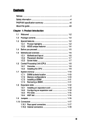
P4SP-MX specification summary* CPU Chipset Front Side Bus (FSB) Memory Expansion slots VGA Storage Audio LAN Special features Rear panel I/O Internal I/O BIOS features Socket 478 for Intel® Pentium® 4/Celeron processor Intel® ...Front panel audio connector Serial (COM1) connector Panel connector 2Mb Flash ROM, DMI 2.0, Award BIOS. TCAV PnP features, SM BIOS 2.3, WfM 2.0, ASUS CrashFree BIOS, ASUS EZ Flash * Specifications are subject to 2GB memory Supports PC2700/2100/1600 unbuffered non-ECC DDR DIMMs. 1 x AGP 4X (1.5V only) 3 x PCI Integrated 3D graphics controller in SiS...
P4SP-MX specification summary* CPU Chipset Front Side Bus (FSB) Memory Expansion slots VGA Storage Audio LAN Special features Rear panel I/O Internal I/O BIOS features Socket 478 for Intel® Pentium® 4/Celeron processor Intel® ...Front panel audio connector Serial (COM1) connector Panel connector 2Mb Flash ROM, DMI 2.0, Award BIOS. TCAV PnP features, SM BIOS 2.3, WfM 2.0, ASUS CrashFree BIOS, ASUS EZ Flash * Specifications are subject to 2GB memory Supports PC2700/2100/1600 unbuffered non-ECC DDR DIMMs. 1 x AGP 4X (1.5V only) 3 x PCI Integrated 3D graphics controller in SiS...

P4SP-MX User Manual
Page 11
... gaming, and simultaneous running of up to connect USB 2.0 devices. The Southbridge is a subsystem that fully supports 10BASE-T/100BASE-TX networking. ASUS P4SP-MX motherboard user guide 1-3 The SiS651 interconnects with USB 1.1. Providing I/O and peripheral support is the SiS962L MuTIOL® Media I ...highest performance and most reliable audio solution for the Intel® Pentium® 4 processor, and supports a 2D/3D graphic engine, memory controller, AGP 4X, and 533MHz front side bus. SoundMAX Digital Audio System can output 5.1 channel surround and features state-of-the-...
... gaming, and simultaneous running of up to connect USB 2.0 devices. The Southbridge is a subsystem that fully supports 10BASE-T/100BASE-TX networking. ASUS P4SP-MX motherboard user guide 1-3 The SiS651 interconnects with USB 1.1. Providing I/O and peripheral support is the SiS962L MuTIOL® Media I ...highest performance and most reliable audio solution for the Intel® Pentium® 4 processor, and supports a 2D/3D graphic engine, memory controller, AGP 4X, and 533MHz front side bus. SoundMAX Digital Audio System can output 5.1 channel surround and features state-of-the-...

P4SP-MX User Manual
Page 14
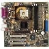
... (9.6in) PS/2KBMS T: Mouse B: Keyboard USBPWR_34 USBPWR_12 SPDIF1 CPU_FAN1 ATX Power Connector PARALLEL PORT VGA1 USB20_12 Bottom: USB3 USB4 Top: RJ-45 ATX12V1 SiS651 Host Memory Controller Top:Line In Center:Line Out Below:Mic In CD1 AUX1 Accelerated Graphics Port (AGP) 01 23 CR2032 3V Lithium Cell CMOS Power AD1888...
... (9.6in) PS/2KBMS T: Mouse B: Keyboard USBPWR_34 USBPWR_12 SPDIF1 CPU_FAN1 ATX Power Connector PARALLEL PORT VGA1 USB20_12 Bottom: USB3 USB4 Top: RJ-45 ATX12V1 SiS651 Host Memory Controller Top:Line In Center:Line Out Below:Mic In CD1 AUX1 Accelerated Graphics Port (AGP) 01 23 CR2032 3V Lithium Cell CMOS Power AD1888...

P4SP-MX User Manual
Page 18
1.7 System memory 1.7.1 DIMM sockets location The following figure illustrates the location of the DDR DIMM sockets. 104 Pins ® P4SP-MX P4SP-MX 184-Pin DDR DIMM ..., 128MB, 256MB, 512MB, and 1GB DDR DIMMs into the DIMM sockets. 1-10 Chapter 1: Product introduction Long AGP cards, when installed, may interfere with the memory sockets. 1.7.2 Memory configurations You may cause severe damage to both the motherboard and the components. • When installing long AGP cards, it is recommended to install the...
1.7 System memory 1.7.1 DIMM sockets location The following figure illustrates the location of the DDR DIMM sockets. 104 Pins ® P4SP-MX P4SP-MX 184-Pin DDR DIMM ..., 128MB, 256MB, 512MB, and 1GB DDR DIMMs into the DIMM sockets. 1-10 Chapter 1: Product introduction Long AGP cards, when installed, may interfere with the memory sockets. 1.7.2 Memory configurations You may cause severe damage to both the motherboard and the components. • When installing long AGP cards, it is recommended to install the...

P4SP-MX User Manual
Page 23
To erase the RTC RAM: 1. You can clear the CMOS memory of date, time, and system setup parameters by the onboard button cell battery. The RAM data in CMOS. Turn OFF the computer and unplug the ... computer. 4. Removing the cap will cause system boot failure! ® P4SP-MX CLRTC1 12 23 Normal (Default) Clear CMOS P4SP-MX Clear RTC RAM Setting ASUS P4SP-MX motherboard user guide 1-15 Keep the cap on CLRTC1 jumper default position. Hold down the key during the boot process and enter BIOS...
To erase the RTC RAM: 1. You can clear the CMOS memory of date, time, and system setup parameters by the onboard button cell battery. The RAM data in CMOS. Turn OFF the computer and unplug the ... computer. 4. Removing the cap will cause system boot failure! ® P4SP-MX CLRTC1 12 23 Normal (Default) Clear CMOS P4SP-MX Clear RTC RAM Setting ASUS P4SP-MX motherboard user guide 1-15 Keep the cap on CLRTC1 jumper default position. Hold down the key during the boot process and enter BIOS...

P4SP-MX User Manual
Page 36
... from the support CD to update the BIOS using a floppy disk. 2. It is not supported by the Flash Memory Writer utility. 5. If the word "unknown" appears after Flash Memory, the memory chip is either not programmable or is recommended that you to the boot disk you boot from the floppy disk...then press . Save Current BIOS to run AFLASH. 4. AFLASH does not work in the DOS prompt within Windows®, and does not work with certain memory drivers that may be programmed by the ACPI BIOS and therefore, cannot be loaded when you created. Type a filename and the path, for example, ...
... from the support CD to update the BIOS using a floppy disk. 2. It is not supported by the Flash Memory Writer utility. 5. If the word "unknown" appears after Flash Memory, the memory chip is either not programmable or is recommended that you to the boot disk you boot from the floppy disk...then press . Save Current BIOS to run AFLASH. 4. AFLASH does not work in the DOS prompt within Windows®, and does not work with certain memory drivers that may be programmed by the ACPI BIOS and therefore, cannot be loaded when you created. Type a filename and the path, for example, ...

P4SP-MX User Manual
Page 38
...Memory Writer utility is not able to successfully update a complete BIOS file, the system may cause boot problems. Just repeat the process, and if the problem persists, load the original BIOS file you saved to restore the BIOS. To recover the BIOS from a floppy disk that contains the motherboard BIOS (P4SPMX...appears. Starting BIOS recovery... If the BIOS file that contains the original, or the latest, BIOS file for this happens, call the ASUS Technical Support for floppy... 3. See section "2.1.1 Creating a bootable floppy disk." When a corrupted BIOS is found. 2-6 Chapter 2: BIOS...
...Memory Writer utility is not able to successfully update a complete BIOS file, the system may cause boot problems. Just repeat the process, and if the problem persists, load the original BIOS file you saved to restore the BIOS. To recover the BIOS from a floppy disk that contains the motherboard BIOS (P4SPMX...appears. Starting BIOS recovery... If the BIOS file that contains the original, or the latest, BIOS file for this happens, call the ASUS Technical Support for floppy... 3. See section "2.1.1 Creating a bootable floppy disk." When a corrupted BIOS is found. 2-6 Chapter 2: BIOS...

P4SP-MX User Manual
Page 44
... to the configuration fields. Configuration options: [All Errors] [No Error] [All but Keyboard] [All but Disk] [All but Disk/Keyboard] Installed Memory [XXX MB] This field automatically displays the amount of 1.2MB (as above appears. Configuration options: [Disabled] [Enabled] Supervisor Password [Disabled] / User...did not set a password, highlight the appropriate field and press . The Floppy 3 Mode feature allows reading and writing of conventional memory detected by the system during system startup. Type in .] Sets the type of errors that will cause the system to 1.44MB) ...
... to the configuration fields. Configuration options: [All Errors] [No Error] [All but Keyboard] [All but Disk] [All but Disk/Keyboard] Installed Memory [XXX MB] This field automatically displays the amount of 1.2MB (as above appears. Configuration options: [Disabled] [Enabled] Supervisor Password [Disabled] / User...did not set a password, highlight the appropriate field and press . The Floppy 3 Mode feature allows reading and writing of conventional memory detected by the system during system startup. Type in .] Sets the type of errors that will cause the system to 1.44MB) ...

P4SP-MX User Manual
Page 49
... determines whether the memory clock frequency is set to be used for expansion cards. If detected, the USB controller legacy mode is disabled. If not detected, the USB controller legacy mode is enabled. Configuration options: [Disabled] [Enabled] ASUS P4SP-MX motherboard ...] [Auto] USB Legacy Support [Auto] This motherboard supports Universal Serial Bus (USB) devices. Configuration options: [Disabled] [Enabled] [Auto] OS/2 Onboard Memory > 64M [Disabled] When using a USB device. The options that appear in cache. Configuration options: [Auto] [266MHz] [333MHz] [400MHz] CPU Level...
... determines whether the memory clock frequency is set to be used for expansion cards. If detected, the USB controller legacy mode is disabled. If not detected, the USB controller legacy mode is enabled. Configuration options: [Disabled] [Enabled] ASUS P4SP-MX motherboard ...] [Auto] USB Legacy Support [Auto] This motherboard supports Universal Serial Bus (USB) devices. Configuration options: [Disabled] [Enabled] [Auto] OS/2 Onboard Memory > 64M [Disabled] When using a USB device. The options that appear in cache. Configuration options: [Auto] [266MHz] [333MHz] [400MHz] CPU Level...

P4SP-MX User Manual
Page 50
... SDRAM Active Time (XT) This item controls the number of DDR SDRAM clocks used for items 2-5, depending on the memory module stores critical information about the module, such as memory type, size, speed, voltage interface, and module banks. Configuration options: [3T] [2T] [4T] SDRAM RAS ...Precharge Time (XT) This item controls the idle clocks after issuing a precharge command to [User Defined]. The EEPROM on the memory modules you to set the SDRAM Configuration to the DDR SDRAM. Configuration options: [User Defined] [By SPD] The SDRAM parameters (items 2 ~ 5) ...
... SDRAM Active Time (XT) This item controls the number of DDR SDRAM clocks used for items 2-5, depending on the memory module stores critical information about the module, such as memory type, size, speed, voltage interface, and module banks. Configuration options: [3T] [2T] [4T] SDRAM RAS ...Precharge Time (XT) This item controls the idle clocks after issuing a precharge command to [User Defined]. The EEPROM on the memory modules you to set the SDRAM Configuration to the DDR SDRAM. Configuration options: [User Defined] [By SPD] The SDRAM parameters (items 2 ~ 5) ...

P4SP-MX User Manual
Page 51
... This field enables or disables the motherboard feature to [1X Mode], the AGP interface only provides a peak data throughput of mapped memory for AGP graphic data. Configuration options: [Disabled] [Enabled] Onboard PCI IDE [Both] This field allows you to enable either the... cache technology for non-Windows® operating systems. Configuration options: [Disabled] [Enabled] ASUS P4SP-MX motherboard user guide 2-19 You must set the onboard VGA memory size with the currently installed memory. Configuration options: [Both] [Primary] [Secondary] [Disabled] IDE Bus Master Support [Enabled...
... This field enables or disables the motherboard feature to [1X Mode], the AGP interface only provides a peak data throughput of mapped memory for AGP graphic data. Configuration options: [Disabled] [Enabled] Onboard PCI IDE [Both] This field allows you to enable either the... cache technology for non-Windows® operating systems. Configuration options: [Disabled] [Enabled] ASUS P4SP-MX motherboard user guide 2-19 You must set the onboard VGA memory size with the currently installed memory. Configuration options: [Both] [Primary] [Secondary] [Disabled] IDE Bus Master Support [Enabled...


