
Motherboard DIY Troubleshooting Guide
Page 12
... 2-15 and 2-16. 1-2 Chapter 1: Product introduction This motherboard supports 800/533/400 MHz system front side bus that allows 6.4GB/s, 4.3GB/s and 3.2GB/s data transfer rates, respectively. 1.1 Welcome! The ASUS P4R800-VM motherboard delivers a host of new features and latest technologies making it... in your package with the list below. 1.2 Package contents Check your P4R800-VM package for the following items. ASUS P4R800-VM motherboard Micro-ATX form factor: 9.6 in x 9.6 in (24.5 cm x 24.5 cm) ASUS P4R800-VM series support CD Serial (COM) port module and cable 80-conductor Ultra...
... 2-15 and 2-16. 1-2 Chapter 1: Product introduction This motherboard supports 800/533/400 MHz system front side bus that allows 6.4GB/s, 4.3GB/s and 3.2GB/s data transfer rates, respectively. 1.1 Welcome! The ASUS P4R800-VM motherboard delivers a host of new features and latest technologies making it... in your package with the list below. 1.2 Package contents Check your P4R800-VM package for the following items. ASUS P4R800-VM motherboard Micro-ATX form factor: 9.6 in x 9.6 in (24.5 cm x 24.5 cm) ASUS P4R800-VM series support CD Serial (COM) port module and cable 80-conductor Ultra...
Motherboard DIY Troubleshooting Guide
Page 13
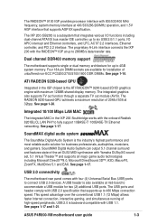
.... SoundMAX Digital Audio System can output 5.1 channel surround and features state-of 2048x1536 at mid-board to 480 Mbps connection speed. ASUS P4R800-VM motherboard user guide 1-3 The integrated graphics also supports TV out function through a separate TV out module (AV/S). USB 2.0 is the ... that supports up to accommodate a USB module for up to 266MB/s data transfer rate. Dual channel DDR400 memory support The motherboard supports single or dual memory architecture for two (2) additional USB ports. SoundMAX digital audio system The SoundMax Digital Audio System is...
.... SoundMAX Digital Audio System can output 5.1 channel surround and features state-of 2048x1536 at mid-board to 480 Mbps connection speed. ASUS P4R800-VM motherboard user guide 1-3 The integrated graphics also supports TV out function through a separate TV out module (AV/S). USB 2.0 is the ... that supports up to accommodate a USB module for up to 266MB/s data transfer rate. Dual channel DDR400 memory support The motherboard supports single or dual memory architecture for two (2) additional USB ports. SoundMAX digital audio system The SoundMax Digital Audio System is...

Motherboard DIY Troubleshooting Guide
Page 15
P4R800-VM P4R800-VM Onboard LED SB_PWR1 ON Standby Power OFF Powered Off ASUS P4R800-VM motherboard user guide 1-5 Use a grounded wrist strap or touch a safely grounded object or to avoid damaging them . 4. The green LED lights up to indicates that the ... you uninstall any component, place it on them due to shut down the system and unplug the power cable before removing or plugging in any motherboard component. Whenever you to static electricity. 3. Unplug the power cord from the power supply. Before you install...
P4R800-VM P4R800-VM Onboard LED SB_PWR1 ON Standby Power OFF Powered Off ASUS P4R800-VM motherboard user guide 1-5 Use a grounded wrist strap or touch a safely grounded object or to avoid damaging them . 4. The green LED lights up to indicates that the ... you uninstall any component, place it on them due to shut down the system and unplug the power cable before removing or plugging in any motherboard component. Whenever you to static electricity. 3. Unplug the power cord from the power supply. Before you install...

Motherboard DIY Troubleshooting Guide
Page 17
Place this side towards the rear of the chassis as indicated in the image below. 1.5.3 Screw holes Place eight (8) screws into the chassis in the correct orientation. 1.5.2 Placement direction When installing the motherboard, make sure that you place it into the holes indicated by circles to secure the motherboard to the chassis. Doing so may damage the motherboard. Do not overtighten the screws! The edge with external ports goes to the rear part of the chassis ASUS P4R800-VM motherboard user guide 1-7
Place this side towards the rear of the chassis as indicated in the image below. 1.5.3 Screw holes Place eight (8) screws into the chassis in the correct orientation. 1.5.2 Placement direction When installing the motherboard, make sure that you place it into the holes indicated by circles to secure the motherboard to the chassis. Doing so may damage the motherboard. Do not overtighten the screws! The edge with external ports goes to the rear part of the chassis ASUS P4R800-VM motherboard user guide 1-7

Motherboard DIY Troubleshooting Guide
Page 19
...CPU is locked. 6. Position the CPU above the socket such that it is in one correct orientation. Gold Mark ASUS P4R800-VM motherboard user guide 1-9 Locate the 478-pin ZIF socket on the motherboard. 2. Unlock the socket by pressing the lever sideways, then lift it fits in completely. 90 - 100 3.... 1.6.2 Installing the CPU Follow these steps to the CPU_FAN1 connector on the motherboard. DO NOT force the CPU into the socket...
...CPU is locked. 6. Position the CPU above the socket such that it is in one correct orientation. Gold Mark ASUS P4R800-VM motherboard user guide 1-9 Locate the 478-pin ZIF socket on the motherboard. 2. Unlock the socket by pressing the lever sideways, then lift it fits in completely. 90 - 100 3.... 1.6.2 Installing the CPU Follow these steps to the CPU_FAN1 connector on the motherboard. DO NOT force the CPU into the socket...

Motherboard DIY Troubleshooting Guide
Page 21
Populated - (4) - - - SS W942508BH-5 SS V58C2256804SAT5 Obtain DDR DIMMs only from ASUS qualified vendors. ASUS P4R800-VM motherboard user guide 1-11 Populated - Populated Dual-channel (PC2700/PC2100/ PC1600) (1) Populated - Double-sided SS - Populated - (2) - Size Vendor Part Number Chip Brand Sides Chip Number 256MB ...
Populated - (4) - - - SS W942508BH-5 SS V58C2256804SAT5 Obtain DDR DIMMs only from ASUS qualified vendors. ASUS P4R800-VM motherboard user guide 1-11 Populated - Populated Dual-channel (PC2700/PC2100/ PC1600) (1) Populated - Double-sided SS - Populated - (2) - Size Vendor Part Number Chip Brand Sides Chip Number 256MB ...

Motherboard DIY Troubleshooting Guide
Page 23
... 14* 9 Primary IDE Channel 15* 10 Secondary IDE Channel * These IRQs are usually available for ISA or PCI devices. 1.8.2 IRQ assignments for this motherboard PCI slot 1 PCI slot 2 PCI slot 3 AGP slot Onboard USB controller 1 Onboard USB controller 2 Onboard USB controller 3 Onboard USB 2.0 controller Onboard... PCI cards on shared slots, ensure that the drivers support "Share IRQ" or that the cards do not need IRQ assignments. ASUS P4R800-VM motherboard user guide 1-13 used - - shared - - - shared - - - shared - - shared - - shared shared - - -
... 14* 9 Primary IDE Channel 15* 10 Secondary IDE Channel * These IRQs are usually available for ISA or PCI devices. 1.8.2 IRQ assignments for this motherboard PCI slot 1 PCI slot 2 PCI slot 3 AGP slot Onboard USB controller 1 Onboard USB controller 2 Onboard USB controller 3 Onboard USB 2.0 controller Onboard... PCI cards on shared slots, ensure that the drivers support "Share IRQ" or that the cards do not need IRQ assignments. ASUS P4R800-VM motherboard user guide 1-13 used - - shared - - - shared - - - shared - - shared - - shared shared - - -
Motherboard DIY Troubleshooting Guide
Page 25
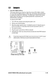
... clearing the RTC RAM, never remove the cap on pins 2-3 for about 5~10 seconds, then move the cap back to pins 2-3. P4R800-VM P4R800-VM Clear RTC RAM CLRTC1 2 1 Normal (Default) 3 2 Clear CMOS ASUS P4R800-VM motherboard user guide 1-15 1.9 Jumpers 1. Hold down the key during the boot process and enter BIOS setup to clear the Real Time...
... clearing the RTC RAM, never remove the cap on pins 2-3 for about 5~10 seconds, then move the cap back to pins 2-3. P4R800-VM P4R800-VM Clear RTC RAM CLRTC1 2 1 Normal (Default) 3 2 Clear CMOS ASUS P4R800-VM motherboard user guide 1-15 1.9 Jumpers 1. Hold down the key during the boot process and enter BIOS setup to clear the Real Time...
Motherboard DIY Troubleshooting Guide
Page 27
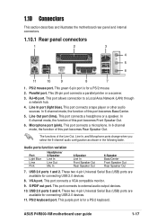
... connects to a Local Area Network (LAN) through a network hub. 4. PS/2 mouse port. USB 2.0 ports 3 and 4. Line In port (light blue). ASUS P4R800-VM motherboard user guide 1-17 1.10 Connectors This section describes and illustrates the motherboard rear panel and internal connectors. 1.10.1 Rear panel connectors 1 2 3 4 5 6 11 10 9 8 7 1. This purple port is for connecting USB 2.0 devices...
... connects to a Local Area Network (LAN) through a network hub. 4. PS/2 mouse port. USB 2.0 ports 3 and 4. Line In port (light blue). ASUS P4R800-VM motherboard user guide 1-17 1.10 Connectors This section describes and illustrates the motherboard rear panel and internal connectors. 1.10.1 Rear panel connectors 1 2 3 4 5 6 11 10 9 8 7 1. This purple port is for connecting USB 2.0 devices...

Motherboard DIY Troubleshooting Guide
Page 29
...8A on the +12V lead and at least 1A on the +5-volt standby lead (+5VSB). P4R800-VM CD(Black) AUX(White) Right Audio Channel Ground Ground Left Audio Channel P4R800-VM Internal Audio Connectors ASUS P4R800-VM motherboard user guide 1-19 The plugs from sound sources such as a optical drive, TV tuner,... connect the 4-pin ATX +12V power plug to provide sufficient power to fit these connectors in only one orientation. 3. P4R800-VM ATX12V1 +12V DC GND +12V DC GND P4R800-VM ATX Power Connector ATXPWR1 +12.0VDC +5VSB PWR_OK COM +5.0VDC COM +5.0VDC COM +3.3VDC +3.3VDC +5.0VDC +5.0VDC ...
...8A on the +12V lead and at least 1A on the +5-volt standby lead (+5VSB). P4R800-VM CD(Black) AUX(White) Right Audio Channel Ground Ground Left Audio Channel P4R800-VM Internal Audio Connectors ASUS P4R800-VM motherboard user guide 1-19 The plugs from sound sources such as a optical drive, TV tuner,... connect the 4-pin ATX +12V power plug to provide sufficient power to fit these connectors in only one orientation. 3. P4R800-VM ATX12V1 +12V DC GND +12V DC GND P4R800-VM ATX Power Connector ATXPWR1 +12.0VDC +5VSB PWR_OK COM +5.0VDC COM +5.0VDC COM +3.3VDC +3.3VDC +5.0VDC +5.0VDC ...

Motherboard DIY Troubleshooting Guide
Page 31
...an optional USB 2.0 module to hear system beeps and warnings. USB+5V USB_P6USB_P6+ GND NC USB+5V USB_P5USB_P5+ GND P4R800-VM USB56 1 P4R800-VM USB 2.0 Header The USB module is available for connecting next generation USB peripherals such as high resolution cameras, scanners, and... If the USB ports on the rear panel are inadequate, a USB header is purchased separately. P4R800-VM SPEAK1 1 +5V GND GND Speak Out P4R800-VM Speaker Out Connector 8. ASUS P4R800-VM motherboard user guide 1-21 Speaker out connector (4-pin SPEAK1) This connector connects to the case-mounted speaker...
...an optional USB 2.0 module to hear system beeps and warnings. USB+5V USB_P6USB_P6+ GND NC USB+5V USB_P5USB_P5+ GND P4R800-VM USB56 1 P4R800-VM USB 2.0 Header The USB module is available for connecting next generation USB peripherals such as high resolution cameras, scanners, and... If the USB ports on the rear panel are inadequate, a USB header is purchased separately. P4R800-VM SPEAK1 1 +5V GND GND Speak Out P4R800-VM Speaker Out Connector 8. ASUS P4R800-VM motherboard user guide 1-21 Speaker out connector (4-pin SPEAK1) This connector connects to the case-mounted speaker...

Motherboard DIY Troubleshooting Guide
Page 33
The power LED lead (PLED1) is for the system power LED. P4R800-VM Power LED+ Power LEDPower Switch Ground Power LED Power Switch F_PANEL1 IDE LED+ IDE LED- If your motherboard package comes with a 2-pin to 3-pin power LED converter, connect the 2-pin plug to this ...LED lights up when you turn on the system power, and blinks when the system is in sleep mode. P4R800-VM P4R800-VM PLED Setting PLED1 1 PLED+ NC PLED- 12. ASUS P4R800-VM motherboard user guide 1-23 System panel connector (10-1 pin F_PANEL1) This connector accommodates several chassis-mounted functions. The...
The power LED lead (PLED1) is for the system power LED. P4R800-VM Power LED+ Power LEDPower Switch Ground Power LED Power Switch F_PANEL1 IDE LED+ IDE LED- If your motherboard package comes with a 2-pin to 3-pin power LED converter, connect the 2-pin plug to this ...LED lights up when you turn on the system power, and blinks when the system is in sleep mode. P4R800-VM P4R800-VM PLED Setting PLED1 1 PLED+ NC PLED- 12. ASUS P4R800-VM motherboard user guide 1-23 System panel connector (10-1 pin F_PANEL1) This connector accommodates several chassis-mounted functions. The...

Motherboard DIY Troubleshooting Guide
Page 37
... on the screen is for the extension name. What you to copy the original BIOS file to a floppy diskette. All rights reserved. All rights reserved. ASUS P4R800-VM motherboard user guide 2-3 2.1.2 Using AFUDOS to copy the current BIOS The AFUDOS is a DOS-based application that the floppy disk is not write-protected and have...
... on the screen is for the extension name. What you to copy the original BIOS file to a floppy diskette. All rights reserved. All rights reserved. ASUS P4R800-VM motherboard user guide 2-3 2.1.2 Using AFUDOS to copy the current BIOS The AFUDOS is a DOS-based application that the floppy disk is not write-protected and have...
Motherboard DIY Troubleshooting Guide
Page 39
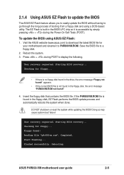
...the long process of booting from a floppy disk and using ASUS EZ Flash: 1. Save the BIOS file to P4R800VM.ROM. Checking for floppy... • If there is built-in the floppy disk, the error message "P4R800VM.ROM not found!" 4. DO NOT shutdown or reset the ... system when done. Visit the ASUS website (www.asus.com) to display the following. If the P4R800VM.ROM file is accessible by simply pressing + during POST to download the latest BIOS file for floppy... Completed. Starting BIOS recovery... Reboot the system. 3. ASUS P4R800-VM motherboard user guide 2-5 Press + during...
...the long process of booting from a floppy disk and using ASUS EZ Flash: 1. Save the BIOS file to P4R800VM.ROM. Checking for floppy... • If there is built-in the floppy disk, the error message "P4R800VM.ROM not found!" 4. DO NOT shutdown or reset the ... system when done. Visit the ASUS website (www.asus.com) to display the following. If the P4R800VM.ROM file is accessible by simply pressing + during POST to download the latest BIOS file for floppy... Completed. Starting BIOS recovery... Reboot the system. 3. ASUS P4R800-VM motherboard user guide 2-5 Press + during...
Motherboard DIY Troubleshooting Guide
Page 41
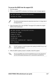
... reset the system while updating the BIOS! ASUS P4R800-VM motherboard user guide 2-7 Bad BIOS checksum. Checking for CD-ROM... Checking for floppy... Reading file "p4r800vm.rom". Completed. Doing so may not be the latest BIOS version for this motherboard. The recovered BIOS may cause system boot ...failure! 4. Visit the ASUS website (www.asus.com) to download the latest BIOS file. Place ...
... reset the system while updating the BIOS! ASUS P4R800-VM motherboard user guide 2-7 Bad BIOS checksum. Checking for CD-ROM... Checking for floppy... Reading file "p4r800vm.rom". Completed. Doing so may not be the latest BIOS version for this motherboard. The recovered BIOS may cause system boot ...failure! 4. Visit the ASUS website (www.asus.com) to download the latest BIOS file. Place ...

Motherboard DIY Troubleshooting Guide
Page 43
Use the navigation keys to select items in .] [ST321122A] [ASUS CDS520/] [Not Detected] [Not Detected] Use [ENTER], [TAB] or [SHIFT-TAB] to select a field. Some of a menu screen are the navigation keys for that particular ... IDE Slave Secondary IDE Master Secondary IDE Slave System Information [11:10:19] [Thu, 09/27/2003] [1.44M, 3.5 in the menu and change the settings. ASUS P4R800-VM motherboard user guide 2-9 Sub-menu items Navigation keys 2.2.2 Menu bar The menu bar on top of the screen has the following main items: Main Advanced Power...
Use the navigation keys to select items in .] [ST321122A] [ASUS CDS520/] [Not Detected] [Not Detected] Use [ENTER], [TAB] or [SHIFT-TAB] to select a field. Some of a menu screen are the navigation keys for that particular ... IDE Slave Secondary IDE Master Secondary IDE Slave System Information [11:10:19] [Thu, 09/27/2003] [1.44M, 3.5 in the menu and change the settings. ASUS P4R800-VM motherboard user guide 2-9 Sub-menu items Navigation keys 2.2.2 Menu bar The menu bar on top of the screen has the following main items: Main Advanced Power...

Motherboard DIY Troubleshooting Guide
Page 45
...IDE Master Primary IDE Slave Secondary IDE Master Secondary IDE Slave System Information [11:10:19] [Thu, 09/27/2003] [1.44M, 3.5 in .] ASUS P4R800-VM motherboard user guide 2-11 Configuration options: [Disabled] [360K, 5.25 in.] [1.2M , 5.25 in.] [720K , 3.5 in.] [1.44M, 3.5 in.] [2.88M, 3.5 in .] [ST321122A...] [ASUS CDS520/] [Not Detected] [Not Detected] Use [ENTER], [TAB] or [SHIFT-TAB] to navigate through them. 2.3 Main menu When you enter the BIOS Setup program,...
...IDE Master Primary IDE Slave Secondary IDE Master Secondary IDE Slave System Information [11:10:19] [Thu, 09/27/2003] [1.44M, 3.5 in .] ASUS P4R800-VM motherboard user guide 2-11 Configuration options: [Disabled] [360K, 5.25 in.] [1.2M , 5.25 in.] [720K , 3.5 in.] [1.44M, 3.5 in.] [2.88M, 3.5 in .] [ST321122A...] [ASUS CDS520/] [Not Detected] [Not Detected] Use [ENTER], [TAB] or [SHIFT-TAB] to navigate through them. 2.3 Main menu When you enter the BIOS Setup program,...

Motherboard DIY Troubleshooting Guide
Page 47
.../03 Processor Type : Intel(R) Pentium(R) 4 CPU 1.73GHz Speed : 1733 MHz Count : 1 System Memory Size : 256MB AMI BIOS This item displays the auto-detected BIOS information. ASUS P4R800-VM motherboard user guide 2-13 System Memory This item displays the auto-detected system memory. Configuration options: [Disabled] [Enabled] 2.3.5 System Information This menu gives you an overview...
.../03 Processor Type : Intel(R) Pentium(R) 4 CPU 1.73GHz Speed : 1733 MHz Count : 1 System Memory Size : 256MB AMI BIOS This item displays the auto-detected BIOS information. ASUS P4R800-VM motherboard user guide 2-13 System Memory This item displays the auto-detected system memory. Configuration options: [Disabled] [Enabled] 2.3.5 System Information This menu gives you an overview...
Motherboard DIY Troubleshooting Guide
Page 49
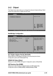
Select an item then press Enter to use as primary boot device. Configuration options: [32MB] [64MB] [128MB] [256MB] [512MB] ASUS P4R800-VM motherboard user guide 2-15 2.4.2 Chipset The Chipset menu items allow you to select DRAM CAS speed. Graphic Adapter Priority DRAM CAS Select AGP Aperture Size UMA ...
Select an item then press Enter to use as primary boot device. Configuration options: [32MB] [64MB] [128MB] [256MB] [512MB] ASUS P4R800-VM motherboard user guide 2-15 2.4.2 Chipset The Chipset menu items allow you to select DRAM CAS speed. Graphic Adapter Priority DRAM CAS Select AGP Aperture Size UMA ...

Motherboard DIY Troubleshooting Guide
Page 51
... Parallel Port version. Configuration options: [Normal] [Bi-Directional] [EPP] [ECP] EPP Version [1.9] Allows you to select the Parallel Port base address. Configuration options: [IRQ5] [IRQ7] ASUS P4R800-VM motherboard user guide 2-17 Serial Port Address [3F8/IRQ4] Allows you to select the Parallel Port mode. Configuration options: [Disabled] [3F8/IRQ4] [3E8/IRQ4] [2E8/IRQ3...
... Parallel Port version. Configuration options: [Normal] [Bi-Directional] [EPP] [ECP] EPP Version [1.9] Allows you to select the Parallel Port base address. Configuration options: [IRQ5] [IRQ7] ASUS P4R800-VM motherboard user guide 2-17 Serial Port Address [3F8/IRQ4] Allows you to select the Parallel Port mode. Configuration options: [Disabled] [3F8/IRQ4] [3E8/IRQ4] [2E8/IRQ3...


