Motherboard DIY Troubleshooting Guide
Page 9
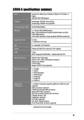
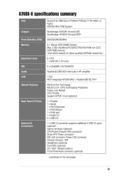
...; nForce2 MCP 400/333/266/200Mhz 3 x 184-pin DDR DIMM Sockets Max. 3 GB unbuffered PC3200/2700/2100/1600 non-ECC DDR RAM memory. (Visit ASUS website for latest qualified DDR400 module list.) 5 x PCI 1 x AGP 8X (1.5V only) 2 x UltraDMA 133/100/66/33 Realtek... ALC650 6CH with built-in HP amplifier 1 Port MCP integrated NVIDIA MAC + Realtek 8201BL PHY ASUS Q-Fan Technology ASUS C.O.P. (CPU Overheating Protection) Power Loss Restart CPU Throttle Support S/PDIF in/out (optional) 1 x Parallel 1 x Serial 1 x PS/2 Keyboard 1 x PS/2 Mouse 1 x RJ45 port 1 ...
...; nForce2 MCP 400/333/266/200Mhz 3 x 184-pin DDR DIMM Sockets Max. 3 GB unbuffered PC3200/2700/2100/1600 non-ECC DDR RAM memory. (Visit ASUS website for latest qualified DDR400 module list.) 5 x PCI 1 x AGP 8X (1.5V only) 2 x UltraDMA 133/100/66/33 Realtek... ALC650 6CH with built-in HP amplifier 1 Port MCP integrated NVIDIA MAC + Realtek 8201BL PHY ASUS Q-Fan Technology ASUS C.O.P. (CPU Overheating Protection) Power Loss Restart CPU Throttle Support S/PDIF in/out (optional) 1 x Parallel 1 x Serial 1 x PS/2 Keyboard 1 x PS/2 Mouse 1 x RJ45 port 1 ...

Motherboard DIY Troubleshooting Guide
Page 21
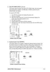
...optional) This jumper clears the Real Time Clock (RTC) RAM of date, time and system setup parameters in the BIOS (see section 2.5.1 Power Up Control). ® A7N8X-X KBPWR1 12 +5V (Default) 23 +5VSB A7N8X-X Keyboard Power Setting ASUS A7N8X-X Motherboard 1-11 This feature requires an ATX power ...supply that can supply at least 1A on the keyboard (the default value is powered by the onboard button cell battery. The RAM data in CMOS is [Disabled]). Turn OFF ...
...optional) This jumper clears the Real Time Clock (RTC) RAM of date, time and system setup parameters in the BIOS (see section 2.5.1 Power Up Control). ® A7N8X-X KBPWR1 12 +5V (Default) 23 +5VSB A7N8X-X Keyboard Power Setting ASUS A7N8X-X Motherboard 1-11 This feature requires an ATX power ...supply that can supply at least 1A on the keyboard (the default value is powered by the onboard button cell battery. The RAM data in CMOS is [Disabled]). Turn OFF ...

Motherboard DIY Troubleshooting Guide
Page 36
... the Setup program, you with its test routines. Use the BIOS Setup program when you can recognize these changes and record them in the CMOS RAM of your system, or prompted to use as possible. Even if you are not prompted to "Run Setup". It is constantly being updated, the following...
... the Setup program, you with its test routines. Use the BIOS Setup program when you can recognize these changes and record them in the CMOS RAM of your system, or prompted to use as possible. Even if you are not prompted to "Run Setup". It is constantly being updated, the following...

Motherboard DIY Troubleshooting Guide
Page 48
...] [AGP VGA Card] 2-18 Chapter 2: BIOS Setup Disabled by default. Note that increasing voltage to the DDR can cause premature failure of system components. Video RAM Cacheable [Disabled] This field establishes whether or not the video...
...] [AGP VGA Card] 2-18 Chapter 2: BIOS Setup Disabled by default. Note that increasing voltage to the DDR can cause premature failure of system components. Video RAM Cacheable [Disabled] This field establishes whether or not the video...

Motherboard DIY Troubleshooting Guide
Page 50
... of the game port t0 201 by default. Disabling the game port makes the port unavailable. Configuration options: [5] [10] 2.4.4 Power Management Setup ACPI Suspend to RAM [Disabled] This field enables or disables suspension to access the next field, "ECP Mode Use DMA". EPP enables bidirectional parallel port operation; ECP+EPP enables...
... of the game port t0 201 by default. Disabling the game port makes the port unavailable. Configuration options: [5] [10] 2.4.4 Power Management Setup ACPI Suspend to RAM [Disabled] This field enables or disables suspension to access the next field, "ECP Mode Use DMA". EPP enables bidirectional parallel port operation; ECP+EPP enables...

Motherboard DIY Troubleshooting Guide
Page 54
The password is set to [Disabled]. This password permits full access to erase the RTC RAM. 2.6 Hardware Monitor Menu The Harware Monitor menu displays all vital system statistics. 2-24 Chapter 2: BIOS Setup If you forget a password, you can type up to [... this field and press . The password is now set a password, highlight the appropriate field and press . The RAM data containing the password information is powered by erasing the CMOS Real Time Clock (RTC) RAM. symbols and other characters are not useable. The default enables the setup option for more information about how...
The password is set to [Disabled]. This password permits full access to erase the RTC RAM. 2.6 Hardware Monitor Menu The Harware Monitor menu displays all vital system statistics. 2-24 Chapter 2: BIOS Setup If you forget a password, you can type up to [... this field and press . The password is now set a password, highlight the appropriate field and press . The RAM data containing the password information is powered by erasing the CMOS Real Time Clock (RTC) RAM. symbols and other characters are not useable. The default enables the setup option for more information about how...

Motherboard DIY Troubleshooting Guide
Page 56
Select [Yes] to the CMOS RAM. Discard Changes This option allows you to other menus and make other than system date, system time...saving the values to save your selections without saving changes, the program prompts with a message asking if you want to the non-volatile RAM. 2-26 Chapter 2: BIOS Setup Select Exit Saving Changes or make further changes. If you to the Setup program. Exit & Discard ... the changes that you select this option only if you do not want to the non-volatile RAM. The CMOS RAM is turned off. Pressing saves the changes while exiting.
Select [Yes] to the CMOS RAM. Discard Changes This option allows you to other menus and make other than system date, system time...saving the values to save your selections without saving changes, the program prompts with a message asking if you want to the non-volatile RAM. 2-26 Chapter 2: BIOS Setup Select Exit Saving Changes or make further changes. If you to the Setup program. Exit & Discard ... the changes that you select this option only if you do not want to the non-volatile RAM. The CMOS RAM is turned off. Pressing saves the changes while exiting.
A7N8X-X User's Manual
Page 9
...; nForce2 MCP 400/333/266/200Mhz 3 x 184-pin DDR DIMM Sockets Max. 3 GB unbuffered PC3200/2700/2100/1600 non-ECC DDR RAM memory. (Visit ASUS website for latest qualified DDR400 module list.) 5 x PCI 1 x AGP 8X (1.5V only) 2 x UltraDMA 133/100/66/33 Realtek... ALC650 6CH with built-in HP amplifier 1 Port MCP integrated NVIDIA MAC + Realtek 8201BL PHY ASUS Q-Fan Technology ASUS C.O.P. (CPU Overheating Protection) Power Loss Restart CPU Throttle Support S/PDIF in/out (optional) 1 x Parallel 1 x Serial 1 x PS/2 Keyboard 1 x PS/2 Mouse 1 x RJ45 port 1 ...
...; nForce2 MCP 400/333/266/200Mhz 3 x 184-pin DDR DIMM Sockets Max. 3 GB unbuffered PC3200/2700/2100/1600 non-ECC DDR RAM memory. (Visit ASUS website for latest qualified DDR400 module list.) 5 x PCI 1 x AGP 8X (1.5V only) 2 x UltraDMA 133/100/66/33 Realtek... ALC650 6CH with built-in HP amplifier 1 Port MCP integrated NVIDIA MAC + Realtek 8201BL PHY ASUS Q-Fan Technology ASUS C.O.P. (CPU Overheating Protection) Power Loss Restart CPU Throttle Support S/PDIF in/out (optional) 1 x Parallel 1 x Serial 1 x PS/2 Keyboard 1 x PS/2 Mouse 1 x RJ45 port 1 ...
A7N8X-X User's Manual
Page 21
... the power cord. 2. CLRTC1 1 2 ® 2 3 Clear CMOS A7N8X-X Normal (Default) A7N8X-X Clear RTC RAM 4. 3. Clear RTC RAM (CLRTC1) (optional) This jumper clears the Real Time Clock (RTC) RAM of date, time and system setup parameters in CMOS is [Disabled]). KBPWR1 1 2 +5V (Default) ® 2... 3 +5VSB A7N8X-X A7N8X-X Keyboard Power Setting ASUS A7N8X-X Motherboard 1-11 The RAM data in CMOS. Move the jumper caps from [1-2] to the original position, [1-2]. 4. This feature requires an ATX power supply ...
... the power cord. 2. CLRTC1 1 2 ® 2 3 Clear CMOS A7N8X-X Normal (Default) A7N8X-X Clear RTC RAM 4. 3. Clear RTC RAM (CLRTC1) (optional) This jumper clears the Real Time Clock (RTC) RAM of date, time and system setup parameters in CMOS is [Disabled]). KBPWR1 1 2 +5V (Default) ® 2... 3 +5VSB A7N8X-X A7N8X-X Keyboard Power Setting ASUS A7N8X-X Motherboard 1-11 The RAM data in CMOS. Move the jumper caps from [1-2] to the original position, [1-2]. 4. This feature requires an ATX power supply ...

A7N8X-X User's Manual
Page 36
... to "Run Setup". 2.2 BIOS Setup program This motherboard supports a programmable FLASH ROM that the computer can recognize these changes and record them in the CMOS RAM of your computer in section "2.1 Managing and updating your BIOS." Use the BIOS Setup program when you see on . If you wish to enter Setup...
... to "Run Setup". 2.2 BIOS Setup program This motherboard supports a programmable FLASH ROM that the computer can recognize these changes and record them in the CMOS RAM of your computer in section "2.1 Managing and updating your BIOS." Use the BIOS Setup program when you see on . If you wish to enter Setup...

A7N8X-X User's Manual
Page 48
... failure of VGA signals. Configuration options: [PCI VGA Card] [AGP VGA Card] 2-18 Chapter 2: BIOS Setup Disabled by default. Video RAM Cacheable [Disabled] This field establishes whether or not the video RAM is cacheable. Configuration options: [Enabled] [Disabled] DDR Reference Voltage [ 2.6V] This field sets the voltage limits for the voltage supplied...
... failure of VGA signals. Configuration options: [PCI VGA Card] [AGP VGA Card] 2-18 Chapter 2: BIOS Setup Disabled by default. Video RAM Cacheable [Disabled] This field establishes whether or not the video RAM is cacheable. Configuration options: [Enabled] [Disabled] DDR Reference Voltage [ 2.6V] This field sets the voltage limits for the voltage supplied...

A7N8X-X User's Manual
Page 50
... direction only; Configuration options: [Disabled] [201] [209] Onboard MIDI I/O [330] This field sets the address of the MIDI I/O port to RAM. Configuration options: [5] [10] 2.4.4 Power Management Setup ACPI Suspend to RAM [Disabled] This field enables or disables suspension to 330 by default. This selection is 3. Configuration options: [1] [3] Onboard Game Port [201] This...
... direction only; Configuration options: [Disabled] [201] [209] Onboard MIDI I/O [330] This field sets the address of the MIDI I/O port to RAM. Configuration options: [5] [10] 2.4.4 Power Management Setup ACPI Suspend to RAM [Disabled] This field enables or disables suspension to 330 by default. This selection is 3. Configuration options: [1] [3] Onboard Game Port [201] This...

A7N8X-X User's Manual
Page 54
...2: BIOS Setup symbols and other characters are not useable. To clear the password, highlight this field and press . Forgot the password? The RAM data containing the password information is set to [Enabled]. Type in a password then press . You can clear it by the onboard button cell... battery. The password is powered by erasing the CMOS Real Time Clock (RTC) RAM. NOTE: See section "1.9 Jumpers" for security. This password permits full access to eight alphanumeric characters; The same dialog box as above appears....
...2: BIOS Setup symbols and other characters are not useable. To clear the password, highlight this field and press . Forgot the password? The RAM data containing the password information is set to [Enabled]. Type in a password then press . You can clear it by the onboard button cell... battery. The password is powered by erasing the CMOS Real Time Clock (RTC) RAM. NOTE: See section "1.9 Jumpers" for security. This password permits full access to eight alphanumeric characters; The same dialog box as above appears....

A7N8X-X User's Manual
Page 56
... Exit menu to ensure the selected values are saved to save changes and exit. When selecting this option, a confirmation appears. Select [Yes] to the CMOS RAM. The CMOS RAM is turned off. Select Exit Saving Changes or make further changes. Discard Changes This option allows you to the non-volatile...
... Exit menu to ensure the selected values are saved to save changes and exit. When selecting this option, a confirmation appears. Select [Yes] to the CMOS RAM. The CMOS RAM is turned off. Select Exit Saving Changes or make further changes. Discard Changes This option allows you to the non-volatile...


