Motherboard DIY Troubleshooting Guide
Page 9
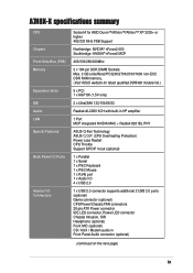
A7N8X-X specifications summary CPU Chipset Front Side Bus (FSB) Memory .../266/200Mhz 3 x 184-pin DDR DIMM Sockets Max. 3 GB unbuffered PC3200/2700/2100/1600 non-ECC DDR RAM memory. (Visit ASUS website for latest qualified DDR400 module list.) 5 x PCI 1 x AGP 8X (1.5V only) 2 x UltraDMA ...133/100/66/33 Realtek ALC650 6CH with built-in HP amplifier 1 Port MCP integrated NVIDIA MAC + Realtek 8201BL PHY ASUS Q-Fan Technology ASUS C.O.P. (CPU Overheating Protection) Power Loss Restart CPU Throttle Support S/PDIF in/out (optional) 1 x Parallel 1 x Serial 1 x PS/2 Keyboard 1 ...
A7N8X-X specifications summary CPU Chipset Front Side Bus (FSB) Memory .../266/200Mhz 3 x 184-pin DDR DIMM Sockets Max. 3 GB unbuffered PC3200/2700/2100/1600 non-ECC DDR RAM memory. (Visit ASUS website for latest qualified DDR400 module list.) 5 x PCI 1 x AGP 8X (1.5V only) 2 x UltraDMA ...133/100/66/33 Realtek ALC650 6CH with built-in HP amplifier 1 Port MCP integrated NVIDIA MAC + Realtek 8201BL PHY ASUS Q-Fan Technology ASUS C.O.P. (CPU Overheating Protection) Power Loss Restart CPU Throttle Support S/PDIF in/out (optional) 1 x Parallel 1 x Serial 1 x PS/2 Keyboard 1 ...

Motherboard DIY Troubleshooting Guide
Page 21
... you press a key on the +5VSB lead, and a corresponding setting in the BIOS (see section 2.5.1 Power Up Control). ® A7N8X-X KBPWR1 12 +5V (Default) 23 +5VSB A7N8X-X Keyboard Power Setting ASUS A7N8X-X Motherboard 1-11 The RAM data in CMOS. This feature requires an ATX power supply that can supply at least 1A on the keyboard...
... you press a key on the +5VSB lead, and a corresponding setting in the BIOS (see section 2.5.1 Power Up Control). ® A7N8X-X KBPWR1 12 +5V (Default) 23 +5VSB A7N8X-X Keyboard Power Setting ASUS A7N8X-X Motherboard 1-11 The RAM data in CMOS. This feature requires an ATX power supply that can supply at least 1A on the keyboard...
A7N8X-X User's Manual
Page 9
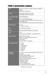
A7N8X-X specifications summary CPU Socket A for AMD Duron™/Athlon™/Athlon™ XP 3200+ or higher 400/333 MHz FSB Support Northbridge: NVIDIA® nForce2 400 Southbridge: NVIDIA® nForce2 MCP 400/333/266/200Mhz 3 x 184-pin DDR DIMM Sockets Max. 3 GB unbuffered PC3200/2700/2100/1600 non-ECC DDR RAM... memory. (Visit ASUS website for latest qualified DDR400 module list.) 5 x PCI 1 x AGP 8X (1.5V only) 2 x UltraDMA 133/100/66/33 Realtek ALC650 6CH ...
A7N8X-X specifications summary CPU Socket A for AMD Duron™/Athlon™/Athlon™ XP 3200+ or higher 400/333 MHz FSB Support Northbridge: NVIDIA® nForce2 400 Southbridge: NVIDIA® nForce2 MCP 400/333/266/200Mhz 3 x 184-pin DDR DIMM Sockets Max. 3 GB unbuffered PC3200/2700/2100/1600 non-ECC DDR RAM... memory. (Visit ASUS website for latest qualified DDR400 module list.) 5 x PCI 1 x AGP 8X (1.5V only) 2 x UltraDMA 133/100/66/33 Realtek ALC650 6CH ...
A7N8X-X User's Manual
Page 21
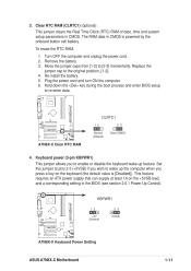
... 2 3 Clear CMOS A7N8X-X Normal (Default) A7N8X-X Clear RTC RAM 4. The RAM data in the BIOS (see section 2.5.1 Power Up Control). Clear RTC RAM (CLRTC1) (optional) This jumper clears the Real Time Clock (RTC) RAM of date, time and ...CMOS is [Disabled]). 3. Move the jumper caps from [1-2] to the original position, [1-2]. 4. To erase the RTC RAM: 1. Remove the battery. 3. Replace the jumper cap to [2-3] momentarily. Re-install the battery. 5. Hold down ... data. KBPWR1 1 2 +5V (Default) ® 2 3 +5VSB A7N8X-X A7N8X-X Keyboard Power Setting ASUS A7N8X-X Motherboard 1-11
... 2 3 Clear CMOS A7N8X-X Normal (Default) A7N8X-X Clear RTC RAM 4. The RAM data in the BIOS (see section 2.5.1 Power Up Control). Clear RTC RAM (CLRTC1) (optional) This jumper clears the Real Time Clock (RTC) RAM of date, time and ...CMOS is [Disabled]). 3. Move the jumper caps from [1-2] to the original position, [1-2]. 4. To erase the RTC RAM: 1. Remove the battery. 3. Replace the jumper cap to [2-3] momentarily. Re-install the battery. 5. Hold down ... data. KBPWR1 1 2 +5V (Default) ® 2 3 +5VSB A7N8X-X A7N8X-X Keyboard Power Setting ASUS A7N8X-X Motherboard 1-11


