
Motherboard DIY Troubleshooting Guide
Page 1
Motherboard A7N8X-X User Guide
Motherboard A7N8X-X User Guide

Motherboard DIY Troubleshooting Guide
Page 3
Features Contents Notices v Safety information vi ASUS contact information viii A7N8X-X specifications summary ix Chapter 1: Motherboard Info 1.1 Welcome 1-2 1.2 Package contents 1-2 1.3 Motherboard components 1-3 1.4 Motherboard layout 1-6 1.5 Before you proceed 1-7 1.6 Central Processing Unit (CPU 1-7 1.7 System memory 1-8 1.7.1 Installing a DIMM 1-8 1.8 Expansion slots 1-8 1.8.1 Configuring an expansion card 1-8 1.8.2 Standard Interrupt Assignments 1-9 1.8.3 AGP slot 1-9 1.9 Jumpers 1-10 1....
Features Contents Notices v Safety information vi ASUS contact information viii A7N8X-X specifications summary ix Chapter 1: Motherboard Info 1.1 Welcome 1-2 1.2 Package contents 1-2 1.3 Motherboard components 1-3 1.4 Motherboard layout 1-6 1.5 Before you proceed 1-7 1.6 Central Processing Unit (CPU 1-7 1.7 System memory 1-8 1.7.1 Installing a DIMM 1-8 1.8 Expansion slots 1-8 1.8.1 Configuring an expansion card 1-8 1.8.2 Standard Interrupt Assignments 1-9 1.8.3 AGP slot 1-9 1.9 Jumpers 1-10 1....
Motherboard DIY Troubleshooting Guide
Page 6
...not sure about the voltage of the electrical outlet you add a device. • Before connecting or removing signal cables from the motherboard, ensure that the power cables for the devices are unplugged before using an adpater or extension cord. Contact a qualified service technician ...that all power cables are unplugged. • Seek professional assistance before the signal cables are connected. vi Operation safety • Before installing the motherboard and adding devices on a stable surface. • If you detect any area where it may become wet. • Place the product on...
...not sure about the voltage of the electrical outlet you add a device. • Before connecting or removing signal cables from the motherboard, ensure that the power cables for the devices are unplugged before using an adpater or extension cord. Contact a qualified service technician ...that all power cables are unplugged. • Seek professional assistance before the signal cables are connected. vi Operation safety • Before installing the motherboard and adding devices on a stable surface. • If you detect any area where it may become wet. • Place the product on...
Motherboard DIY Troubleshooting Guide
Page 11
Motherboard Info ASUS A7N8X-X Motherboard 1-1 Chapter 1 This chapter gives information about the ASUS A7N8X-X motherboard that came with the system.This chapter includes the motherboard layout, jumper settings, and connector locations.
Motherboard Info ASUS A7N8X-X Motherboard 1-1 Chapter 1 This chapter gives information about the ASUS A7N8X-X motherboard that came with the system.This chapter includes the motherboard layout, jumper settings, and connector locations.
Motherboard DIY Troubleshooting Guide
Page 12
...your package with the list below. 1.2 Package contents Check your ASUS A7N8X-X package for the following items. ASUS A7N8X-X motherboard ATX form factor: 12 in x 9.6 in a motherboard. Unique ASUS features such as ASUS C.O.P., ASUS Q-Fan Technology and more are included to deliver the maximum ...upgrades or system reconfiguration, this chapter provides technical information about the motherboard. The ASUS A7N8X-X motherboard is loaded with the most advanced technologies to ensure the best user experience and value in ASUS A7N8X-X series support CD 40-pin 80-conductor ribbon cable ...
...your package with the list below. 1.2 Package contents Check your ASUS A7N8X-X package for the following items. ASUS A7N8X-X motherboard ATX form factor: 12 in x 9.6 in a motherboard. Unique ASUS features such as ASUS C.O.P., ASUS Q-Fan Technology and more are included to deliver the maximum ...upgrades or system reconfiguration, this chapter provides technical information about the motherboard. The ASUS A7N8X-X motherboard is loaded with the most advanced technologies to ensure the best user experience and value in ASUS A7N8X-X series support CD 40-pin 80-conductor ribbon cable ...
Motherboard DIY Troubleshooting Guide
Page 13
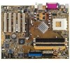
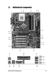
1.3 Motherboard components 12 3 45 18 17 16 15 14 13 19 20 28 27 26 ASUS A7N8X-X Motherboard 6 7 8 9 10 11 12 21 25 22 23 24 1-3
1.3 Motherboard components 12 3 45 18 17 16 15 14 13 19 20 28 27 26 ASUS A7N8X-X Motherboard 6 7 8 9 10 11 12 21 25 22 23 24 1-3
Motherboard DIY Troubleshooting Guide
Page 14
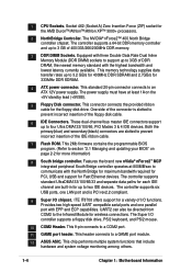
This standard 20-pin connector connects to a GAME port module. 12 ASUS ASIC. Both the primary(blue) and secondary(black) connectors are built-in for 333MHz DDR SDRAM. 4 ATX power connector. UART2 can also be directed from ... 400/333/266/200MHz DDR memory. 3 DDR DIMM Sockets. This chip performs multiple system functions that include hardware and system voltage monitoring among others. 1-4 Chapter 1: Motherboard Information The controller supports six USB ports, one parallel port with three Double Data Rate Dual Inline Memory Module (DDR DIMM) sockets to support up...
This standard 20-pin connector connects to a GAME port module. 12 ASUS ASIC. Both the primary(blue) and secondary(black) connectors are built-in for 333MHz DDR SDRAM. 4 ATX power connector. UART2 can also be directed from ... 400/333/266/200MHz DDR memory. 3 DDR DIMM Sockets. This chip performs multiple system functions that include hardware and system voltage monitoring among others. 1-4 Chapter 1: Motherboard Information The controller supports six USB ports, one parallel port with three Double Data Rate Dual Inline Memory Module (DDR DIMM) sockets to support up...
Motherboard DIY Troubleshooting Guide
Page 15
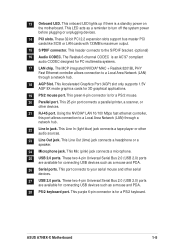
... RJ-45 port. This Accelerated Graphics Port (AGP) slot only supports 1.5V AGP 8X mode graphics cards for PC multimedia systems. 17 LAN chip. ASUS A7N8X-X Motherboard 1-5 This 25-pin port connects a parallel printer, a scanner, or other audio sources. 23 Line Out jack. This Mic (pink) jack connects... connection to your serial mouse and other serial devices. 27 USB 2.0 ports. The Realtek 6-channel CODEC is a standby power on the motherboard. 13 Onboard LED. This onboard LED lights up if there is an AC'97 compliant audio CODEC designed for 3D graphical applications. 19 ...
... RJ-45 port. This Accelerated Graphics Port (AGP) slot only supports 1.5V AGP 8X mode graphics cards for PC multimedia systems. 17 LAN chip. ASUS A7N8X-X Motherboard 1-5 This 25-pin port connects a parallel printer, a scanner, or other audio sources. 23 Line Out jack. This Mic (pink) jack connects... connection to your serial mouse and other serial devices. 27 USB 2.0 ports. The Realtek 6-channel CODEC is a standby power on the motherboard. 13 Onboard LED. This onboard LED lights up if there is an AC'97 compliant audio CODEC designed for 3D graphical applications. 19 ...
Motherboard DIY Troubleshooting Guide
Page 16
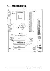
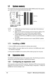
30.5cm (12.0in) 1.4 Motherboard layout PS/2 T: Mouse B: Keyboard USB3 USB4 COM1 24.5cm (9.64in) KBPWR1 USBPWR_34 Socket 462 CPU_FAN1 ATX Power Connector DDR DIMM1 (64/72 bit, 184-pin ...) PCI 1 PCI 2 ®A7N8X-X PCI 3 nForce2 MCP Chipset CR2032 3V Lithium Cell CMOS Power CLRTC1 2Mb BIOS Super I/O USB56 COM2 MODEM1 PWR_LED1 PCI 4 PCI 5 USBPWR_56 ASUS ASIC with Hardware Monitor GAME1 IR_CON1 IDELED1 PWRTMP1 CHASSIS1 CTRL_PANEL1 1-6 Chapter 1: Motherboard Information
30.5cm (12.0in) 1.4 Motherboard layout PS/2 T: Mouse B: Keyboard USB3 USB4 COM1 24.5cm (9.64in) KBPWR1 USBPWR_34 Socket 462 CPU_FAN1 ATX Power Connector DDR DIMM1 (64/72 bit, 184-pin ...) PCI 1 PCI 2 ®A7N8X-X PCI 3 nForce2 MCP Chipset CR2032 3V Lithium Cell CMOS Power CLRTC1 2Mb BIOS Super I/O USB56 COM2 MODEM1 PWR_LED1 PCI 4 PCI 5 USBPWR_56 ASUS ASIC with Hardware Monitor GAME1 IR_CON1 IDELED1 PWRTMP1 CHASSIS1 CTRL_PANEL1 1-6 Chapter 1: Motherboard Information
Motherboard DIY Troubleshooting Guide
Page 17
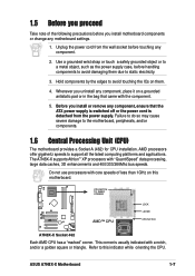
...case, before touching any component, ensure that came with core speeds of the following precautions before you install motherboard components or change any component, place it on them due to this motherboard. ® A7N8X-X CPU NOTCH TO INNER CORNER AMD™ CPU LOCK LEVER CPU NOTCH A7N8X-X ...Socket 462 Each AMD CPU has a "marked" corner. Unplug the power cord from the power supply. ASUS A7N8X-X Motherboard 1-7 Hold components by the edges to ...
...case, before touching any component, ensure that came with core speeds of the following precautions before you install motherboard components or change any component, place it on them due to this motherboard. ® A7N8X-X CPU NOTCH TO INNER CORNER AMD™ CPU LOCK LEVER CPU NOTCH A7N8X-X ...Socket 462 Each AMD CPU has a "marked" corner. Unplug the power cord from the power supply. ASUS A7N8X-X Motherboard 1-7 Hold components by the edges to ...
Motherboard DIY Troubleshooting Guide
Page 18
...a socket to avoid damaging the DIMM. 4. Generally, an IRQ must be exclusively assigned to one direction. 1.7 System memory The motherboard has three Double Data Rate (DDR) DIMM sockets that they support. 1.8.1 Configuring an expansion card Some expansion cards need an IRQ...asus.com) for latest DDR400 Qualified Vendor List. 1.7.1 Installing a DIMM 1. DIMMs with a notch so that it fits in only one function at a time. Make sure the memory frequency and bus frequency setting in the BIOS are already in the socket. 3. DO NOT force a DIMM into place. 1.8 Expansion slots The A7N8X-X motherboard...
...a socket to avoid damaging the DIMM. 4. Generally, an IRQ must be exclusively assigned to one direction. 1.7 System memory The motherboard has three Double Data Rate (DDR) DIMM sockets that they support. 1.8.1 Configuring an expansion card Some expansion cards need an IRQ...asus.com) for latest DDR400 Qualified Vendor List. 1.7.1 Installing a DIMM 1. DIMMs with a notch so that it fits in only one function at a time. Make sure the memory frequency and bus frequency setting in the BIOS are already in the socket. 3. DO NOT force a DIMM into place. 1.8 Expansion slots The A7N8X-X motherboard...
Motherboard DIY Troubleshooting Guide
Page 19
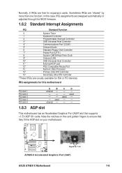
...Ultra ATA Controller 15* Secondary Ultra ATA Controller *These IRQs are usually available for 1.5v A7N8X-X Accelerated Graphics Port (AGP) ASUS A7N8X-X Motherboard 1-9 Note the notches on the card golden fingers to ensure that supports +1.5V AGP 8X cards. shared - - - 1.8.3 AGP slot This... motherboard has an Accelerated Graphics Port (AGP) slot that they fit the AGP slot on your motherboard. ® A7N8X-X Keyed for ISA or PCI devices. used - - Normally, 6 IRQs are "shared" ...
...Ultra ATA Controller 15* Secondary Ultra ATA Controller *These IRQs are usually available for 1.5v A7N8X-X Accelerated Graphics Port (AGP) ASUS A7N8X-X Motherboard 1-9 Note the notches on the card golden fingers to ensure that supports +1.5V AGP 8X cards. shared - - - 1.8.3 AGP slot This... motherboard has an Accelerated Graphics Port (AGP) slot that they fit the AGP slot on your motherboard. ® A7N8X-X Keyed for ISA or PCI devices. used - - Normally, 6 IRQs are "shared" ...
Motherboard DIY Troubleshooting Guide
Page 20
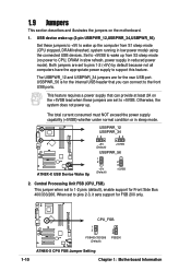
...) +5VSB USBPWR_56 1 2 +5V (Default) 2 3 +5VSB 2. This feature requires a power supply that you can provide at least 2A on the motherboard. 1. When set to 1-2 pins (default), enable support for the internal USB header that can connect to the front USB ports. Otherwise, the system does...FSB 200 only. ® A7N8X-X CPU_FSB 1 2 FSB400/333/266 (Default) 2 3 FSB200 1-10 A7N8X-X CPU FSB Jumper Setting Chapter 1: Motherboard Information 1.9 Jumpers This section describes and illustrates the jumpers on the +5VSB lead when these jumpers to +5V to wake up the computer from S3...
...) +5VSB USBPWR_56 1 2 +5V (Default) 2 3 +5VSB 2. This feature requires a power supply that you can provide at least 2A on the motherboard. 1. When set to 1-2 pins (default), enable support for the internal USB header that can connect to the front USB ports. Otherwise, the system does...FSB 200 only. ® A7N8X-X CPU_FSB 1 2 FSB400/333/266 (Default) 2 3 FSB200 1-10 A7N8X-X CPU FSB Jumper Setting Chapter 1: Motherboard Information 1.9 Jumpers This section describes and illustrates the jumpers on the +5VSB lead when these jumpers to +5V to wake up the computer from S3...

Motherboard DIY Troubleshooting Guide
Page 21
... lead, and a corresponding setting in the BIOS (see section 2.5.1 Power Up Control). ® A7N8X-X KBPWR1 12 +5V (Default) 23 +5VSB A7N8X-X Keyboard Power Setting ASUS A7N8X-X Motherboard 1-11 Re-install the battery. 5. The RAM data in CMOS. Clear RTC RAM (CLRTC1) (optional) This jumper clears the Real Time Clock (RTC) RAM of...
... lead, and a corresponding setting in the BIOS (see section 2.5.1 Power Up Control). ® A7N8X-X KBPWR1 12 +5V (Default) 23 +5VSB A7N8X-X Keyboard Power Setting ASUS A7N8X-X Motherboard 1-11 Re-install the battery. 5. The RAM data in CMOS. Clear RTC RAM (CLRTC1) (optional) This jumper clears the Real Time Clock (RTC) RAM of...
Motherboard DIY Troubleshooting Guide
Page 22
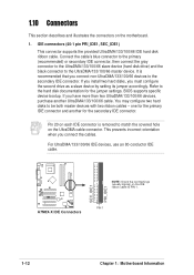
... configure two hard disks to the secondary IDE connector. one for the primary IDE connector and another UltraDMA/133/100/66 cable. PIN 1 1-12 Chapter 1: Motherboard Information If you install two hard disks, you connect the cables. Connect the cable's blue connector to the primary (recommended) or secondary IDE connector, then...-UltraDMA/133/100/66 devices to be both master devices with two ribbon cables - 1.10 Connectors This section describes and illustrates the connectors on the motherboard. 1.
... configure two hard disks to the secondary IDE connector. one for the primary IDE connector and another UltraDMA/133/100/66 cable. PIN 1 1-12 Chapter 1: Motherboard Information If you install two hard disks, you connect the cables. Connect the cable's blue connector to the primary (recommended) or secondary IDE connector, then...-UltraDMA/133/100/66 devices to be both master devices with two ribbon cables - 1.10 Connectors This section describes and illustrates the connectors on the motherboard. 1.
Motherboard DIY Troubleshooting Guide
Page 23
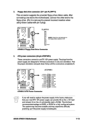
ATX power connectors (20-pin ATXPWR1) These connectors connect to PIN 1 PIN 1 A7N8X-X Floppy Disk Drive Connector 3. The minimum recommended wattage is inadequate. ASUS A7N8X-X Motherboard 1-13 2. FLOPPY1 ® A7N8X-X NOTE: Orient the red markings on the +5-volt standby lead (+5VSB). ATXPWR1 ® A7N8X-X +3.3VDC -12.... provided floppy drive ribbon cable. The plugs from the power supply are designed to fit these connectors in only one end to the motherboard, connect the other end to the floppy drive. (Pin 5 is removed to replace the power supply in the future, make sure...
ATX power connectors (20-pin ATXPWR1) These connectors connect to PIN 1 PIN 1 A7N8X-X Floppy Disk Drive Connector 3. The minimum recommended wattage is inadequate. ASUS A7N8X-X Motherboard 1-13 2. FLOPPY1 ® A7N8X-X NOTE: Orient the red markings on the +5-volt standby lead (+5VSB). ATXPWR1 ® A7N8X-X +3.3VDC -12.... provided floppy drive ribbon cable. The plugs from the power supply are designed to fit these connectors in only one end to the motherboard, connect the other end to the floppy drive. (Pin 5 is removed to replace the power supply in the future, make sure...
Motherboard DIY Troubleshooting Guide
Page 24
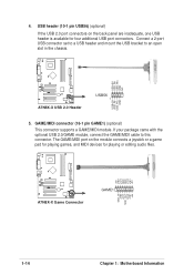
... audio files. +5V J1B2 J1CY GND GND J1CX J1B1 +5V ® A7N8X-X A7N8X-X Game Connector GAME1 MIDI_IN J2B2 J2CY MIDI_OUT J2CX J2B1 +5V 1-14 Chapter 1: Motherboard Information Connect a 2-port USB connector set to a USB header and mount the USB bracket to this connector. If your package came with the optional USB...
... audio files. +5V J1B2 J1CY GND GND J1CX J1B1 +5V ® A7N8X-X A7N8X-X Game Connector GAME1 MIDI_IN J2B2 J2CY MIDI_OUT J2CX J2B1 +5V 1-14 Chapter 1: Motherboard Information Connect a 2-port USB connector set to a USB header and mount the USB bracket to this connector. If your package came with the optional USB...
Motherboard DIY Troubleshooting Guide
Page 25
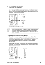
...The fan connectors support cooling fans of 350mA~740mA (8.88W max.) or a total of sufficient air flow within the system may damage the motherboard components. CPU_FAN1 Rotation +12V GND ® A7N8X-X CHA_FAN1 GND +12V Rotation A7N8X-X 12-Volt Cooling Fan Power Do not forget to connect... a chassis intrusion event. CHASSIS1 +5Volt (Power Supply Stand By) Chassis Signal Ground ® A7N8X-X 1 A7N8X-X Chassis Open Alarm Lead ASUS A7N8X-X Motherboard 1-15 By default, the pins labeled "Chassis Signal" and "Ground" are not jumpers! Connect the fan cables to the fan connectors. 6.
...The fan connectors support cooling fans of 350mA~740mA (8.88W max.) or a total of sufficient air flow within the system may damage the motherboard components. CPU_FAN1 Rotation +12V GND ® A7N8X-X CHA_FAN1 GND +12V Rotation A7N8X-X 12-Volt Cooling Fan Power Do not forget to connect... a chassis intrusion event. CHASSIS1 +5Volt (Power Supply Stand By) Chassis Signal Ground ® A7N8X-X 1 A7N8X-X Chassis Open Alarm Lead ASUS A7N8X-X Motherboard 1-15 By default, the pins labeled "Chassis Signal" and "Ground" are not jumpers! Connect the fan cables to the fan connectors. 6.
Motherboard DIY Troubleshooting Guide
Page 26
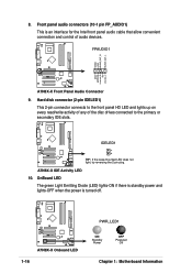
.... 8. Front panel audio connectors (10-1 pin FP_AUDIO1) This is turned off. ® A7N8X-X A7N8X-X Onboard LED 1-16 PWR_LED1 ON Standby Power OFF Powered Off Chapter 1: Motherboard Information A7N8X-X IDE Activity LED 10. Hard disk connector (2-pin IDELED1) This 2-pin connector connects to the primary or secondary IDE slots.
.... 8. Front panel audio connectors (10-1 pin FP_AUDIO1) This is turned off. ® A7N8X-X A7N8X-X Onboard LED 1-16 PWR_LED1 ON Standby Power OFF Powered Off Chapter 1: Motherboard Information A7N8X-X IDE Activity LED 10. Hard disk connector (2-pin IDELED1) This 2-pin connector connects to the primary or secondary IDE slots.

Motherboard DIY Troubleshooting Guide
Page 27
... to this connector then install the bracket into a slot opening at the back of the system chassis. ® A7N8X-X COM2 PIN 1 A7N8X-X Serial COM2 Bracket ASUS A7N8X-X Motherboard 1-17 MODEM1 CD1 (Black) AUX1 (White) ® A7N8X-X A7N8X-X Internal Audio Connectors 12. Connect the bracket cable to receive stereo audio input from sound...
... to this connector then install the bracket into a slot opening at the back of the system chassis. ® A7N8X-X COM2 PIN 1 A7N8X-X Serial COM2 Bracket ASUS A7N8X-X Motherboard 1-17 MODEM1 CD1 (Black) AUX1 (White) ® A7N8X-X A7N8X-X Internal Audio Connectors 12. Connect the bracket cable to receive stereo audio input from sound...


