User Guide
Page 3
... more information x Conventions used in this guide xi Typography xi Z9NA-D6 series specifications summary xii Chapter 1: Product introduction 1.1 Welcome 1-3 1.2 Package contents 1-3 1.3 Serial number label 1-4 1.4 Special features 1-4 1.4.1 Product highlights 1-4 1.4.2 Innovative ASUS features 1-6 Chapter 2: Hardware information 2.1 Before you proceed 2-3 2.2 Motherboard overview 2-4 2.2.1 Placement direction 2-4 2.2.2 Screw holes 2-4 2.2.3 Motherboard layout 2-5 2.2.4 Layout contents 2-7 2.3 Central Processing Unit (CPU 2-9 2.3.1 Installing the...
... more information x Conventions used in this guide xi Typography xi Z9NA-D6 series specifications summary xii Chapter 1: Product introduction 1.1 Welcome 1-3 1.2 Package contents 1-3 1.3 Serial number label 1-4 1.4 Special features 1-4 1.4.1 Product highlights 1-4 1.4.2 Innovative ASUS features 1-6 Chapter 2: Hardware information 2.1 Before you proceed 2-3 2.2 Motherboard overview 2-4 2.2.1 Placement direction 2-4 2.2.2 Screw holes 2-4 2.2.3 Motherboard layout 2-5 2.2.4 Layout contents 2-7 2.3 Central Processing Unit (CPU 2-9 2.3.1 Installing the...
User Guide
Page 9
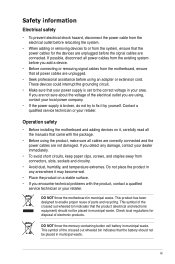
... possible, disconnect all power cables from the existing system before you are using, contact your area. Operation safety • Before installing the motherboard and adding devices on a stable surface. • If you detect any area where it may become wet. • Place the product...a qualified service technician or your dealer immediately. • To avoid short circuits, keep paper clips, screws, and staples away from the motherboard, ensure that all power cables are unplugged. • Seek professional assistance before the signal cables are not damaged. This product has been ...
... possible, disconnect all power cables from the existing system before you are using, contact your area. Operation safety • Before installing the motherboard and adding devices on a stable surface. • If you detect any area where it may become wet. • Place the product...a qualified service technician or your dealer immediately. • To avoid short circuits, keep paper clips, screws, and staples away from the motherboard, ensure that all power cables are unplugged. • Seek professional assistance before the signal cables are not damaged. This product has been ...
User Guide
Page 10
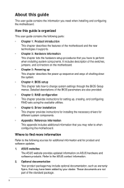
...Chapter 2: Hardware information This chapter lists the hardware setup procedures that may have to when configuring the motherboard. ASUS websites The ASUS website provides updated information on the motherboard. • Chapter 3: Powering up This chapter describes the power up , creating, and configuring ... components. • Appendix: Reference information This appendix includes additional information that you need when installing and configuring the motherboard. Refer to change system settings through the BIOS Setup menus. It includes description of shutting down the system. &#...
...Chapter 2: Hardware information This chapter lists the hardware setup procedures that may have to when configuring the motherboard. ASUS websites The ASUS website provides updated information on the motherboard. • Chapter 3: Powering up This chapter describes the power up , creating, and configuring ... components. • Appendix: Reference information This appendix includes additional information that you need when installing and configuring the motherboard. Refer to change system settings through the BIOS Setup menus. It includes description of shutting down the system. &#...

User Guide
Page 15
This chapter describes the motherboard introPdruoc1dtuiocnt features and the new technologies it supports.
This chapter describes the motherboard introPdruoc1dtuiocnt features and the new technologies it supports.
User Guide
Page 17
... following items. Z9NA-D6 Series Cables Accessories SATA 6G cable SATA 3G cable SATA DOM USB power cable IO shield Standard Gift Box Pack 2 8 (Z9NA-D6) 4 (Z9NA-D6C) 1 1 Standard Bulk Pack --- -1 Support CD 1 1 Application CD ASWM Enterprise SDVD 1 1 Documentation User Guide Packing Qty. 1 1pc per carton 1 10pcs per carton If any of ASUS quality motherboards! 1.1 Welcome...
... following items. Z9NA-D6 Series Cables Accessories SATA 6G cable SATA 3G cable SATA DOM USB power cable IO shield Standard Gift Box Pack 2 8 (Z9NA-D6) 4 (Z9NA-D6C) 1 1 Standard Bulk Pack --- -1 Support CD 1 1 Application CD ASWM Enterprise SDVD 1 1 Documentation User Guide Packing Qty. 1 1pc per carton 1 10pcs per carton If any of ASUS quality motherboards! 1.1 Welcome...
User Guide
Page 18
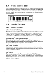
...of up to 8.0GT/s. The Intel® EM64T feature allows your problems. Z9NA-D6 xxS2xxxxxxxx Made in China 合格 1.4 Special features 1.4.1 Product highlights Latest Processor Technology The motherboard supports the latest Intel Xeon® processor E5-2400 product family in LGA ... and automatically allows it is operating below . 1.3 Serial number label Before requesting support from the ASUS Technical Support team, you must take note of the motherboard's serial number containing 12 characters xxS2xxxxxxxx shown as the figure below power, temperature, and current limits...
...of up to 8.0GT/s. The Intel® EM64T feature allows your problems. Z9NA-D6 xxS2xxxxxxxx Made in China 合格 1.4 Special features 1.4.1 Product highlights Latest Processor Technology The motherboard supports the latest Intel Xeon® processor E5-2400 product family in LGA ... and automatically allows it is operating below . 1.3 Serial number label Before requesting support from the ASUS Technical Support team, you must take note of the motherboard's serial number containing 12 characters xxS2xxxxxxxx shown as the figure below power, temperature, and current limits...
User Guide
Page 19
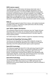
... to 6Gb/s data transfer rates. Serial ATA allows thinner, more flexible cables with peak bandwidth of PCIe 2.0. Also, the motherboard can support LRDIMM (Load reduced DIMM) which helps reduce CPU usage, thus increasing throughput to achieve highlyreliable network connections, outstanding performance...that features data transfer rates of 1600/1333/1066 MHz to meet the higher bandwidth requirements of current bus systems. ASUS Z9NA-D6 1-5 PCIe 3.0 The motherboard supports the latest PCIe 3.0 device, which makes it an ideal memory solution. The 3-channel DDR3 architecture boosts system...
... to 6Gb/s data transfer rates. Serial ATA allows thinner, more flexible cables with peak bandwidth of PCIe 2.0. Also, the motherboard can support LRDIMM (Load reduced DIMM) which helps reduce CPU usage, thus increasing throughput to achieve highlyreliable network connections, outstanding performance...that features data transfer rates of 1600/1333/1066 MHz to meet the higher bandwidth requirements of current bus systems. ASUS Z9NA-D6 1-5 PCIe 3.0 The motherboard supports the latest PCIe 3.0 device, which makes it an ideal memory solution. The 3-channel DDR3 architecture boosts system...

User Guide
Page 20
... voltage monitoring The CPU temperature is monitored for timely failure detection. PIKE (Proprietary I /O solutions. USB 2.0 technology The motherboard implements the Universal Serial Bus (USB) 2.0 specification, dramatically increasing the connection speed from the 12 Mbps bandwidth on USB ...the voltage levels to ensure stable supply of validation efforts and hardware cost for critical components. 1.4.2 Innovative ASUS features ASUS Fan Speed control technology The ASUS Fan Speed control technology smartly adjusts the fan speeds according to the system loading to different destinations. ...
... voltage monitoring The CPU temperature is monitored for timely failure detection. PIKE (Proprietary I /O solutions. USB 2.0 technology The motherboard implements the Universal Serial Bus (USB) 2.0 specification, dramatically increasing the connection speed from the 12 Mbps bandwidth on USB ...the voltage levels to ensure stable supply of validation efforts and hardware cost for critical components. 1.4.2 Innovative ASUS features ASUS Fan Speed control technology The ASUS Fan Speed control technology smartly adjusts the fan speeds according to the system loading to different destinations. ...
User Guide
Page 21
It includes description of the jumpers and connectors on the motherboard. This chapter lists the hardware setup procedures that you have to perform when installing system components. Chapter 2: 2 Hardware information
It includes description of the jumpers and connectors on the motherboard. This chapter lists the hardware setup procedures that you have to perform when installing system components. Chapter 2: 2 Hardware information
User Guide
Page 22
Chapter summary 2 2.1 Before you proceed 2-3 2.2 Motherboard overview 2-4 2.3 Central Processing Unit (CPU 2-9 2.4 System memory 2-13 2.5 Expansion slots 2-16 2.6 Onboard LEDs 2-20 2.7 Jumpers 2-22 2.8 Connectors 2-26 ASUS Z9NA-D6
Chapter summary 2 2.1 Before you proceed 2-3 2.2 Motherboard overview 2-4 2.3 Central Processing Unit (CPU 2-9 2.4 System memory 2-13 2.5 Expansion slots 2-16 2.6 Onboard LEDs 2-20 2.7 Jumpers 2-22 2.8 Connectors 2-26 ASUS Z9NA-D6
User Guide
Page 23
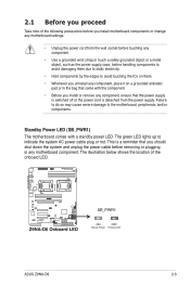
... before removing or plugging in the bag that came with a standby power LED. ASUS Z9NA-D6 2-3 Failure to do so may cause severe damage to indicate the system AC power cable plug or not. Standby Power LED (SB_PWR1) The motherboard comes with the component. • Before you install or remove any component, ensure...
... before removing or plugging in the bag that came with a standby power LED. ASUS Z9NA-D6 2-3 Failure to do so may cause severe damage to indicate the system AC power cable plug or not. Standby Power LED (SB_PWR1) The motherboard comes with the component. • Before you install or remove any component, ensure...
User Guide
Page 24
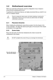
Doing so can cause you physical injury and damage motherboard components! 2.2.1 Placement direction When installing the motherboard, ensure that you install it in the correct orientation. Failure to do so can damage the motherboard. To optimize the motherboard features, we highly recommend that you place it . Ensure to ...unplug the chassis power cord before installing or removing the motherboard. The edge with external ports goes to the rear part of the chassis 2-4 Chapter 2: Hardware information DO NOT overtighten the...
Doing so can cause you physical injury and damage motherboard components! 2.2.1 Placement direction When installing the motherboard, ensure that you install it in the correct orientation. Failure to do so can damage the motherboard. To optimize the motherboard features, we highly recommend that you place it . Ensure to ...unplug the chassis power cord before installing or removing the motherboard. The edge with external ports goes to the rear part of the chassis 2-4 Chapter 2: Hardware information DO NOT overtighten the...
User Guide
Page 29
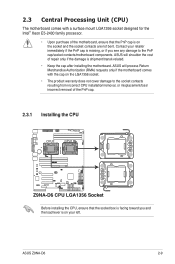
...shoulder the cost of repair only if the damage is on the socket and the socket contacts are not bent. ASUS Z9NA-D6 2-9 2.3 Central Processing Unit (CPU) The motherboard comes with the cap on the LGA1356 socket. • The product warranty does not cover damage to the ...the CPU, ensure that the PnP cap is shipment/transit-related. • Keep the cap after installing the motherboard. ASUS will process Return Merchandise Authorization (RMA) requests only if the motherboard comes with a surface mount LGA1356 socket designed for the Intel® Xeon E5-2400 family processor. •...
...shoulder the cost of repair only if the damage is on the socket and the socket contacts are not bent. ASUS Z9NA-D6 2-9 2.3 Central Processing Unit (CPU) The motherboard comes with the cap on the LGA1356 socket. • The product warranty does not cover damage to the ...the CPU, ensure that the PnP cap is shipment/transit-related. • Keep the cap after installing the motherboard. ASUS will process Return Merchandise Authorization (RMA) requests only if the motherboard comes with a surface mount LGA1356 socket designed for the Intel® Xeon E5-2400 family processor. •...

User Guide
Page 30
2.3.2 Intel LGA1356 Socket 1. Retention tab A B Load lever Load plate D C 4. To prevent damage to a 100º angle (D). Locate the CPU socket on the motherboard. 2. Lift the load lever in the direction of the arrow to a 135º angle (C), then lift the load plate with your thumb and forefinger to ...
2.3.2 Intel LGA1356 Socket 1. Retention tab A B Load lever Load plate D C 4. To prevent damage to a 100º angle (D). Locate the CPU socket on the motherboard. 2. Lift the load lever in the direction of the arrow to a 135º angle (C), then lift the load plate with your thumb and forefinger to ...
User Guide
Page 32
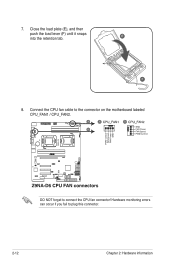
E F 8. Hardware monitoring errors can occur if you fail to the connector on the motherboard labeled CPU_FAN1 / CPU_FAN2. 7. Connect the CPU fan cable to plug this connector. 2-12 Chapter 2: Hardware information Close the load plate (E), and then push the load lever (F) until it snaps into the retention tab. DO NOT forget to connect the CPU fan connector!
E F 8. Hardware monitoring errors can occur if you fail to the connector on the motherboard labeled CPU_FAN1 / CPU_FAN2. 7. Connect the CPU fan cable to plug this connector. 2-12 Chapter 2: Hardware information Close the load plate (E), and then push the load lever (F) until it snaps into the retention tab. DO NOT forget to connect the CPU fan connector!
User Guide
Page 33
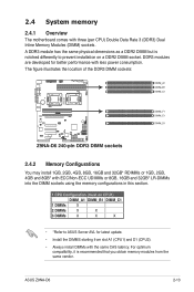
...DIMM sockets using the memory configurations in this section. 1 CPU Configuration (must on a DDR2 DIMM socket. ASUS Z9NA-D6 2-13 2.4 System memory 2.4.1 Overview The motherboard comes with the same CAS latency. A DDR3 module has the same physical dimensions as a DDR2 DIMM but ... notched differently to prevent installation on CPU1) DIMM_A1 DIMM_B1 DIMM_C1 1 DIMMs X 2 DIMMs X X 3 DIMMs X X X • *Refer to ASUS Server AVL for better performance with less power consumption. DDR3 modules are developed for latest update. • Install the DIMMS starting from the same vendor...
...DIMM sockets using the memory configurations in this section. 1 CPU Configuration (must on a DDR2 DIMM socket. ASUS Z9NA-D6 2-13 2.4 System memory 2.4.1 Overview The motherboard comes with the same CAS latency. A DDR3 module has the same physical dimensions as a DDR2 DIMM but ... notched differently to prevent installation on CPU1) DIMM_A1 DIMM_B1 DIMM_C1 1 DIMMs X 2 DIMMs X X 3 DIMMs X X X • *Refer to ASUS Server AVL for better performance with less power consumption. DDR3 modules are developed for latest update. • Install the DIMMS starting from the same vendor...
User Guide
Page 35
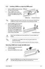
... to the user guide for qualified vendor lists of the DIMM. 3 Locked Retaining Clip Always insert the DIMM into a socket in the motherboard package. • Refer to unlock the DIMM. 2. ASUS Z9NA-D6 2-15 Remove the DIMM from a single clip DIMM socket 1. DIMM slot key 1 Unlocked retaining clip A DIMM is keyed with a notch...
... to the user guide for qualified vendor lists of the DIMM. 3 Locked Retaining Clip Always insert the DIMM into a socket in the motherboard package. • Refer to unlock the DIMM. 2. ASUS Z9NA-D6 2-15 Remove the DIMM from a single clip DIMM socket 1. DIMM slot key 1 Unlocked retaining clip A DIMM is keyed with a notch...
User Guide
Page 36
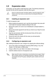
...may cause you intend to install expansion cards. The following subsections describe the slots and the expansion cards that you physical injury and damage motherboard components. 2.5.1 Installing an expansion card To install an expansion card: 1. Secure the card to the chassis with the slot and press... firmly until the card is already installed in a chassis). 3. Remove the system unit cover (if your motherboard is completely seated on the slot. 5. Ensure to the card. 2.5 Expansion slots In the future, you removed earlier. 6. Refer to do...
...may cause you intend to install expansion cards. The following subsections describe the slots and the expansion cards that you physical injury and damage motherboard components. 2.5.1 Installing an expansion card To install an expansion card: 1. Secure the card to the chassis with the slot and press... firmly until the card is already installed in a chassis). 3. Remove the system unit cover (if your motherboard is completely seated on the slot. 5. Ensure to the card. 2.5 Expansion slots In the future, you removed earlier. 6. Refer to do...
User Guide
Page 38
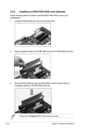
Align the golden fingers of the PIKE RAID card with the PIKE RAID card slot. 3. Ensure that it is completely seated on the motherboard. 2. Please refer to install an optional ASUS PIKE RAID card on your motherboard. 1. Locate the PIKE RAID card slot on the PIKE RAID card slot. 2.5.8 Installing an ASUS PIKE RAID card (Optional) Follow the steps below to Chapter 2.8.2 for SAS connector location. 2-18 Chapter 2: Hardware information Insert the PIKE RAID card into the PIKE RAID card slot.
Align the golden fingers of the PIKE RAID card with the PIKE RAID card slot. 3. Ensure that it is completely seated on the motherboard. 2. Please refer to install an optional ASUS PIKE RAID card on your motherboard. 1. Locate the PIKE RAID card slot on the PIKE RAID card slot. 2.5.8 Installing an ASUS PIKE RAID card (Optional) Follow the steps below to Chapter 2.8.2 for SAS connector location. 2-18 Chapter 2: Hardware information Insert the PIKE RAID card into the PIKE RAID card slot.
User Guide
Page 39
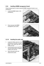
2.5.9 Installing ASMB6 management board Follow the steps below to the chassis with the PCIE5 card slot. 2. Ensure that it is completely seated on the motherboard. 2. Secure the audio card to install an optional ASMB6 management board on the motherboard and align the golden fingers of the audio card with a screw. Insert the audio card into the PCIE5 card slot. Locate the ASMB6 header on the card slot. 3. Locate the PCIE5 card slot on your motherboard. 1. ASUS Z9NA-D6 2-19 Orient and press the ASMB6 management card in place. 2.5.10 Installing the audio card 1.
2.5.9 Installing ASMB6 management board Follow the steps below to the chassis with the PCIE5 card slot. 2. Ensure that it is completely seated on the motherboard. 2. Secure the audio card to install an optional ASMB6 management board on the motherboard and align the golden fingers of the audio card with a screw. Insert the audio card into the PCIE5 card slot. Locate the ASMB6 header on the card slot. 3. Locate the PCIE5 card slot on your motherboard. 1. ASUS Z9NA-D6 2-19 Orient and press the ASMB6 management card in place. 2.5.10 Installing the audio card 1.

